Transcription
Model GC-TBZ48Battery Powered Z-WaveThermostatInstallation & Operation GuideMODEFANOffAuto74F
Table of ContentsTypical Wiring for Standard Gas/Electric HVAC System . . . . . . . . . . . . . . . . . . . . . . . . . . . . . . . . . . . . . .2Typical Wiring for Heat Pump HVAC System . . . . . . . . . . . . . . . . . . . . . . . . . . . . . . . . . . . . . . . . . . . . . . .3Thermostat Power . . . . . . . . . . . . . . . . . . . . . . . . . . . . . . . . . . . . . . . . . . . . . . . . . . . . . . . . . . . . . . . . . . . .4The C Wire. . . . . . . . . . . . . . . . . . . . . . . . . . . . . . . . . . . . . . . . . . . . . . . . . . . . . . . . . . . . . . . . . . . . . .424VAC Power . . . . . . . . . . . . . . . . . . . . . . . . . . . . . . . . . . . . . . . . . . . . . . . . . . . . . . . . . . . . . . . . . . .4Ba ery Power . . . . . . . . . . . . . . . . . . . . . . . . . . . . . . . . . . . . . . . . . . . . . . . . . . . . . . . . . . . . . . . . . . .4Z-Wave Opera on when Ba ery Powered . . . . . . . . . . . . . . . . . . . . . . . . . . . . . . . . . . . . . . . . . . . .4Remove Exis ng Thermostat . . . . . . . . . . . . . . . . . . . . . . . . . . . . . . . . . . . . . . . . . . . . . . . . . . . . . . . . . . .5Wiring Colors . . . . . . . . . . . . . . . . . . . . . . . . . . . . . . . . . . . . . . . . . . . . . . . . . . . . . . . . . . . . . . . . . . .5Install the Back Panel . . . . . . . . . . . . . . . . . . . . . . . . . . . . . . . . . . . . . . . . . . . . . . . . . . . . . . . . . . . . . . . . . .6Standard HVAC System Connec ons . . . . . . . . . . . . . . . . . . . . . . . . . . . . . . . . . . . . . . . . . . . . . . . . . . . . .7Single and Dual Transformer Systems (Split Systems) . . . . . . . . . . . . . . . . . . . . . . . . . . . . . . . . . . .7Single Transformer System . . . . . . . . . . . . . . . . . . . . . . . . . . . . . . . . . . . . . . . . . . . . . . . . . . . .7Dual Transformer Systems . . . . . . . . . . . . . . . . . . . . . . . . . . . . . . . . . . . . . . . . . . . . . . . . . . . .8Heat Pump HVAC System Connec ons . . . . . . . . . . . . . . . . . . . . . . . . . . . . . . . . . . . . . . . . . . . . . . . . . . .9Mount the Thermostat . . . . . . . . . . . . . . . . . . . . . . . . . . . . . . . . . . . . . . . . . . . . . . . . . . . . . . . . . . . . . . .10Ba ery Installa on. . . . . . . . . . . . . . . . . . . . . . . . . . . . . . . . . . . . . . . . . . . . . . . . . . . . . . . . . . . . . . . . . . .10Thermostat Setup Menus . . . . . . . . . . . . . . . . . . . . . . . . . . . . . . . . . . . . . . . . . . . . . . . . . . . . . . . . . . . . .11Preset HVAC System se ngs . . . . . . . . . . . . . . . . . . . . . . . . . . . . . . . . . . . . . . . . . . . . . . . . . . . . . .11Wait Mode . . . . . . . . . . . . . . . . . . . . . . . . . . . . . . . . . . . . . . . . . . . . . . . . . . . . . . . . . . . . . . . . . . . .11Minimum Run Time (MRT) . . . . . . . . . . . . . . . . . . . . . . . . . . . . . . . . . . . . . . . . . . . . . . . . . . . . . . .11Entering Menu Mode . . . . . . . . . . . . . . . . . . . . . . . . . . . . . . . . . . . . . . . . . . . . . . . . . . . . . . . . . . .12Menu Mode Naviga on . . . . . . . . . . . . . . . . . . . . . . . . . . . . . . . . . . . . . . . . . . . . . . . . . . . . .12System Menu . . . . . . . . . . . . . . . . . . . . . . . . . . . . . . . . . . . . . . . . . . . . . . . . . . . . . . . . . . . . . . . . . .13System Type . . . . . . . . . . . . . . . . . . . . . . . . . . . . . . . . . . . . . . . . . . . . . . . . . . . . . . . . . . . . . . .13Fan Type (For Standard HVAC systems only) . . . . . . . . . . . . . . . . . . . . . . . . . . . . . . . . . . . .13Changeover Type (For Heat Pump HVAC Systems Only) . . . . . . . . . . . . . . . . . . . . . . . . . . .13Z-Wave Installa on . . . . . . . . . . . . . . . . . . . . . . . . . . . . . . . . . . . . . . . . . . . . . . . . . . . . . . . . . . . . . .14Inclusion and Exclusion . . . . . . . . . . . . . . . . . . . . . . . . . . . . . . . . . . . . . . . . . . . . . . . . . . . . . . . . . .14Clock Menu . . . . . . . . . . . . . . . . . . . . . . . . . . . . . . . . . . . . . . . . . . . . . . . . . . . . . . . . . . . . . . . . . . . .15Se ng the Clock . . . . . . . . . . . . . . . . . . . . . . . . . . . . . . . . . . . . . . . . . . . . . . . . . . . . . . . . . . .15INFO Menu . . . . . . . . . . . . . . . . . . . . . . . . . . . . . . . . . . . . . . . . . . . . . . . . . . . . . . . . . . . . . . . . . . . .15Advanced System Se ngs Menu . . . . . . . . . . . . . . . . . . . . . . . . . . . . . . . . . . . . . . . . . . . . . . . . . .16Thermostat Opera on . . . . . . . . . . . . . . . . . . . . . . . . . . . . . . . . . . . . . . . . . . . . . . . . . . . . . . . . . . . . . . . .18Main Thermostat Screen . . . . . . . . . . . . . . . . . . . . . . . . . . . . . . . . . . . . . . . . . . . . . . . . . . . . . . . . .18Backlight and Bu on Opera on . . . . . . . . . . . . . . . . . . . . . . . . . . . . . . . . . . . . . . . . . . . . . . . . . . .18Display . . . . . . . . . . . . . . . . . . . . . . . . . . . . . . . . . . . . . . . . . . . . . . . . . . . . . . . . . . . . . . . . . . . . . . . .18Staging Indicators . . . . . . . . . . . . . . . . . . . . . . . . . . . . . . . . . . . . . . . . . . . . . . . . . . . . . . . . . . . . . . .18Se ng the System Mode . . . . . . . . . . . . . . . . . . . . . . . . . . . . . . . . . . . . . . . . . . . . . . . . . . . . . . . . .19System Modes . . . . . . . . . . . . . . . . . . . . . . . . . . . . . . . . . . . . . . . . . . . . . . . . . . . . . . . . . . . . .19Special Heat Pump Mode: Emergency Heat . . . . . . . . . . . . . . . . . . . . . . . . . . . . . . . . . . . . .19Se ng the Hea ng or Cooling Temperature Setpoint. . . . . . . . . . . . . . . . . . . . . . . . . . . . . . . . . .20Automa c Setpoint Push . . . . . . . . . . . . . . . . . . . . . . . . . . . . . . . . . . . . . . . . . . . . . . . . . . . .20Se ng the Fan Mode . . . . . . . . . . . . . . . . . . . . . . . . . . . . . . . . . . . . . . . . . . . . . . . . . . . . . . . . . . . .21Fan Modes . . . . . . . . . . . . . . . . . . . . . . . . . . . . . . . . . . . . . . . . . . . . . . . . . . . . . . . . . . . . . . . .21User Customiza on . . . . . . . . . . . . . . . . . . . . . . . . . . . . . . . . . . . . . . . . . . . . . . . . . . . . . . . . . . . . .22User preference se ngs. . . . . . . . . . . . . . . . . . . . . . . . . . . . . . . . . . . . . . . . . . . . . . . . . . . . .22Clock Menu . . . . . . . . . . . . . . . . . . . . . . . . . . . . . . . . . . . . . . . . . . . . . . . . . . . . . . . . . . . . . . . . . . . .23Se ng the Clock . . . . . . . . . . . . . . . . . . . . . . . . . . . . . . . . . . . . . . . . . . . . . . . . . . . . . . . . . . .23INFO Menu . . . . . . . . . . . . . . . . . . . . . . . . . . . . . . . . . . . . . . . . . . . . . . . . . . . . . . . . . . . . . . . . . . . .23Specifica ons . . . . . . . . . . . . . . . . . . . . . . . . . . . . . . . . . . . . . . . . . . . . . . . . . . . . . . . . . . . . . . . . . . . . . . .24Regulatory Informa on . . . . . . . . . . . . . . . . . . . . . . . . . . . . . . . . . . . . . . . . . . . . . . . . . . . . . . . . . . . . . . .25Industry Canada No ces . . . . . . . . . . . . . . . . . . . . . . . . . . . . . . . . . . . . . . . . . . . . . . . . . . . . . . . . . . . . . .25Limited Warranty . . . . . . . . . . . . . . . . . . . . . . . . . . . . . . . . . . . . . . . . . . . . . . . . . . . . . . . . . . . . . . . . . . . .25
GC-TBZ48BATTERY POWERED Z-WAVE THERMOSTATINSTALLATION INSTRUCTIONSThe Z-Wave Thermostat (GC-TBZ48) is a programmable, Z-Wave communica ng thermostat.It can be powered using 24VAC (if both “R”&”C”wires are available at the thermostat), orusing four (4) AA ba eries. Using Z-Wave technology, end users have the ability to use the2GIG Go!Control panel to control the thermostat, configure programming se ngs, as wellas to display current condi ons in the home or office.Figure 1. Z-Wave Thermostat Front ViewGC-TBZ48 THERMOSTATMODEFANANCHORS (2)YBATTERIES (4) PHILLIPS ADHESIVE WIRING LABELS SHEETSCREWS (2)Features Include: A fixed format display with white backlight Hea ng and cooling setup display op ons System mode (OFF, Heat, Cool, Auto,E-Heat) Fan mode control and display (Auto, ON) Changeover type for Heat Pump (HP)systemsCompatible with 24 VAC gas, oil, orelectric heating and air conditioningsystems; or gas millivolt heatingsystemsDO NOT USE ON 120VAC SYSTEMS!Standard Systems 1 Stage Hea ng and Cooling 2 Stage Hea ng and Cooling On-screen setup of HVAC type, Fan typeHeat Pump Systems 1 Stage Hea ng and Cooling F/C mode, and sensor calibra on 2 Stage Hea ng and CoolingBox Contents 1 Z-Wave Thermostat 2nd or 3rd Stage Aux Hea ng (Electric HeatStripsInstallation Outline Step 1 Remove Exis ng Thermostat 1 Sheet Adhesive Wiring Labels Step 2 Install GC-TBZ48 Thermostat 2 Plas c Wall Anchors Step 3 Setup Thermostat to match SystemType 4 AA Ba eries Step 4 Install into Z-Wave NetworkCopyright 2015 Nortek Security & Control LLC1
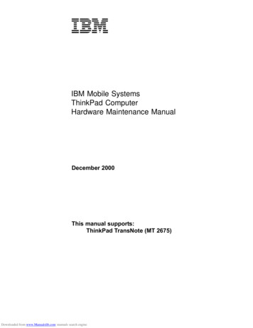
Typical Wiring for Standard Gas/Electric HVAC SystemSTANDARD HVAC SYSTEMTYPICAL THERMOSTAT WIRING COLORS.CAUTION: VERIFY THAT ORIGINAL WIRINGMATCHES. COLORS MAY BE DIFFERENTTHERMOSTAT C 24VAC COMMONR 24VAC RETURNW1 HEAT STAGE 1W2 HEAT STAGE 2G FANY1 COMPRESSOR STAGE 1Y2 COMPRESSOR STAGE 2C WIRE IS NOT REQUIREDFOR BATTERY OPERATIONC WIRE IS REQUIRED FOR24VAC OPERATIONY2 Y1 G RC C RH W1 W2FOR SINGLETRANSFORMER SYSTEMSCONNECT R WIRE TOEITHER RC OR RHTERMINALINTERNAL RC RH JUMPERTHERMOSTAT BACK PANELDEFAULT THERMOSTAT SETUP:TYPE: STANDARD HVACFAN: GAS HEAT1 STAGE HEATING1 STAGE COOLINGNO SETUP CHANGE REQUIREDFOR THIS CONFIGURATION2 Copyright 2015 Nortek Security & ControlFOR SYSTEMS WITH SEPARATEHEATING AND COOLINGTRANSFORMERS, CONNECTHEATING R TO RH AND COOLINGR TO RC. NOTE! THE RC-RHJUMPER MUST BE CUTON THE THERMOSTAT BOARD.
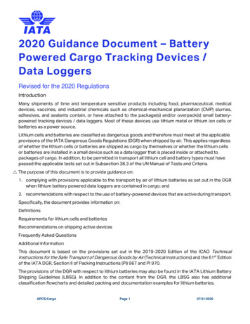
Typical Wiring for Heat Pump HVAC SystemTYPICAL THERMOSTAT WIRING COLORS.CAUTION: VERIFY THAT ORIGINAL WIRINGMATCHES. COLORS MAY BE DIFFERENTHEAT PUMP HVAC SYSTEMTHERMOSTAT C 24VAC COMMONR 24VAC RETURNW1 HEAT STAGE 1O CHANGEOVER VALVEG FANY1 COMPRESSOR STAGE 1Y2 COMPRESSOR STAGE 2O or B WIREC WIRE IS NOT REQUIREDFOR BATTERY OPERATIONNOTE! MOST HEAT PUMPSYSTEMS DO HAVE THE CWIRE AND THETHERMOSTAT CAN BEPOWERED BY THE 24VACFROM THE HVAC SYSTEMCONNECT THE R WIRE TOEITHER R TERMINAL.Y2 Y1 G R C R W1 OBATTERIES ARE NOTREQUIRED FOR 24VACPOWERED SYSTEMSINTERNAL R R JUMPERR R ARE JUMPEREDTOGETHER INTERNALLYTHERMOSTAT BACK PANELNOTE: IF HEATING IS OCCURINGWHEN COOOLING IS EXPECTED,OR VICE-VERSA, CHANGE THECHANGEOVER TYPE TO THEOPPOSITE SETTING.Copyright 2015 Nortek Security & Control LLC3
Thermostat PowerThe thermostat can be powered by either 24VAC from the HVAC system or from four (4) type AAinternal ba eries. DO NOT use this thermostat for line voltage controls (120/240VAC).The C WireIf the 24VAC common wire (usually blue) is present and is connected to 24VAC common at the HVACsystem end, the thermostat can be powered from the HVAC system and ba eries are not required. Ifthere is no common wire, ba eries are required.24VAC PowerPowering the thermostat with 24VAC power requires both the 24VAC “C” common wire (typically ablue wire) and the 24VAC ”R” return wire (typically a red wire).BaƩery PowerPowering the thermostat from ba eries does not require a “C” wire connec on.DO NOT install ba eries if the thermostat is powered by 24VAC. They are not required for backup.If the thermostat is powered by ba eries, the thermostat will operate for approximately (2) twoyears on four (4) AA Alkaline ba eries depending on the frequency of user opera ons and backlightopera on. Always use Alkaline ba eries and replace in complete sets of four (4) at a me.Z-Wave OperaƟon when BaƩery PoweredIMPORTANT: If the thermostat is installed on a Z-Wave network, while it is baƩery powered, it willNOT work as a Z-Wave repeater.CAUTION: Do not install ba eries and temporarily power the thermostat from 24VAC to include ontoa Z-Wave network. Shortened ba ery life may occur when 24VAC power is removed.4 Copyright 2015 Nortek Security & Control
Remove Existing Thermostat Turn off the power to the thermostat. This is usually done at the hea ng/cooling system orcircuit breaker panel. Remove the cover of old thermostat to expose the wiring terminals. Take a picture of the wiring terminals and the wires before disconnecting them! Mark the exis ng thermostat wires with the wiring labels included according to the terminalmarkings. Some installa ons may have addi onal wires not shown in this example illustra on.Y1, Y2, W1, W2, O,B. Use the thermostat terminal “names/marking” (not the wiring color) to mark the wires. Remove the old thermostat base.CAUTION: When removing thermostat, don’t let the wires slip into the wall and don’t let the wirestouch each other. If the old thermostat was a mercury style thermostat, dispose of it properly as described below.Figure 2. Label Wire TerminalsTAKE A PICTURE!YWYGWGRRCCEXISTING THERMOSTAT TERMINALSLABEL THE WIRES TO MATCHTHE OLD THERMOSTAT TERMINALMARKINGSNOTE: Taking a picture is critical if problems are encountered. This will allow reinstallationof the old thermostat and will help with troubleshooting later if needed.TerminalTypical Wire ColorFunctionYYELLOWCoolWWHITEHeatGGREENRRED24VAC ReturnCBLUE24V Common (typically BLUE). When the wire ispresent, the thermostat can be powered withoutba eries. When the wire is absent, the thermostatmust be powered by ba eries if 24VAC is presentacross the R&C wiresFanWiring ColorsWhile the thermostat terminal markings are intended to match the wire color, (R RED, G GREEN,W WHITE, Y YELLOW) be sure to follow the terminal marking when marking the wires, even if thewire color doesn’t match.WARNING: If the exisƟng thermostat is a mercury-containing device, it must be disposedof in compliance with federal, state, and local regulaƟons. Many states and /or localagencies have collecƟon/exchange programs or hazardous waste collecƟon programs formercurycontainingdevices. For more informaƟon, see the U.S. Environmental ProtecƟonAgencywebsite sal/mce.htm For Canada:Environment Canada and Disposing of Mercury Products at: ng En&n F111AAC6-1.Copyright 2015 Nortek Security & Control LLC5
Install the Back PanelRemove the back panel of the thermostat by pushing down the thumb tab on the bo om of the body.Figure 3. Removing back panel of thermostat.BACK PANELBODY (WITH PCB)PUSH ON THUMB TAB TO RELEASEBACK PANELMount the thermostat back panel on the wall (See Figure 4).1. Use the two (2) wall anchors and two (2) Phillips screws (provided) to mount the back panel.2. Level as needed.Figure 4. Mounting the Back PanelANCHORS (2) PROVIDEDPHILLIPS SCREWS (2) PROVIDEDY2 Y1 G RC C RH W1 W2 StandardPumpY2 Y1 G R C R WI 0 Heat6 Copyright 2015 Nortek Security & Control
Standard HVAC System ConnectionsNOTE: For typical connec ons to a Standard HVAC system, refer to the diagram on Page 2.The terminals on the back panel have two sets of labels. The upper label shows the STANDARD HVACterminal connec ons. The lower label shows HEAT PUMP HVAC terminal connec ons.Figure 5. Standard HVAC System Terminal Block LabelingSTANDARD HVACSYSTEM TERMINALWIRINGY2 Y1 G RC C RH W1W2 StandardY2 Y1 G R C R W1 O Heat PumpFigure 6. Standard HVAC Systems Terminal Block Connections(STICKER LABELED WIRES) CONNECT IF 2 STAGE SYSTEMCONNECT IF 2 STAGE SYSTEMYGRCWY2Y1GRCCRHY2Y1GRCRW1W1W2STANDARDOHEAT PUMPREFERENCESTANDARDTERMINALSSingle and Dual Transformer Systems (Split Systems)HVAC systems may have one or two transformers. The “R” wire connects differently depending onthe system.Single Transformer SystemMost HVAC systems have a single 24VAC transformer. For these systems, there is only one “R”wire and it can be connected to either the thermostat’s RC or RH terminal as these are internallyjumpered together.If installing a Standard HVAC system, connect the wires from the HVAC system to the correspondingterminals on the thermostat back terminal block. Use the table below as a guideline for connec ngthe wires.TerminalWireYConnect to the Y1 terminalGConnect to the G terminalRConnect to either RC or RH terminals (Except for Dual Transformer Systems, See NextPage)CConnect to the C terminal. C wire (24VAC common) may not be present. If not present,ba eries MUST be installed.WConnect to the W1 terminalNOTES:Ensure that the appropriate wires are screwed into the terminal blocks firmly.Gently pull on the wires to confirm the connec on.Push all excess wiring back into the wall opening.Copyright 2015 Nortek Security & Control LLC7
Dual Transformer SystemsFor HVAC systems that have separate hea ng and cooling systems, each with their own 24VACtransformers, there will be an “R” wire from the hea ng system and an “R” wire from the coolingsystem.For dual transformer systems, connect the “C” wire from the cooling system to the thermostat’s “C”terminal. DO NOT CONNECT THE “C” WIRE FROM THE HEATING SYSTEM.Figure 7. Dual Transformer HVAC System Thermostat Terminal Connections(STICKER LABELED WIRES)YORY1Y2COOLING SYSTEM R WIREHEATING SYSTEM R REFERENCESTANDARDTERMINALSHEAT PUMPConnect the wires from the HVAC system to the corresponding terminals on the thermostat backterminal block. Use the table below as a guideline for connec ng the wires.WireTerminalY2Connect to the Y2 terminal (2-stage systems only)Y or Y1Connect to the Y1 terminalGConnect to the G terminalCOOL RcConnect to RC terminalCConnect to C terminal (Cooling System C Wire, NOT Hea ng System C Wire)HEAT RhConnect to RH terminalW or W1Connect to W1 terminalW2Connect to W2 terminal (2-stage system only)IMPORTANT! FOR SEPARATE RC/RH SYSTEMS, THE INTERNAL RC RH JUMPER MUST BECUT ON THE BACK OF THE THERMOSTAT’S PRINTED CIRCUIT BOARD— (See Figure 8).Figure 8. Internal RC RH JumperRC RH JUMPERCUT JUMPER FORDUAL TRANSFORMERSYSTEMS ONLY8 Copyright 2015 Nortek Security & Control
Heat Pump HVAC System ConnectionsNOTE: For typical connec ons to a Heat Pump HVAC system, refer to the diagram on Page 3.The terminals on the back panel have two sets of labels. The lower label shows HEAT PUMP HVACterminal connec ons. The upper label shows the STANDARD HVAC terminal connec ons.Figure 9. Heat Pump HVAC System Terminal Block LabelingY2 Y1 G RC C RH W1W2 StandardY2 Y1 G R C R W1 O Heat PumpHEAT PUMP SYSTEMTERMINAL WIRINGFigure 10. Heat Pump HVAC System Thermostat Terminal Block ConnectionsCONNECT IF 2 STAGE SYSTEMY(STICKER LABELED WIRES)O or BWCRGY2Y1GRCCRHY2Y1GRCRW1W1W2STANDARDOHEAT PUMPREFERENCEHEAT PUMPTERMINALSConnect the wires from the HVAC system to the corresponding terminals on the thermostat backterminal block. Use the table below as a guideline for connec ng the wires.WireTerminalYConnect to the Y1 terminalGConnect to the G terminalRConnect to either R terminalCConnect to the C terminal. The C wire (24VAC common) Heat Pump systems typicallyhave the C wire connected to the thermostat. If there is no C wire, ba eries MUST beinstalledWO or BNOTES:Connect to the W1 terminalConnect to the O terminal. Heat Pump setup must set changeover valve to correct Oor B se ng (See page 13).Ensure that the appropriate wires are screwed into the terminal blocks firmly.Gently pull on the wires to confirm the connec on.Push all excess wiring back into the wall opening.Copyright 2015 Nortek Security & Control LLC9
Mount the ThermostatInstall the thermostat body/front panel onto the wall mounted base by firmly pressing in place un lit snaps all around the edges. The GC-TBZ48 is now ready to program.Figure 11. Attaching Front Panel to Back PanelHOOK ON CATCH INTOP OF BACK PANELBACK PANEL (MOUNTED TO WALL)BODY/FRONT PANELFRONT PANELDEMOBACKPANELFANSNAP ONTO CATCHESAT BOTTOM OF BACK PANELBattery InstallationIf installing ba eries, open the thermostat ba ery front panel, pry it off with fingernail at indents onbo om of case (See Figure 12). Install the four (4) type AA ba eries and assemble as shown in Fig.13.Figure 12. Opening Battery Case/CoverBACK PANEL/BODY ON WALLFRONT PANEL TO BATTERY COMPARTMENTUSE FINGER NAILS AT INDENTSON CASE BOTTOMFigure 13. Battery InstallationBACK PANEL/BODY(ATTACHED TO WALL)FRONT PANELDEFRONT PANELMOFANHOOK ON CATCH INBACKBACKPANELBATTERYCOMPARTMENTSNAP ONTO CATCHESAT BOTTOM OF BACK PANEL10 Copyright 2015 Nortek Security & Control
Thermostat Setup MenusThe thermostat must be setup for the correct HVAC system type for proper opera on.Preset HVAC System seƫngsThe thermostat is preset for the following typical HVAC system configura on: HVAC system type: Standard gas/electric HVAC fan type: Gas heat HVAC hea ng stages: one HVAC cooling stages: oneIf the thermostat is installed on this type HVAC system, the System Setup does not need to bechanged.If installed on a Heat Pump HVAC system or any HVAC configura on other than the preset se ngs,change the se ngs in the SYSTEM setup menu to match the HVAC system.NOTE: To conserve ba ery life, the thermostat backlight turns off a er a short me of no ac vity.The first press of any bu on turns on the backlight (but does not ini ate any ac on). Press the bu onagain to ini ate the ac on desired. If the backlight is already on, bu on presses work with the firstpress.Wait ModeThe thermostat has a Minimum Off Time (MOT) delay a er any hea ng or cooling cycle ends. Thisdelay prevents rapid hea ng/cooling cycles and also provides “short cycle protec on” for the systemcompressor. This delay may be no ceable when you change a setpoint and it does not respondimmediately due to the MOT delay mer preven ng the system from restar ng. The MOT delay mecan be adjusted in the Advanced Se ngs menu of the thermostat but there is a minimum of fiveminutes delay to assure compressor protec on.Minimum Run Time (MRT)The thermostat has a Minimum Run Time delay a er the start of any hea ng or cooling call. Thisminimum run me assures even hea ng and cooling cycles. The MRT will keep the system on, evenif it reaches the setpoint room temperature, or you change the setpoint to a temperature that wouldsa sfy the call, un l the MRT expires. Changing the Mode to OFF will cancel the MRT and the systemwill turn off immediately. The MRT can be adjusted in the Advanced Se ngs menu of the thermostat.NOTE: The MRT delays are shown by flashing heat or cool icons on the display.Copyright 2015 Nortek Security & Control LLC11
Entering Menu ModeTo change the System setup, go to the thermostats Menu Mode and select SYSTEM. From thereselect the correct HVAC se ngs to match the installa on type.Press and hold the FAN bu on to enter the Menu Mode. SETUP is the first menu item displayed.Press the bu on to advance to the SYSTEM screen.Figure 14. Menu Mode SetupTO SELECT THEMENU MODE, PRESSAND HOLD THE FANBUTTON UNTIL THESETUP SCREEN ISDISPLAYEDMODEFANOffAuto74Menu Mode NavigaƟonWhen the Thermostat Menu Mode screen is displayed, press the bu ons to scroll through thefollowing menu items.Figure 15. Menu NavigationMENU CHOICES AREDISPLAYED IN THESTATUS DISPLAY LINEPRESS SELECT TOENTER THE DISPLAYEDMENUPRESS DONE TOEXIT BACK TO THEMAIN THERMOSTATSCREENMODEFANSelectSetupDoneThe following menu items are displayed in order. SETUP (user preference se ngs) SYSTEM (HVAC system setup) Z-WAVE (install/uninstall from Z-Wave network) CLOCK (set me and day) INFO (firmware versions and Z-Wave network informa on)12 Copyright 2015 Nortek Security & ControlUSE THE BUTTONS TO CHANGETO THE DESIRED MENUITEM, THEN PRESSSELECT
System MenuThe SYSTEM menu is used to setup the thermostat for the correct HVAC system type. The followingsetup op ons will be displayed in the text line: HVAC System Type: Standard Gas/Electric or Heat Pump Fan Type: Gas Hea ng or Electric Hea ng Changeover Valve Type (for Heat Pump Systems): Changeover with Cooling or with Hea ng.To select op ons: Use the bu ons to scroll to the desired se ng. Press SELECT to change a se ng. The current se ng for that selec on will be flashing. Change the op on with the bu ons. When the desired op on has been selected, Press SELECT again to save it. Then press DONE to exit.System Type For Standard Gas/Electric systems, select STANDARD This is the default se ng. For Heat Pump systems, press the bu ons to change to HEAT PUMP Press SELECT to set. Press DONE to exit.Fan Type (For Standard HVAC systems only)Fan type depends on the hea ng system type. For Gas heat: select GAS. This is the default se ng. For Electric heat: press the bu ons to change to ELECTRIC. Press SELECT to set. Press DONE to exit.Changeover Type (For Heat Pump HVAC Systems Only)The changeover (or reversing) valve is used to change from hea ng to cooling opera on. The HVACsystem is either a Changeover with Cooling type (O) or Changeover with Hea ng type (B). Most arechangeover with cooling, which is the default se ng. For Changeover with Cooling systems, select WITH COOL. This is the default se ng. For Changeover with Hea ng systems, use the bu ons to change to WITH HEAT. Press Select to set. Press Done to exit.Not sure what type Changeover system? Check the exis ng thermostat connec ons to helpdetermine this. If the original system had an orange wire connected to an “O” terminal, then this is a“changeover with cool” system. If there was a brown wire connected to a “B” terminal, then this is a“change over with heat” system. Set the Changeover se ng accordingly.NOTE: If heating comes on when cooling is expected or vice versa, switch the “ChangeoverType” to the opposite setting.Copyright 2015 Nortek Security & Control LLC13
Z-Wave InstallaƟonZ-Wave controllers from various manufacturers may support the Z-Wave Thermostat General V2Device class used by the Go Control Z-WAVE Thermostat. The following procedure will allow thethermostat to be added to a Z-Wave network.NOTE: Before adding the thermostat to a Z-Wave Network, check that it does not already belong toone by viewing the Node ID (ZNID) located in the Thermostat Info screen. An uninstalled thermostatshould show zeros for the Node ID (000). Consult your controller’s user manual for details onremoving a device from a Z-Wave network.Figure 16. Z-Wave Menu SetupMENU CHOICESARE DISPLAYED IN THESTATUS DISPLAY LINEMODEPUSH AND HOLDFOR 5 SECONDSFANSelectDonez-wave76USE THE BUTTONS TO CHANGETO THE DESIRED MENUITEM, THEN PRESSSELECTGeneral Programming Procedure (for controllers suppor ng the thermostat device class):1. Set your primary controller to Include, add or Install mode, to add the thermostat as a node onyour network (see your controller’s user manual for detailed instruc ons).2. Press any bu on to take thermostat out of sleep mode.3. Press and hold FAN bu on for 5 seconds. SETUP will be displayed in the status display line.4. Scroll to “Z-Wave” using bu ons. Press SELECT.5. When prompted by your Z-Wave controller, Press the YES bu on in the Z-Wave Install screen.6. Press SELECT (mode bu on) to add thermostat to network.7. Display line should flash WAIT then SUCCESS if Z-Wave connec on is made.8. If Z-Wave does not connect to controller, WAIT, then FAIL will flash in status display line.9. If thermostat fails to connect, repeat Steps three (3) thru (7) to re-try connec ng.Your controller will indicate the thermostat was successfully added to its network (see yourcontroller’s user manual for details). Also, you can check if the thermostat was successfully addedto the network by checking the ZHID (Home ID) and ZNID (Node ID) located in the Thermostat Infoscreen.For other specific tasks such as adding the thermostat to Scenes or Groups, or dele ng the thermostatfrom an exis ng network, refer to the Z-Wave controller instruc ons.Inclusion and ExclusionInclusion or exclusion is started by pu ng the controller into add node or remove node stateand performing the General Programming Procedure outlined above. As part of the process, thethermostat sends a node informa on frame at normal power. Low power inclusion or low powerexclusion is not possible.CAUTION: Do not install ba eries and temporarily power the thermostat from 24VAC to include ontoa Z-Wave network. Shortened ba ery life may occur when 24VAC power is removed.14 Copyright 2015 Nortek Security & Control
Clock MenuUse the clock menu to set thermostat’s internal clock.Figure 17. Clock SetupMENU CHOICESARE DISPLAYED IN THESTATUS DISPLAY LINEMODEPUSH AND HOLDFOR 5 SECONDSFANSelectDoneCLOCK76USE THE BUTTONS TO CHANGETO THE DESIRED MENUITEM, THEN PRESSSELECTSeƫng the Clock1.2.3.4.5.6.7.Press any bu on to take thermostat out of sleep mode.Press FAN bu on for 5 seconds un l, SETUP appears in status display line.Use bu ons to select CLOCK in status display line.Press SELECT, DAY will be displayedPress bu ons, TIME will be displayed.Use the bu ons to select the current me.Press SELECT, FAN (Done), FAN (Done).INFO MenuThe INFO menu displays informa on about the thermostat. Use the bu ons to scroll throughthe various items. MODEL GC-TBZ48 VERSION Thermostat firmware version. ZWAVE Z-Wave firmware version. NODE ID Z-Wave Node ID. HOME ID Z-Wave Home ID. SYSTEM TYPE displays current System Type se ng. If System Type Standard, FAN TYPE displays current Fan Type se ng. If System Type Heat Pump, CHANGEOVER TYPE displays current Change Over se ng.Copyright 2015 Nortek Security & Control LLC15
Advanced System Seƫngs MenuThe Advanced System Se ngs Menu provides for addi on system setup op ons. These se ngs canaffect system opera on and should only be changed by qualified HVAC installers.To access t
NOTE: For typical connec ons to a Standard HVAC system, refer to the diagram on Page 2. The terminals on the back panel have two sets of labels. The upper label shows the STANDARD HVAC terminal connec ons. The lower label shows HEAT PUMP HVAC terminal connec ons. Figure 5. Standard HVAC System Terminal Block Labeling Figure 6.


![Smarter Battery Crack [2022-Latest]](/img/13/eliamari.jpg)