Transcription
Gravel Roads Maintenance andDesignCourse No: C08-012Credit: 8 PDHMark Rossow, PhD, PE, RetiredContinuing Education and Development, Inc.9 Greyridge Farm CourtStony Point, NY 10980P: (877) 322-5800F: (877) 322-4774info@cedengineering.com
NoticeThis document is disseminated under the sponsorship of the Department of Transportation in the interest of information exchange. TheUnited States government assumes no liability for its contents or use thereof.
Gravel RoadsMaintenance and Design ManualKen SkorsethAli A. Selim, Ph.D., P.E.
AcknowledgementsiAcknowledgementsThe need for a comprehensive manual that addresses most issues that deal with gravelroad maintenance has been recognized by several entities across the states and the world.The Federal Highway Administration (FHWA) asked the South Dakota Local TransportationAssistance Program (SD LTAP) to put together a new Gravel Road Manual that can be usedby all regions of the United States and even other countries. The SD LTAP formed a technicalreview committee to help guide the project. They critiqued several versions of this manual atvarious stages of development.Our sincere appreciation is extended to the following committee members:Dan Cady, Nebraska LTAPPete Coughlin, Maine LTAPAlan Gesford, Pennsylvania LTAPMark Hoines, South Dakota Division, Federal Highway AdministrationJohn Hopkins, Idaho LTAPArlie Long, South Dakota LTAPJody Paden,Oklahoma LTAPThe support and encouragement of Mr. Raymond McCormick of the Federal HighwayAdministration in greatly appreciated. The assistance of Marv Espeland,FHWA (retired),and Gene Calvert, formerly with Wyoming LTAP, is also appreciated.The graphic illustrations were made possible through the assistance of SDSU graduate studentMuhammed S. Ali. The Office of University Relations at South Dakota State University put theManual into its final form.Ali Selim, Ph.D., P.E., Director, SD LTAPKen Skorseth, Field Operation Manager, SD LTAP
iiTable of ContentsTable of ContentsAcknowledgement . . . . . . . . . . . . . . . . . . . . . . . . . . . . . . . . . . . . . . . . iTable of Contents . . . . . . . . . . . . . . . . . . . . . . . . . . . . . . . . . . . . . . . . . . iiDefinition of Terms . . . . . . . . . . . . . . . . . . . . . . . . . . . . . . . . . . . . . . . ivList of Acronyms . . . . . . . . . . . . . . . . . . . . . . . . . . . . . . . . . . . . . . . . . . . vList of Figures . . . . . . . . . . . . . . . . . . . . . . . . . . . . . . . . . . . . . . . . . . . . . . viList of Tables . . . . . . . . . . . . . . . . . . . . . . . . . . . . . . . . . . . . . . . . . . . . . . . viiForward . . . . . . . . . . . . . . . . . . . . . . . . . . . . . . . . . . . . . . . . . . . . . . . . . . . . . viiiIntroduction . . . . . . . . . . . . . . . . . . . . . . . . . . . . . . . . . . . . . . . . . . . . . . . . ixSection I: Routine Maintenanceand Rehabilitation . . . . . . . . . . . . . . . . . . . . . . . . . . . . . . . . . . . . . . 1Understanding Road Cross Section . . . . . . . . . . . . . . . . . . . . . . . . 1Routine Shaping Principles . . . . . . . . . . . . . . . . . . . . . . . . . . . . . . . . . . . . 4Operating Speed . . . . . . . . . . . . . . . . . . . . . . . . . . . . . . . . . . . . . . . . . . . . 4Moldboard Angle . . . . . . . . . . . . . . . . . . . . . . . . . . . . . . . . . . . . . . . . . . . 4Moldboard Pitch . . . . . . . . . . . . . . . . . . . . . . . . . . . . . . . . . . . . . . . . . . . . 6Motorgrader Stability . . . . . . . . . . . . . . . . . . . . . . . . . . . . . . . . . . . . . . 7Articulation. . . . . . . . . . . . . . . . . . . . . . . . . . . . . . . . . . . . . . . . . . . . . . . . . . 7Windrows . . . . . . . . . . . . . . . . . . . . . . . . . . . . . . . . . . . . . . . . . . . . . . . . . . . . 8Crown . . . . . . . . . . . . . . . . . . . . . . . . . . . . . . . . . . . . . . . . . . . . . . . . . . . . . . . . . . . 9Road Shoulder . . . . . . . . . . . . . . . . . . . . . . . . . . . . . . . . . . . . . . . . . . . . . . . . 12High Shoulders (Secondary Ditches) . . . . . . . . . . . . . . . . . . . . . 13Causes of High Shoulders . . . . . . . . . . . . . . . . . . . . . . . . . . . . . . . . . 14Recovering and Spreading on Roadway . . . . . . . . . . . . . . . . . 14Breaking up Sod andVegetation in Recovered Material . . . . . . . . . . . . . . . . . . . . . . . . 15Pulling and Covering . . . . . . . . . . . . . . . . . . . . . . . . . . . . . . . . . . . . . . 16Benefit of Mowing . . . . . . . . . . . . . . . . . . . . . . . . . . . . . . . . . . . . . . . . 17Gravel Road Rehabilitation . . . . . . . . . . . . . . . . . . . . . . . . . . . . . . . . . . 18Reshaping Surface and Shoulder . . . . . . . . . . . . . . . . . . . . . . . . . 18Reshaping Entire Cross Section . . . . . . . . . . . . . . . . . . . . . . . . . . . 18Erosion Control . . . . . . . . . . . . . . . . . . . . . . . . . . . . . . . . . . . . . . . . . . . . 19Areas of Concern . . . . . . . . . . . . . . . . . . . . . . . . . . . . . . . . . . . . . . . . . . . . . . 20Dealing with Corrugation . . . . . . . . . . . . . . . . . . . . . . . . . . . . . . . . . 20Intersections . . . . . . . . . . . . . . . . . . . . . . . . . . . . . . . . . . . . . . . . . . . . . . . 22Intersection with Paved Roads . . . . . . . . . . . . . . . . . . . . . . . . . . . 23Bridge Approaches . . . . . . . . . . . . . . . . . . . . . . . . . . . . . . . . . . . . . . . . 24Superelevation in Curves . . . . . . . . . . . . . . . . . . . . . . . . . . . . . . . . . 25Rail Crossings . . . . . . . . . . . . . . . . . . . . . . . . . . . . . . . . . . . . . . . . . . . . . . 27Driveways . . . . . . . . . . . . . . . . . . . . . . . . . . . . . . . . . . . . . . . . . . . . . . . . . . 27Cattle Guards . . . . . . . . . . . . . . . . . . . . . . . . . . . . . . . . . . . . . . . . . . . . . . 29Soft and Weak Subgrade . . . . . . . . . . . . . . . . . . . . . . . . . . . . . . . . 30Section II: Drainage. . . . . . . . . . . . . . . . . . . . . . . . . . . . . . . . . . . . . . 33Ditches . . . . . . . . . . . . . . . . . . . . . . . . . . . . . . . . . . . . . . . . . . . . . . . . . . . . . . . . . 35Culverts and Bridges . . . . . . . . . . . . . . . . . . . . . . . . . . . . . . . . . . . . . . . . . . 36Underdrains . . . . . . . . . . . . . . . . . . . . . . . . . . . . . . . . . . . . . . . . . . . . . . . . . . . 37Section III: Surface Gravel . . . . . . . . . . . . . . . . . . . . . . . . . . . . . 39What is Good Gravel? . . . . . . . . . . . . . . . . . . . . . . . . . . . . . . . . . . . . . . . . 39Difference in Surface Gravel and Other Uses . . . . . . . . . . . . 39Good Gradation . . . . . . . . . . . . . . . . . . . . . . . . . . . . . . . . . . . . . . . . . . . 40Benefit of Crushing . . . . . . . . . . . . . . . . . . . . . . . . . . . . . . . . . . . . . . . . 40Recycled Asphalt . . . . . . . . . . . . . . . . . . . . . . . . . . . . . . . . . . . . . . . . . . 40The Benefit of Testing Aggregates . . . . . . . . . . . . . . . . . . . . . . . . . . . 41Reasons for Testing . . . . . . . . . . . . . . . . . . . . . . . . . . . . . . . . . . . . . . . . 41Sampling . . . . . . . . . . . . . . . . . . . . . . . . . . . . . . . . . . . . . . . . . . . . . . . . . . . 41Sieve Analysis. . . . . . . . . . . . . . . . . . . . . . . . . . . . . . . . . . . . . . . . . . . . . . 42Fines and Plasticity Index . . . . . . . . . . . . . . . . . . . . . . . . . . . . . . . . . 42Reduced Blading and Maintenance Costs . . . . . . . . . . . . . . . 43Process for Obtaining Good Gravel . . . . . . . . . . . . . . . . . . . . . . . . . . 43Establish Specifications . . . . . . . . . . . . . . . . . . . . . . . . . . . . . . . . . . . 43Communicate with Suppliers . . . . . . . . . . . . . . . . . . . . . . . . . . . . . 44Handling Gravel . . . . . . . . . . . . . . . . . . . . . . . . . . . . . . . . . . . . . . . . . . . . . . . 44Pit/Quarry Operations . . . . . . . . . . . . . . . . . . . . . . . . . . . . . . . . . . . . . 44Loading from Stockpiles . . . . . . . . . . . . . . . . . . . . . . . . . . . . . . . . . . 47Roadway Preparation . . . . . . . . . . . . . . . . . . . . . . . . . . . . . . . . . . . . . 47Calculating Quantity . . . . . . . . . . . . . . . . . . . . . . . . . . . . . . . . . . . . . . 48Hauling and Dumping . . . . . . . . . . . . . . . . . . . . . . . . . . . . . . . . . . . . . 48Windrowing, Equalizing and Spreading . . . . . . . . . . . . . . . . . . 49
Table of ContentsSection IV: Dust Control/Stabilization . . . . . . . . . . . . . 51Types of Stabilizers . . . . . . . . . . . . . . . . . . . . . . . . . . . . . . . . . . . . . . . . . . . 51Chlorides . . . . . . . . . . . . . . . . . . . . . . . . . . . . . . . . . . . . . . . . . . . . . . . . . . . 51Resins . . . . . . . . . . . . . . . . . . . . . . . . . . . . . . . . . . . . . . . . . . . . . . . . . . . . . . 51Natural Clays . . . . . . . . . . . . . . . . . . . . . . . . . . . . . . . . . . . . . . . . . . . . . . 51Asphalts . . . . . . . . . . . . . . . . . . . . . . . . . . . . . . . . . . . . . . . . . . . . . . . . . . . . 52Soybean Oil . . . . . . . . . . . . . . . . . . . . . . . . . . . . . . . . . . . . . . . . . . . . . . . . 52Other Commercial Binders . . . . . . . . . . . . . . . . . . . . . . . . . . . . . . . . 52Benefits of Stabilization . . . . . . . . . . . . . . . . . . . . . . . . . . . . . . . . . . . . . . 52Reduced Dusting . . . . . . . . . . . . . . . . . . . . . . . . . . . . . . . . . . . . . . . . . . 52Reduced “Whip Off” of Aggregate . . . . . . . . . . . . . . . . . . . . . . . 52Reduced Blade Maintenance . . . . . . . . . . . . . . . . . . . . . . . . . . . . . 52Application Tips . . . . . . . . . . . . . . . . . . . . . . . . . . . . . . . . . . . . . . . . . . . . . . . 53Need for Good Surface Gravel . . . . . . . . . . . . . . . . . . . . . . . . . . . 53Road Preparation . . . . . . . . . . . . . . . . . . . . . . . . . . . . . . . . . . . . . . . . . . 53Applying the Product . . . . . . . . . . . . . . . . . . . . . . . . . . . . . . . . . . . . . . 54Optimum Moisture . . . . . . . . . . . . . . . . . . . . . . . . . . . . . . . . . . . . . . . . 55Test Sections . . . . . . . . . . . . . . . . . . . . . . . . . . . . . . . . . . . . . . . . . . . . . . . 55Section V: Innovations . . . . . . . . . . . . . . . . . . . . . . . . . . . . . . . . . . 57Changes in Gravel Maintenance . . . . . . . . . . . . . . . . . . . . . . . . . . . . . 57Changing Conditions—Equipment, Trucks, Cars . . . . . . . . . 57New Innovations . . . . . . . . . . . . . . . . . . . . . . . . . . . . . . . . . . . . . . . . . . 58Innovative Equipment and Methods . . . . . . . . . . . . . . . . . . . . . . . . . 58Windrow Pulverizers . . . . . . . . . . . . . . . . . . . . . . . . . . . . . . . . . . . . . . 58New Cutting Edges . . . . . . . . . . . . . . . . . . . . . . . . . . . . . . . . . . . . . . . . 59Shouldering Disks . . . . . . . . . . . . . . . . . . . . . . . . . . . . . . . . . . . . . . . . . 60Grader-Mounted Dozer Blade. . . . . . . . . . . . . . . . . . . . . . . . . . . . . 60Grader-Mounted Roller. . . . . . . . . . . . . . . . . . . . . . . . . . . . . . . . . . . . 61Rakes . . . . . . . . . . . . . . . . . . . . . . . . . . . . . . . . . . . . . . . . . . . . . . . . . . . . . . . 61Other Tractor-Mounted Blading Devices . . . . . . . . . . . . . . . . . 61iiiSummary . . . . . . . . . . . . . . . . . . . . . . . . . . . . . . . . . . . . . . . . . . . . . . . . . . . . 62References. . . . . . . . . . . . . . . . . . . . . . . . . . . . . . . . . . . . . . . . . . . . . . . . . . 63Appendix A: Gravel Road ThicknessDesign Methods . . . . . . . . . . . . . . . . . . . . . . . . . A1Appendix B: Gradation and P.I. Determination . B1Appendix C: Quantity Calculations . . . . . . . . . . . . . . . . . C1Appendix D: When To Pave a Gravel Road . . . . . . . D1Appendix E: Walk-around Grader Inspection . . . E1Index
ivDefinition of TermsDefinition of TermsArticulation: As used in this manual, it refers to a machinewith a jointed main frame. This assists in steering the machine,allowing it to work in an angled configuration, yet moveforward in a straight line.Ballast: Extra weight added to a machine such as iron weightsmounted to the wheels or frame. Liquid material such as awater/calcium chloride solution placed in the tires can alsoserve as ballast.Density: The weight of material in pounds or kilograms perunit of volume (cubic feet or meters).Grader: Any device either self-propelled or mounted onanother machine used for final shaping and maintenance ofearth or aggregate surfaces. Occasionally, a simple, toweddrag-type device is referred to as a grader.Gravel: A mix of stone, sand and fine-sized particles usedas sub-base, base or surfacing on a road. In some regions,it may be defined as aggregate.Moisture Content: (in percent) That portion of the totalweight of material that exists as water.Moldboard: The part of the grader that is actually used tocut, mix, windrow and spread material.Motor Grader: Any self-propelled machine designed primarilyfor the final mixing and shaping of dirt or surfacing material.Sometimes referred to as a maintainer, patrol, or simply a“blade.”Optimum Moisture: The percentage of water (by weight) inmaterial that allows it to be compacted to achieve greatestdensity.Paved Road: Any road that has a semi-permanent surfaceplaced on it such as asphalt or concrete. Gravel surfacedroads are virtually always referred to as unpaved roads.Pit: An area where a natural deposit of stone, sand and/orfine material is removed from the earth.Quarry: An area where solid stone is removed from theearth generally by ripping, drilling and/or blasting. The stoneis then crushed and processed into useable sizes.Segregation: A problem that arises when the coarse andfine material separates and no longer forms a uniform blendof material.Windrow: A ridge or long, narrow pile of material placedby grader while performing construction or maintenanceoperations.
List of AcronymsvList of AcronymsAASHTOAmerican Association of State Highway and Transportation OfficialsADTAverage Daily TrafficASTMAmerican Society of Testing and Materials PSIAllowable serviceability lossDOTDepartment of TransportationEBSElastic modulus of aggregate base layerESBElastic modulus of aggregate sub-base layerESALEquivalent single axle load (18,000 lbs.)FHWAFederal Highway AdministrationLLLiquid LimitLTAPLocal Transportation (Technical) Assistance ProgramMRResilient ModulusMUTCDManual on Uniform Traffic Control DevicesPIPlasticity Index LL – PLPCFPounds per cubic footPLPlastic LimitPSIPounds per square inchRDAllowable rutting in surface layerROWRight-of-Way
List of FiguresviList of Figures1 The components of the roadway cross section.2 Illustration of an articulated motorgrader.3 Proper shape of controlled intersection.1.7. . . . . . . . . . . . . . . . . . . . . . . . . . . . . . . . . . . . . . . . . . . . . . . . . . . . . . . . . 224 Proper shape of an uncontrolled intersection. . . . . . . . . . . . . . . . . . . . . . . . . . . . . . . . . . . . . . . . . . . . . . . . . . . . 225 Illustration of a gravel road intersecting a paved road. . . . . . . . . . . . . . . . . . . . . . . . . . . . . . . . . . . . . . . . . . 236 Illustration of the transition from a normal crown tothe superelevated shape needed in a curve. . . . . . . . . . . . . . . . . . . . . . . . . . . . . . . . . . . . . . . . . . . . . . . . . . . . . . 257 Improper matching of driveway and road edge. . . . . . . . . . . . . . . . . . . . . . . . . . . . . . . . . . . . . . . . . . . . . . . . . . 278 Proper matching of driveway and road edge. . . . . . . . . . . . . . . . . . . . . . . . . . . . . . . . . . . . . . . . . . . . . . . . . . . . . 279 Stack of sieves for testing the graduation of aggregates. . . . . . . . . . . . . . . . . . . . . . . . . . . . . . . . . . . . . . . . 4110 The Six Climatic Regions in the United States. . . . . . . . . . . . . . . . . . . . . . . . . . . . . . . . . . . . . . . . . . . . . . . . . . A211 Design Chart for Aggregate-Surfaced Roads Considering Allowable Serviceability Loss. . . . . . . . A512 Design Chart for Aggregate-Surfaced Roads Considering Allowable Rutting. . . . . . . . . . . . . . . . . . A613 Chart to Convert a Portion of the Aggregate Base Layer Thickness to anEquivalent Thickness of Sub-base. . . . . . . . . . . . . . . . . . . . . . . . . . . . . . . . . . . . . . . . . . . . . . . . . . . . . . . . . . . . . . . . A614 Total Damage versus Thickness for Serviceability and Rutting Criteria. . . . . . . . . . . . . . . . . . . . . . . . . . A915 Standard Analysis Sheet from the South Dakota Department of Transportation. . . . . . . . . . . . . . . . B116 Gravel Road Maintenance Cost Per Mile. . . . . . . . . . . . . . . . . . . . . . . . . . . . . . . . . . . . . . . . . . . . . . . . . . . . . . . . . D617 Paving Options (Costs and road life are estimates and may vary).18 Impacts of Gravel Surfaces on Users Costs. . . . . . . . . . . . . . . . . . . . . . . . . . . . . D6. . . . . . . . . . . . . . . . . . . . . . . . . . . . . . . . . . . . . . . . . . . . . . . . . . . . . D719 Walk-around Inspection Diagram. . . . . . . . . . . . . . . . . . . . . . . . . . . . . . . . . . . . . . . . . . . . . . . . . . . . . . . . . . . . . . . . . E220 Motorgrader Preventative Maintenance Check List. . . . . . . . . . . . . . . . . . . . . . . . . . . . . . . . . . . . . . . . . . . . . . E3
List of TablesviiList of Tables1 Example of Gradation Requirements and Plasticity for Two Types of Materials. . . . . . . . . A22 Suggested Seasons Length (Months) for Six U.S. Climatic Regions. . . . . . . . . . . . . . . . . . . . . . A33 Suggested Seasonal Roadbed Soil Resilient Moduli, MR (psi),as a Function of the Relative Quality of the Roadbed Material. . . . . . . . . . . . . . . . . . . . . . . . . . . . . A34 Chart for Computing Total Pavement Damage (for Both Serviceabilityand Rutting Criteria). Based on a Trial Aggregate Base Thickness. . . . . . . . . . . . . . . . . . . . . . . A45 Aggregate Surfaced Road Design Catalog: Recommended AggregateBase Thickness (in Inches) For Six U.S. Regions, Five Relative Qualitiesof Roadbed Soil, and Three Traffic Levels. . . . . . . . . . . . . . . . . . . . . . . . . . . . . . . . . . . . . . . . . . . . . . . A106 Suggested Gravel Layer Thickness for New Or Reconstructed Rural Roads. . . . . . . . . . . . A11
viiiForwardhere are over 1.6 million miles of unpaved roads (53% of all roads) in the United States.In some nations, the road network is predominantly unpaved and generally consists ofgravel roads. This manual was developed with a major emphasis on the maintenance of gravelroads, including some basic design elements.TGravel roads are generally the lowest service provided to the traveling public and are usuallyconsidered greatly inferior to paved roads. Yet,in many rural regions, the volume of traffic isso low that paving and maintaining a paved road is not economically feasible. In many cases,gravel roads exist to provide a means of getting agricultural products in and out of farm fields,timber out of forests, or as access to remote areas such as campgrounds and lakes. Manygravel roads serve rural residents as well. Many of these roads will remain unpaved due tovery low traffic volume and/or lack of funds to adequately improve the subgrade and basebefore applying pavement layer(s).In some countries, economic constraints mean gravelroads are the only type that can be provided.The purpose of this manual is to provide clear and helpful information for doing a better jobof maintaining gravel roads. It is recognized that very little technical help is available to smallagencies that are responsible for managing these roads. Gravel maintenance has traditionallybeen “more of an art than a science” and very few formal standards exist. This leads to manyarguments between grader operators, managers, and motorists over questions such as:Whatis enough surface crown? What is too much? What causes corrugation? This manual containsguidelines to help answer these and other questions about the maintenance of gravel roads.This manual is designed for the benefit of elected officials, managers, and grader operatorswho are responsible for designing and maintaining gravel roads. The information provided inthis manual is as nontechnical as possible without sacrificing clear guidelines and instructionson how to do the job right.Forward
IntroductionixIntroductionood gravel road maintenance or rehabilitation depends on two basic principles:proper use of a motorgrader (or other grading device) and use of good surface gravel.The use of the grader to properly shape the road is obvious to almost everyone, but the qualityand volume of gravel needed is not as well understood. It seems that most gravelmaintenance/rehabilitation problems are blamed on the grader operator when the actualproblemis often material related. This is particularly true when dealing with the problem of corrugationor “washboarding.” The problem is often perceived as being caused by the grader but isprimarily caused by the material itself. This manual will help provide a better understandingof what makes good surface gravel.GAnother important matter to consider is the dramatic change in the vehicles and equipmentusing low volume roads. Trucks and agricultural equipment are increasing in size andhorsepower. The trend is toward even larger machinery. The effect of larger and heaviervehicleson our paved roads is well understood. There is a definite need to build stronger bases andpavements. But the effect on gravel roads is just as serious and often is not recognized. Forthis reason, a section on the design of gravel roads is included. The strength of the subgradeand depth of the material needed to carry today’s heavy loads must be considered.Properdrainage is also important.The final section of the manual covers innovations in the gravel road maintenance/rehabilitation industry. Change is constant in almost every aspect of this modern worldand maintaining gravel roads is no exception. There are new ways of stabilizing roads, newmethods of dust control, new and different kinds of equipment available for maintenance/rehabilitation of gravel roads, and even new surface materials such as recycled asphalt beingused. Not all of these innovations may be available or practical for every local governmententity, but everyone is encouraged to take an objective look at each of them. Then an informeddecision can be made about changing the way gravel roads are designed and maintainedwithin a particular jurisdiction.
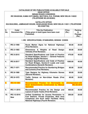
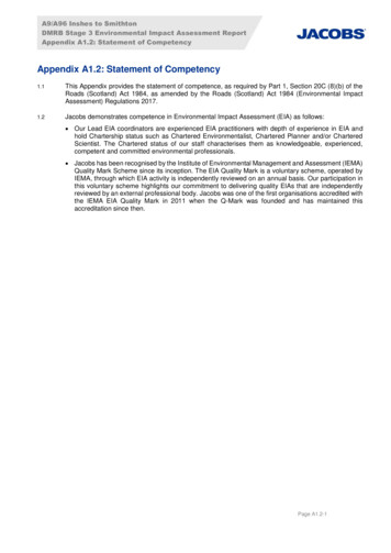
Section I: Routine Maintenance and Rehabilitation1Section I:Routine Maintenanceand RehabilitationUnderstanding RoadCross SectionEveryone involved in gravel road maintenance must understand the correctshape of the entire area within theroad’s right-of-way. Figure 1 shows atypical cross section of a gravel road.If states have minimum standards orpolicies for low-volume roads, theymust be followed.In order to maintain a gravel road properly, operators must clearly understandthe need for three basic items: acrowned driving surface, a shoulderarea that slopes directly away fromthe edge of the driving surface, and aditch. The shoulder area and the ditchof many gravel roads may be minimal.This is particularly true in regions withvery narrow or confined right-of-ways.Regardless of the location, the basicshape of the cross section must becorrect or a gravel road will not performwell, even under very low traffic.Paved roads are usually designed andthen constructed with careful consideration given to correct shape of the crosssection. Once paving is finished, theFigure 1: The components of the roadway cross section.roadway keeps its shape for an indefinite period of time. Gravel roads arequite different. Unfortunately, many ofthem are not constructed well initially.In addition, gravel roads tend to rutmore easily in wet weather. Traffic alsotends to displace gravel from the surface to the shoulder area and even tothe ditch during dry weather. Managersand equipment operators have the continual responsibility of keeping theroadway properly shaped. The shapeof the road surface and the shoulderarea is the equipment operator’sresponsibility and is classified asroutine maintenance.Keeping the foreslope and ditch established and shaped is often the maintenance operator’s responsibility as well.Obviously, the whole idea here is tokeep water drained away from theroadway. Standing water at any placewithin the cross section (including theditch) is one of the major reasons fordistress and failure of a gravel road.There is sometimes a need for specialized equipment to do major reshapingof the cross section,especially in verywet conditions. However, the operatorof routine maintenance equipment mustdo everything possible to take care of
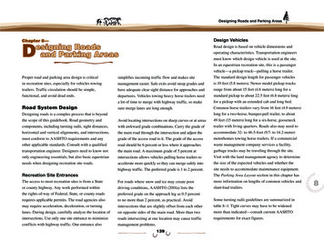
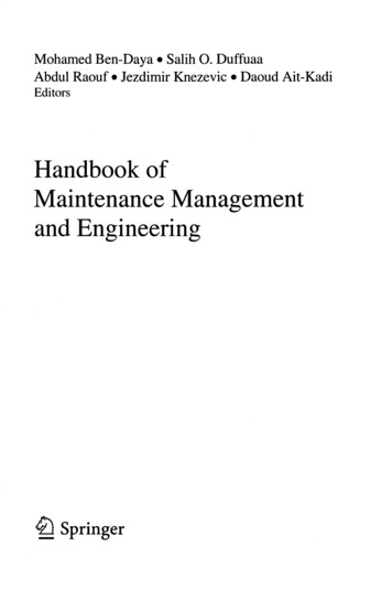
2Understanding Road Cross SectionThis road, located in Poland, has very poor cross section with noditches. Consequently, water drains down the roadway itself andafter many years of erosion,the roadway is several feet lowerthan its original elevation. (Courtesy of Mary O’Neill,Office ofRemote Sensing, South Dakota State University)This well-traveled road in Ecuador performswell in a region that receives approximately200 inches average annual rainfall.(Courtesy of Ron Anderson, TensarEarth Technologies, Inc.,USA)
Understanding Road Cross Section3the roadway since budgets often do notallow for the use of extra equipmentand manpower on gravel roads.The recommended shape of each partof the cross section will be discussed indetail later in this manual.When agravel road is maintained properly, itwill serve low volume traffic well.Unfortunately, most gravel roads willfail when exposed to heavy hauls evenwhen shaped properly. This is due toweak subgrade strength and marginalgravel depths which are often problemswith gravel roads. The low volume ofnormal traffic does not warrant reconstruction to a higher standard. However,improper maintenance can also leadto very quick deterioration of a gravelroad, especially in wet weather. Themaintenance equipment operators mustalways work at maintaining the propercrown and shape.Example of a gravel road with good shape of cross section. Notice crown in driving surface andproper shape of shoulder and ditch.An example of a well shaped gravel road shoulder that slopes away from the driving surfaceand drains water to the inslope and ditch.
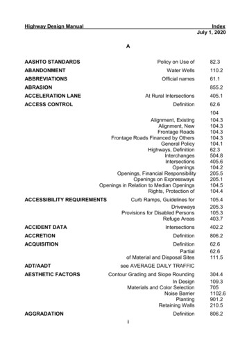
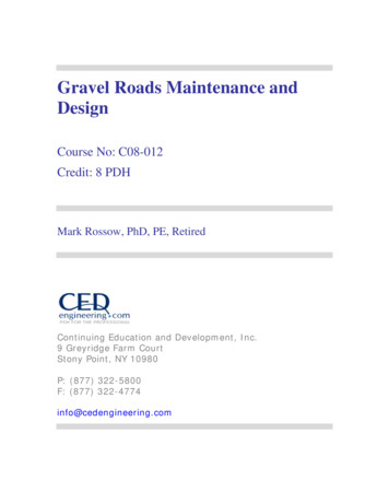
4Routine Shaping PrinciplesRoutine Shaping PrinciplesThe distortion that was cut into this roadsurface is the result of operating a motorgradertoo fast.The angle of the depressions whichmatch the angle of the moldboard reveal this.This is not the same as “washboarding,” whichhas different causes.Grader operator cleaning a ditch and restoringshape to the foreslope and backslope.he primary focus of this sectionwill be the use of the motorgraderfor gravel road maintenance. However,there are other devices used for thejob that can work well. Front or rearmounted grading attachments fortractors, road rakes, and other devicesof various designs are used in someareas of the country. The principles ofshaping are the same no matter whatmachine is used.TOperating SpeedOperating speed in blading operationsmust not be excessive. This has causedproblems on many roads. It is virtuallyimpossible to do good work above atop speed of 3 to 5 mph.When themachine begins to “lope” or bounce,it will cut depressions and leave ridgesin the road surface. Conditions includingmoisture, material, and subgrade stability vary; therefore, the maximum speedfor good maintenance can vary.However, in virtually any condition, it isdifficult to exceed 5 mph and still do agood job.Moldboard AngleThe angle of the moldboard is also critical to good maintenance. This angle isfixed on some grading devices, but onmotorgraders it can be easily adjusted.It is important to keep the angle somewhere between 30 and 45 degrees. It isa challenge to recover loose aggregate
Routine Shaping Principles5This is an example of poor use of the grader.The moldboard is pitched back too far and isnot angled enough.Notice the gravel builds upand does not fall forward to give a good mixingaction.Also, the loss of material from the toeof the moldboard will create a high shoulder,which destroys good drainage across theshoulder to the ditch.Moldboard pitch or “tilt” refers to how much themoldboard is tipped forward or backward.Theright pitch ranges from aggressive cutting (1), tospreading (2),to light blading or dragging action(3) for maintenance of gravel roads.12This is the other extreme of pitching themoldboard too far forward.The material will notroll across the face of the moldboard and doesnot mix.In addition to this, the cutting edge willnot easily penetrate a hard surface, making ithard to trim out even light depressions in theroad surface. It simply tends to skip along thesurface with no real benefit.3
6Routine Shaping PrinciplesNotice these examples of good pitch and angle. The gravelfalls forward and moves across the moldboard very well.The cutting edge is close to vertical from the road surface,which makes a nice light trimming action for routinemaintenance, and the angle is good,not allowingmaterial to spill from the toe of the moldboard.from the shoulder of the roadway without spilling material around the leadingedge (toe) of the moldboard. Operatingwithout enough angle is a primarycause of this spilling.Moldboard PitchAlong with correct angle, it is importantto understand proper pitch or “tilt” of amoldboard. If the moldboard is pitchedback too far, the material will tend tobuild up in front of the moldboard andwill not
Gravel Roads Maintenance and Design Course No: C08-012 Credit: 8 PDH Mark Rossow, PhD, PE, Retired Continuing Education and Development, Inc. 9 Greyridge Farm Court Stony Point, NY 10980 P: