Transcription
AeroDyn v15 User’s Guide andTheory ManualJ.M. Jonkman, G.J. Hayman, B.J. Jonkman,R.R. Damiani, R.E. MurrayNRELNREL is a national laboratory of the U.S. Department of EnergyOffice of Energy Efficiency & Renewable EnergyOperated by the Alliance for Sustainable Energy, LLCThis report is available at no cost from the National Renewable EnergyLaboratory (NREL) at www.nrel.gov/publications.Technical Report (Arial 11 pt Bold)NREL/TP-xxxx-xxxxxMonth Year (Arial 11 pt)Contract No. DE-AC36-08GO28308
AeroDyn v15 User’s Guide andTheory ManualJ.M. Jonkman, G.J. Hayman, B.J. Jonkman,R.R. Damiani, R.E. MurrayNRELPrepared under Task No(s). XXXX.XXXX, XXXX.XXXXNREL is a national laboratory of the U.S. Department of EnergyOffice of Energy Efficiency & Renewable EnergyOperated by the Alliance for Sustainable Energy, LLCThis report is available at no cost from the National Renewable EnergyLaboratory (NREL) at www.nrel.gov/publications.National Renewable Energy Laboratory15013 Denver West ParkwayGolden, CO 80401303-275-3000 www.nrel.govTechnical Report (Arial 11 pt Bold)NREL/TP-xxxx-xxxxxMonth Year (Arial 11 pt)Contract No. DE-AC36-08GO28308
NOTICEThis report was prepared as an account of work sponsored by an agency of the United States government.Neither the United States government nor any agency thereof, nor any of their employees, makes any warranty,express or implied, or assumes any legal liability or responsibility for the accuracy, completeness, or usefulness ofany information, apparatus, product, or process disclosed, or represents that its use would not infringe privatelyowned rights. Reference herein to any specific commercial product, process, or service by trade name,trademark, manufacturer, or otherwise does not necessarily constitute or imply its endorsement, recommendation,or favoring by the United States government or any agency thereof. The views and opinions of authorsexpressed herein do not necessarily state or reflect those of the United States government or any agency thereof.This report is available at no cost from the National Renewable EnergyLaboratory (NREL) at www.nrel.gov/publications.Available electronically at http://www.osti.gov/scitechAvailable for a processing fee to U.S. Department of Energyand its contractors, in paper, from:U.S. Department of EnergyOffice of Scientific and Technical InformationP.O. Box 62Oak Ridge, TN 37831-0062phone: 865.576.8401fax: 865.576.5728email: mailto:reports@adonis.osti.govAvailable for sale to the public, in paper, from:U.S. Department of CommerceNational Technical Information Service5285 Port Royal RoadSpringfield, VA 22161phone: 800.553.6847fax: 703.605.6900email: orders@ntis.fedworld.govonline ordering: http://www.ntis.gov/help/ordermethods.aspxCover Photos: (left to right) photo by Pat Corkery, NREL 16416, photo from SunEdison, NREL 17423, photo by Pat Corkery, NREL16560, photo by Dennis Schroeder, NREL 17613, photo by Dean Armstrong, NREL 17436, photo by Pat Corkery, NREL 17721.Printed on paper containing at least 50% wastepaper, including 10% post consumer waste.
1 NomenclatureFuture versions of the manual will include nomenclature used throughout the document.
2 IntroductionAeroDyn is a time-domain wind turbine aerodynamics module that has been coupled into theFAST version 8 multi-physics engineering tool to enable aero-elastic simulation of horizontalaxis turbines. AeroDyn can also be driven as a standalone code to compute wind turbineaerodynamic response uncoupled from FAST. When coupled to FAST, AeroDyn can also belinearized as part of the linearization of the full coupled solution (linearization is not available instandalone mode). AeroDyn was originally developed for modeling wind turbine aerodynamics,however, the module equally applies to the hydrodynamics of marine hydrokinetic (MHK)turbines (the terms “wind turbine”, “tower”, “aerodynamics” etc. in this document imply “MHKturbine”, “MHK support structure”, “hydrodynamics” etc. for MHK turbines). Additionalphysics important for MHK turbines, not applicable to wind turbines, computed by AeroDyninclude a cavitation check. This documentation pertains to the newest release of AeroDyn—version 15 and newer, which represents a complete overhaul from earlier version of AeroDyn.AeroDyn v15 and newer follows the requirements of the FAST modularization framework.AeroDyn calculates aerodynamic loads on both the blades and tower. Aerodynamic calculationswithin AeroDyn are based on the principles of actuator lines, where the three-dimensional (3D)flow around a body is approximated by local two-dimensional (2D) flow at cross sections, andthe distributed pressure and shear stresses are approximated by lift forces, drag forces, andpitching moments lumped at a node in a 2D cross section. Analysis nodes are distributed alongthe length of each blade and tower, the 2D forces and moment at each node are computed asdistributed loads per unit length, and the total 3D aerodynamic loads are found by integrating the2D distributed loads along the length. When AeroDyn is coupled to FAST, the blade and toweranalysis node discretization may be independent from the discretization of the nodes in thestructural modules. The actuator line approximations restrict the validity of the model to slenderstructures and 3D behavior is either neglected, captured through corrections inherent in themodel (e.g., tip-loss, hub-loss, or skewed-wake corrections), or captured in the input data (e.g.,rotational augmentation corrections applied to airfoil data).AeroDyn assumes the turbine geometry consists of a one-, two-, or three-bladed rotor atop asingle tower. While the undeflected tower is assumed to be straight and vertical, an undeflectedblade may consider out-of-plane curvature and in-plane sweep. For blades, the 2D cross sectionswhere the aerodynamic analysis takes place may follow the out-of-plane curvature, but in-planesweep is assumed to be accomplished by shearing, rather than rotation of the 2D cross section.Aerodynamic imbalances are possible through the use of geometrical differences between eachblade.When AeroDyn is coupled to FAST, AeroDyn receives the instantaneous (possiblydisplaced/deflected) structural position, orientation, and velocities of analysis nodes in the tower,hub, and blades. As with curvature and sweep, the 2D cross sections where the bladeaerodynamic analysis takes place will follow the out-of-plane deflection, but in-plane deflectionis assumed to be accomplished by shearing, rather than rotation of the 2D cross section.AeroDyn also receives the local freestream (undisturbed) fluid velocities at the tower and bladenodes. (Fluid and structural calculations take place outside of the AeroDyn module and arepassed as inputs to AeroDyn by the driver code.) The fluid and structural motions are providedat each coupling time step and then AeroDyn computes the aerodynamic loads on the blade and
tower nodes and returns them back to FAST as part of the aero-elastic calculation. In standalonemode, the inputs to AeroDyn are prescribed by a simple driver code, without aero-elasticcoupling.AeroDyn consists of four submodels: (1) rotor wake/induction, (2) blade airfoil aerodynamics,(3) tower influence on the fluid local to the blade nodes, and (4) tower drag. Nacelle, hub, andtail-vane fluid influence and loading, aeroacoustics, and wake and array effects between multipleturbines in a wind plant, are not yet available in AeroDyn v15 and newer.For operating wind and MHK turbine rotors, AeroDyn calculates the influence of the wake viainduction factors based on the quasi-steady Blade-Element/Momentum (BEM) theory, whichrequires an iterative nonlinear solve (implemented via Brent’s method). By quasi-steady, it ismeant that the induction reacts instantaneously to loading changes. The induction calculation,and resulting inflow velocities and angles, are based on flow local to each analysis node of eachblade, based on the relative velocity between the fluid and structure (including the effects oflocal inflow skew, shear, turbulence, tower flow disturbances, and structural motion, dependingon features enabled). The Glauert’s empirical correction (with Buhl’s modification) replaces thelinear momentum balance at high axial induction factors. In the BEM solution, Prandtl tip-loss,Prandtl hub-loss, and Pitt and Peters skewed-wake are all 3D corrections that can optionally beapplied. When the skewed-wake correction is enabled, it is applied after the BEM iteration.Additionally, the calculation of tangential induction (from the angular momentum balance), theuse of drag in the axial-induction calculation, and the use of drag in the tangential-inductioncalculation are all terms that can optionally be included in the BEM iteration (even when drag isnot used in the BEM iteration, drag is still used to calculate the nodal loads once the inductionhas been found). The wake/induction calculation can be bypassed altogether for the purposes ofmodeling rotors that are parked or idling, in which case the inflow velocity and angle aredetermined purely geometrically. During linearization analyses with AeroDyn coupled to FASTand BEM enabled, the wake can be assumed to be frozen (i.e. the axial and tangential induces Vx a and Vy a ' , are fixed at their operating-point values during linearization) or thevelocities,induction can be recalculated during linearization using BEM theory. Dynamic wake thataccounts for induction dynamics as a result of transient conditions are not yet available inAeroDyn v15 and newer.The blade airfoil aerodynamics can be steady or unsteady, except in the case that a cavitationcheck is requested for MHK in which case only steady aerodynamics are supported. In the steadymodel, the supplied static airfoil data—including the lift-force, drag-force, and optional pitchingmoment and minimum pressure coefficients versus angle of attack (AoA)—are used directly tocalculate nodal loads. The AirfoilPrep preprocessor can be used to generate the needed staticairfoil data based on uncorrected 2D data (based e.g. on airfoil tests in a wind tunnel or XFoil),including features to blend data between different airfoils, apply 3D rotational augmentation, andextrapolate to high AoA. The unsteady airfoil aerodynamic (UA) models account for flowhysteresis, including unsteady attached flow, trailing-edge flow separation, dynamic stall, andflow reattachment. The UA models can be considered as 2D dynamic corrections to the staticairfoil response as a result of time-varying inflow velocities and angles. Three semi-empiricalUA models are available: the original theoretical developments of Beddoes-Leishman (B-L),extensions to the B-L developed by González, and extensions to the B-L model developed by
Minnema/Pierce. While all of the UA models are documented in this manual, the original BL model is not yet functional. Testing has shown that the González and Minnema/Piercemodels produce reasonable hysteresis of the normal force, tangential force, and pitchingmoment coefficients if the UA model parameters are set appropriately for a given airfoil,Reynold’s number, and/or Mach number. However, the results will differ a bit fromearlier versions of AeroDyn, (which was based on the Minnema/Pierce extensions to B-L)even if the default UA model parameters are used, due to differences in the UA model logicbetween the versions. We recommend that users run test cases with uniform wind inflowand fixed yaw error (e.g., through the standalone AeroDyn driver) to examine the accuracyof the normal force, tangential force, and pitching-moment coefficient hysteresis and toadjust the UA model parameters appropriately. The airfoil-, Reynold’s-, and Machdependent parameters of the UA models may be derived from the static airfoil data. These UAmodels are valid for small to moderate AoA under normal rotor operation; the steady model ismore appropriate under parked or idling conditions. The static airfoil data is always used in theBEM iteration; when UA is enabled, it is applied after the BEM iteration and after the skewedwake correction. The UA models are not set up to support linearization, so, UA must be disabledduring linearization analyses with AeroDyn coupled to FAST. The interpolation of airfoil databased on Reynolds number or aerodynamic-control setting (e.g., flaps) is not yet available inAeroDyn v15 and newer.The influence of the tower on the fluid flow local to the blade is based on a potential-flow and/ora tower shadow model. The potential-flow model uses the analytical potential-flow solution forflow around a cylinder to model the tower dam effect on upwind rotors. In this model, thefreestream (undisturbed) flow at each blade node is disturbed based on the location of the bladenode relative to the tower and the tower diameter, including lower velocities upstream anddownstream of the tower, higher velocities to the left and right of the tower, and cross-streamflow. The Bak correction can optionally be included in the potential-flow model, whichaugments the tower upstream disturbance and improves the tower wake for downwind rotorsbased on the tower drag coefficient. The tower shadow model can also be enabled to account forthe tower wake deficit on downwind rotors. This model includes an axial flow deficit on thefreestream fluid at each blade node dependent on the location of the blade node relative to thetower and the tower diameter and drag coefficient, based on the work of Powles. Both towerinfluence models are quasi-steady models, in that the disturbance is applied directly to thefreestream fluid at the blade nodes without dynamics, and are applied within the BEM iteration.The aerodynamic load on the tower is based directly on the tower diameter and drag coefficientand the local relative fluid velocity between the freestream (undisturbed) flow and structure ateach tower analysis node (including the effects of local shear, turbulence, and structural motion,depending on features enabled). The tower drag load calculation is quasi-steady and independentfrom the tower influence on flow models.The primary AeroDyn input file defines modeling options, environmental conditions (exceptfreestream flow), airfoils, tower nodal discretization and properties, as well as output filespecifications. Airfoil data properties are read from dedicated inputs files (one for each airfoil)and include coefficients of lift force, drag force, and optional pitching moment and minimumpressure versus AoA, as well as UA model parameters. (Minimum pressure coefficients versusAoA are also included in the airfoil input files in case that a cavitation check is requested.) Blade
nodal discretization, geometry, twist, chord, and airfoil identifier are likewise read from separateinput files (one for each blade).Section 3 details how to obtain the AeroDyn and FAST software archives and how to run boththe standalone AeroDyn or AeroDyn coupled to FAST. Section 4 describes the AeroDyn inputfiles. Section 5 discusses the output files generated by AeroDyn; these include an echo file,summary file, and the results file. Section 6 provides modeling guidance when using AeroDyn.The AeroDyn theory is covered in Section 7. Section 8 outlines future work, and Section 9contains a list of references. Example input files are shown in Appendix A through D. Asummary of available output channels are found in Appendix E. Appendix F tracks the majorchanges we have made to AeroDyn for each public release.
3 Running AeroDyn3.1 Downloading the AeroDyn Software3.1.1 Standalone AeroDyn ArchiveYou can download the standalone AeroDyn archive from our web server athttps://nwtc.nrel.gov/AeroDyn. The file has a name similar to AD v15.00.00.exe, but may have adifferent version number. Run the downloaded self-extracting archive (.exe) to expand thearchive into a folder you specify.The archive contains the bin, CertTest, and Documentation folders. The bin folder includes theAeroDyn Driver.exe, which is used to execute the standalone AeroDyn program. The CertTestfolder contains sample AeroDyn input files for wind and MHK applications. This manual may befound in the Documentation folder.3.1.2 FAST ArchiveYou can download the FAST archive, which includes a coupling to AeroDyn, from our webserver at https://nwtc.nrel.gov/FAST8. The file has a name similar to FAST v8.12.00.exe, butmay have a different version number. Run the downloaded self-extracting archive (.exe) toexpand the archive into a folder you specify. The FAST executable is located in the archive’sbin folder. Example models are located in the CertTest folder.3.2 Running the Standalone AeroDynThe standalone AeroDyn program, AeroDyn Driver.exe, simulates aerodynamic responses ofyour input model, without coupling to FAST. Unlike the coupled version, the standalonesoftware requires the use of a driver file in addition to the primary AeroDyn, airfoil, and bladeinput files. This driver file specifies initialization inputs normally provided to AeroDyn byFAST, as well as the per-time-step inputs to AeroDyn. Both the AeroDyn summary file and theresults output file are available when using the standalone AeroDyn; see Section 5 for moreinformation regarding the AeroDyn output files.The AeroDyn standalone program can be run in two ways:
1) Run the standalone AeroDyn software from a DOS command prompt by typing, e.g. AeroDyn Driver.exe MyDriverFile.dvrwhere, MyDriverFile.dvr is the name of the AeroDyn driver file, as described in Section4.2.2) Run the standalone AeroDyn software from the MATLAB or Python scripts included inthe AeroDyn archive folder. To do this, open the MATLAB or Python script and updatethe name of the driver file you wish you execute. The interface scripts in the samples alsogive examples of loading and plotting the outputs requested by the user.The AeroDyn primary, airfoil, and blade input files are described in Sections 4.3, 4.4, and 4.5,respectively.3.3 Running AeroDyn Coupled to FASTRun the coupled FAST software from a DOS command prompt by typing, e.g. FAST win32.exe Test18.fstwhere, Test18.fst is the name of the primary FAST input file. This input file has a control flag toturn on or off the AeroDyn capabilities within FAST, and a corresponding reference to theprimary AeroDyn input file. See the documentation supplied with FAST for further information.
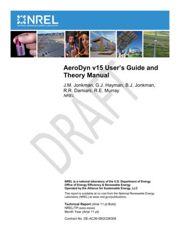
4 Input FilesThe user configures the aerodynamic model parameters via a primary AeroDyn input file, as wellas separate input files for airfoil and blade data. When used in standalone mode, an additionaldriver input file is required. This driver file specifies initialization inputs normally provided toAeroDyn by FAST, as well as the per-time-step inputs to AeroDyn.As an example, in the CertTest folder in the AeroDyn archive, the XXX driver.dvr file is themain driver, the XXX input.dat is the primary input file, the XXX blade.dat file contains theblade geometry data, and the XXX airfoil.dat file contains the airfoil angle of attack, lift, drag,moment coefficients, and pressure coefficients.No lines should be added or removed from the input files, except in tables where the number ofrows is specified and comment lines in the AeroDyn airfoil data files.4.1 UnitsAeroDyn uses the SI system (kg, m, s, N). Angles are assumed to be in radians unless otherwisespecified.4.2 AeroDyn Driver Input FileThe driver input file is only needed for the standalone version of AeroDyn and contains inputsnormally generated by FAST, and necessary to control the aerodynamic simulation foruncoupled models. A sample AeroDyn driver input file is given in Appendix A.Set the Echo flag in this file to TRUE if you wish to have AeroDyn Driver.exe echo the contentsof the driver input file (useful for debugging errors in the driver file). The echo file has thenaming convention of OutFileRoot.ech, where OutFileRoot is specified in the I/O SETTINGSsection of the driver input file below. AD InputFile is the filename of the primary AeroDyninput file. This name should be in quotations and can contain an absolute path or a relative path.The TURBINE DATA section defines the AeroDyn-required turbine geometry for a rigidturbine, see Figure 1. NumBlades specifies the number of blades; only one-, two-, or threebladed rotors are permitted. HubRad specifies the radius to the blade root from the center-ofrotation along the (possibly preconed) blade-pitch axis; HubRad must be greater than zero.HubHt specifies the elevation of the hub center above the ground (or above the mean sea level(MSL) for offshore wind turbines or above the seabed for MHK turbines). Overhang specifiesthe distance along the (possibly tilted) rotor shaft between the tower centerline and hub center;Overhang is positive downwind, so use a negative number for upwind rotors. ShftTilt is theangle (in degrees) between the rotor shaft and the horizontal plane. Positive ShftTilt means thatthe downwind end of the shaft is the highest; upwind turbines have negative ShftTilt forimproved tower clearance. Precone is the angle (in degrees) between a flat rotor disk and thecone swept by the blades, positive downwind; upwind turbines have negative Precone forimproved tower clearance.
The I/O SETTINGS section controls the creation of the results file. If OutFileRoot is specified,the results file will have the filename OutFileRoot.#.out, where the ‘#’ character is an integernumber corresponding to a test case line found in the COMBINED-CASE ANALYSIS sectiondescribed below. If an empty string is provided for OutFileRoot, then the driver file’s root namewill be used instead. If TabDel is TRUE, a TAB character is used between columns in theoutput file; if FALSE, fixed-width is used otherwise. OutFmt is any valid Fortran numericformat string, which is used for text output, excluding the time channel. The resulting fieldshould be 10 characters, but AeroDyn does not check OutFmt for validity. If you want a soundgenerated on program exit, set Beep to true.
Precone(negative as shown)Blade-Pitch AxisRotor PlaneBlade RootHubRadOverhang(negative as shown)Wind .ShftTilt(negative as shown)Hub CenterHubHtRotor-Shaft AxisTower CenterlineFigure 1. AeroDyn Driver Turbine GeometryThe COMBINED-CASE ANALYSIS section allows you to execute NumCases number ofsimulations for the given TURBINE DATA with a single driver input file. There will be one
row in the subsequent table for each of the NumCases specified (plus two table header lines).The information within each row of the table fully specifies each simulation. Each row containsthe following columns: WndSpeed, ShearExp, RotSpd, Pitch, Yaw, dT, and Tmax. The localundisturbed wind speed for any given blade or tower node is determined using, Z U ( Z ) WndSpeed HubHt ShearExp,where WndSpeed is the steady wind speed (fluid flow speed in the case of an MHK turbine)located at elevation HubHt, Z is the instantaneous elevation of the blade or tower node above theground (or above the MSL for offshore wind turbines or above the seabed for MHK turbines),and ShearExp is the power-law shear exponent. The fixed rotor speed (in rpm) is given byRotSpd (positive clockwise looking downwind), the fixed blade-pitch angle (in degrees) is givenby Pitch (positive to feather, leading edge upwind), and the fixed nacelle-yaw angle (in degrees)is given by Yaw (positive rotation of the nacelle about the vertical tower axis, counterclockwisewhen looking downward). While the flow speed and direction in the AeroDyn driver is uniformand fixed (depending only on elevation above ground), Yaw and ShftTilt (from the TURBINEDATA section above) can introduce skewed flow. dT is the simulation time step, which mustmatch the time step for the aerodynamic calculations (DTAero) as specified in the primaryAeroDyn input file, and Tmax is the total simulation time.4.3 AeroDyn Primary Input FileThe primary AeroDyn input file defines modeling options, environmental conditions (exceptfreestream flow), airfoils, tower nodal discretization and properties, as well as output filespecifications.The file is organized into several functional sections. Each section corresponds to an aspect ofthe aerodynamics model. A sample AeroDyn primary input file is given in Appendix B.The input file begins with two lines of header information which is for your use, but is not usedby the software.4.3.1 General OptionsSet the Echo flag to TRUE if you wish to have AeroDyn echo the contents of the AeroDynprimary, airfoil, and blade input files (useful for debugging errors in the input files). The echofile has the naming convention of OutRootFile.AD.ech. OutRootFile is either specified in theI/O SETTINGS section of the driver input file when running AeroDyn standalone, or by theFAST program when running a coupled simulation.DTAero sets the time step for the aerodynamic calculations. For accuracy and numericalstability, we recommend that DTAero be set such that there are at least 200 azimuth steps perrotor revolution. However, when AeroDyn is coupled to FAST, FAST may require time stepsmuch smaller than this rule of thumb. If UA is enabled while using very small time steps, youmay need to recompile AeroDyn in double precision to avoid numerical problems in the UAroutines. The keyword ‘DEFAULT’ for DTAero may be used to indicate that AeroDyn shouldemploy the time step prescribed by the driver code (FAST or the standalone driver program).
Set WakeMod to 0 if you want to disable rotor wake/induction effects or 1 to include theseeffects using the BEM theory model. Set AFAeroMod to 1 to include steady blade airfoilaerodynamics or 2 to enable UA; AFAeroMod must be 1 during linearization analyses withAeroDyn coupled to FAST. Set TwrPotent to 0 to disable the potential-flow influence of thetower on the fluid flow local to the blade, 1 to enable the standard potential-flow model, or 2 toinclude the Bak correction in the potential-flow model. Set the TwrShadow flag to TRUE toinclude the influence of the tower on the flow local to the blade based on the downstream towershadow model or FALSE to disable these effects. If the tower influence from potential flow andtower shadow are both enabled, the two influences will be superimposed. Set the TwrAero flagto TRUE to calculate fluid drag loads on the tower or FALSE to disable these effects. Duringlinearization analyses with AeroDyn coupled FAST and BEM enabled (WakeMod 1), set theFrozenWake flag to TRUE to employ frozen-wake assumptions during linearization (i.e. to fixV a' V athe axial and tangential induces velocities, x and y , at their operating-point values duringlinearization) or FALSE to recalculate the induction during linearization using BEM theory. Setthe CavitCheck flag to TRUE to perform a cavitation check for MHK turbines or FALSE todisable this calculation. If CavitCheck is TRUE, AFAeroMod must be set to 1 because thecavitation check does not function with unsteady airfoil aerodynamics.4.3.2 Environmental ConditionsAirDens specifies the fluid density and must be a value greater than zero; a typical value isaround 1.225 kg/m3 for air (wind turbines) and 1025 kg/m3 for seawater (MHK turbines).KinVisc specifies the kinematic viscosity of the air (used in the Reynolds number calculation); atypical value is around 1.460E-5 m2/s for air (wind turbines) and 1.004E-6 m2/s for seawater(MHK turbines). SpdSound is the speed of sound in air (used to calculate the Mach numberwithin the unsteady airfoil aerodynamics calculations); a typical value is around 340.3 m/s. Thelast three parameters in this section are only used when CavitCheck TRUE for MHK turbines.Patm is the atmospheric pressure above the free surface; typically around 101,325 Pa. Pvap isthe vapor pressure of the fluid; for seawater this is typically around 2,000 Pa. FluidDepth is thedistance from the hub center to the free surface.4.3.3 Blade-Element/Momentum TheoryThe input parameters in this section are only used when WakeMod 1.SkewMod determines the skewed-wake correction model. Set SkewMod to 1 to use theuncoupled BEM solution technique without an additional skewed-wake correction. SetSkewMod to 2 to include the Pitt/Peters correction model. The coupled model (SkewMod 3)is not available in this version of AeroDyn.Set TipLoss to TRUE to include the Prandtl tip-loss model or FALSE to disable it. Likewise, setHubLoss to TRUE to include the Prandtl hub-loss model or FALSE to disable it.Set TanInd to TRUE to include tangential induction (from the angular momentum balance) inthe BEM solution or FALSE to neglect it. Set AIDrag to TRUE to include drag in the axialinduction calculation or FALSE to neglect it. If TanInd TRUE, set TIDrag to TRUE toinclude drag in the tangential-induction calculation or FALSE to neglect it. Even when drag is
not used in the BEM iteration, drag is still used to calculate the nodal loads once the inductionhas been found,IndToler sets the convergence threshold for the iterative nonlinear solve of the BEM solution.The nonlinear solve is in terms of the inflow angle, but IndToler represents the tolerance of thenondimensional residual equation, with no physical association possible. When the keyword‘DEFAULT’ is used in place of a numerical value, IndToler will be set to 5E-5 when AeroDynis compiled in single precision and to 5E-10 when AeroDyn is compiled in double precision; werecommend using these defaults. MaxIter determines the maximum number of iterations stepsin the BEM solve. If the residual value of the BEM solve is not less than or equal to IndToler inMaxIter, AeroDyn will exit the BEM solver and return an error message.4.3.4 Unsteady Airfoil Aerodynamics OptionsThe input parameters in this section are only used when AFAeroMod 2.UAMod determines the UA model. Setting UAMod to 1 enables original theoreticaldevelopments of B-L, 2 enables the extensions to B-L developed by González, and 3 enables theextensions to B-L developed by Minnema/Pierce. While all of the UA model
Future versions of the manual will include nomenclature used throughout the document. 2 Introduction AeroDyn is a time-domain wind turbine aerodynamics module that has beencoupled into the FAST version 8 multi-physics engineering tool to enable aero-elastic simulation of horizontal-