Transcription
Massachusetts Institute of TechnologyDepartment of Mechanical EngineeringCambridge, MA 021392.002 Mechanics and Materials IISpring 2004Laboratory Module No. 5Heat Treatment ofPlain Carbon and Low Alloy Steels:Effects on Macroscopic Mechanical Properties.1Background and ObjectivesIron is one of the oldest known metals, and carbon is the cheapest and most effectivealloying element for hardening iron. Iron Carbon alloys are known as “carbon steels”and account for more than 70% of the tonnage of metallic materials used in the UnitedStates for engineering applications. Carbon is added to iron in quantities ranging from0.04 to 2 wt% to make low, medium, and high carbon steels. The microstructure andresulting mechanical properties of these steels are amenable to modification via heattreatment, and a wide range of mechanical properties can be obtained by proper vari ations of heating and cooling cycles. Modest amounts (up to a few wt% percent each)of costlier alloying elements such as nickel, chromium, manganese, and molybdynum canbe added to the composition, resulting in “low alloy” [content] steels that possess addi tional desirable properties, including achievability of high strength and good ductility inlarger sections.In this laboratory module we will demonstrate the essential steps involved in the heattreatment of a medium carbon steel, AISI 1045 (Fe 0.45 wt % C 0.75 wt % Mn 0.2 wt % Si), and a low alloy steel, AISI 4140 (Fe 0.40 wt % C 0.75 wt % Mn 0.2wt % Si 1.0 wt % Cr 0.2 wt % Mo), and measure macroscopic mechanical propertiesof the materials after different heat treatments.1
2Lab TasksIn this laboratory module we will perform the following tasks: Introduce, in elementary terms, essential steps involved in the heat treatment ofcarbon and low alloy steels, and briefly discuss aspects of the underlying materialsscience. Demonstrate austenitizing, annealing, quenching, and tempering heat treatingprocedures for AISI 1045 and/or AISI 4140 steels. Conduct mechanical tests on specimens of 1045 and/or 4140 steels which have beensubjected to four different heat treatment procedures:1. As received (normalized);2. Austenitized and slow cooled (annealed);3. Austenitized and water quenched; and4. Austenitized, water quenched, and tempered.For each material condition and associated microstructure we will perform:1. A tensile test,2. A Rockwell hardness test.Also, in order to get a tangible perception of the relative properties of the threematerial conditions, we will manually bend rods and compare the relative loadsrequired to initiate plastic deformation.3. A Charpy U notch impact test. We will discuss the correlations between the measured mechanical properties (strength,hardness, ductility, impact energy) in the various heat treated conditions.2
3Lab Assignment: Specific Questions to Answer1. Describe the heat treatment processes of 1045 (or 4140) steel introduced during thelaboratory session.2. Typical tensile stress strain behavior for 1045 steel, in the four conditions con sidered, will be generated. From these curves for each of the four heated treatedmaterial states, obtain the following tensile properties:(a) Young’s modulus, E;(b) Tensile yield strength (0.2 percent offset), σy ;(c) Ultimate tensile strength, σUTS ;(d) The reduction in area at fracture, q (A0 Af )/A0 where A0 originalcross sectional area, and Af final cross sectional area of the tensile testspecimens. Note that q is a measure of ductility, or plastic strain to failure.(e) Based on the Rockwell hardness data collected during the lab session, esti (HRC)mate the ultimate tensile strength σUTS of the alloy in the three conditionsconsidered. To complete this task use the conversion charts attached to thishandout.(f) Tabulate, for each microstructural state, the tensile properties, (E, σy , σUTS , q),(HRC)the Rockwell hardness and corresponding estimated tensile strength σUTS ,(Charpy)and the Charpy U notch impact energy (EU) data.3. Identify trends in the data. In particular, how do the moduli, strength, ductility,hardness and impact energy change with heat treatment?(HRC)4. How well does the hardness estimated tensile strength, σUTS , compare with theactually measured tensile strength, σUTS ? In particular, what is the source of dis crepancy for the data from the austenitized and quenched condition? (Hint: Doesthe compressive yield strength correlate better with the hardness estimated “tensilestrength” in those cases where there is a major discrepancy between the estimateand the maximum measured stress in the tensile test?)5. Over the set of lab sections, data was obtained for the quenched and temperedcondition using a range of tempering temperatures (see the web page for a summaryof the results). Identify and discuss trends in the resulting properties with respectto the tempering temperature.3
4Introduction to Heat Treatment of Plain Carbonand Low Alloy SteelsAdditional reference material: Dowling, Section 3.3It is perhaps presumptuous to attempt even a cursory synopsis of the vast literaturesurrounding the heat treatment of carbon and low alloy steels. There are at least twolevels at which the subject can be approached. One level constitutes a phenomenologicaldescription of what thermal histories are applied, along with details such as temperaturelevels, times of holding at temperature, maximum allowable time limits for executing“rapid” temperature changes, and technical nomenclature associated with the processes.A second, and more ambitious level focuses on fundamental physical processes, equi librium states of matter under different temperatures, and kinetics of the processes bywhich one state transforms to another under changes in temperature. The second levelis based on fundamentals of thermodynamics, kinetics, and materials science which cannot be easily (or effectively) introduced in a brief format such as the present laboratorymodule. Nonetheless, we will attempt to highlight “major aspects” of the heat treatingcarbon and low alloy steels from both the phenomenological/technological and the sci entific/academic points of view.The first notion of importance is that of equilibrium state of a collection of matter. Weare familiar with the changes of state of a pure substance like water, as a function oftemperature: at sufficiently low temperatures, (below 0 C), the stable, equilibrium stateis a solid (ice), while at ambient pressure and higher temperatures, water is liquid. Whatmay not be as well appreciated is that the equilibrium crystal microstructure of ice isnot constant, but depends on temperature and pressure.And so it is with the solid states of the substance pure iron (Fe):1. At ambient pressure and temperatures between 1394C and 1534C (the latter ofwhich is the melting temperature of pure Fe), its equilibrium phase is a body centered cubic (BCC) crystal called δ iron;2. At temperatures in the range 912C to 1394C, the stable phase is a face centeredcubic (FCC) phase called γ iron;3. While at temperature from absolute zero to 912C, the equilibrium phase is a BCCcrystal structure called α iron.For our purposes, only the temperature ranges corresponding to stable α and γ phasesare of interest.4
When iron is alloyed with carbon (C), in concentrations corresponding to 0.04 wt% to2.0 wt% one obtains “carbon steels”. In this case, an essential question is: “What happensto the carbon atoms in the iron crystal structures? ” Broadly speaking, there are twoplaces for the carbon atoms to go:1. They can dissolve in solid solution into the Fe crystal structure (either BCC γ orFCC α), leading to a single phase (crystal with dissolved C):(a) When the C is dissolved into the γ crystal phase of Fe, it is termed austenite:solid solution C in FCC iron;(b) When the C is dissolved into the α crystal phase of Fe, it is termed ferrite:solid solution C in BCC iron.2. Alternatively, carbon atoms can form a chemical reaction with iron atoms, forminga crystalline second phase iron carbide compound, Fe3 C, called cementite, whichprecipitates out into spatial regions separate from the solid solution phase. Ingeneral, this carbide is more resistant to plastic deformation than the iron/carbonsolid solution.The “equilibrium” structure of polycrystalline low carbon steels at low temperature istwo phase: there are spatial regions of the cementite compound (Fe3 C) distributed withinferrite crystals (α); the resulting two phase microstructure is sometimes denoted by “α Fe3 C”. A map of the relevant portion of the equilibrium phase diagram for theFe C system is shown in Figure 1, showing the combinations of temperature (verticalaxis) and carbon weight percent (horizontal axis) leading to the various equilibriummicrostructures.5
Image removed due to copyright considerations. See Figure 11.1 in Ashby, M. F, andD.R.H. Jones. Engineering Materials 2: An Introduction to Microstructures, Processingand Design. Elmsford NY: Pergamon, 1986.The most important single fact about the iron carbon system is that the solubility of Cis γ iron is very much larger than its solubility in α iron. (The maximum possibleequilibrium C content in α iron is only 0.0218 wt %, occurring at 723 C, as shownin Fig. 1.) This fact is exploited in constructing heat treatment thermal histories thatproduce special microstructures in carbon steels; in turn, these distinct microstructuresendow the heat treated steel with distinct material properties.Some common heat treatments for low and medium carbon steels:1. Austenitize and Air Cool:This is the typical heat treatment given to the steel by the manufacturer, and isaccordingly termed the as received condition. The thermal history leading to thisstate is also called normalizing. Normalizing of 1045 steel typically consists ofthe following steps: Austenitize: put in furnace at 850C in the austenite range, and hold for 16
hour until equilibrium temperature and corresponding solid solution structurehave been reached. Air cool: remove from furnace and allow to air cool to room temperature.2. Austenitize and Furnace Cool:This heat treatment is sometimes also called annealing. Here the steel is subjectedto the following temperature histories: Austenitize: put in furnace at 850C in the austenite range, and hold for 1hour until equilibrium temperature and corresponding solid solution structurehave been reached. Furnace Co ol: slowly cool in the furnace, from 850C to 700C, over a periodof 10 hours. Air cool: remove from furnace and allow to air cool to room temperature.3. Austenitize and Quench: Austenitize: put in furnace at 850C in the austenite range, and hold for 1hour until equilibrium temperature and corresponding solid solution structurehave been reached. Quench: Rapidly remove material from furnace, plunge it into a large reser voir of water at ambient temperature, and stir vigorously.For 1045 steel, the quenching medium is water at ambient temperature (forother steels, other quenching media such as oil or brine are used).4. Austenitize, Quench, and Temper: Austenitize: put in furnace at 850C in the austenite range, and hold for 1hour until equilibrium temperature has been reached. Quench: Rapidly remove material from furnace, plunge it into a large reser voir of water at ambient temperature, and stir vigorously. Temper: Re heat the steel to to the tempering temperature (example:250C), and hold for approximately 2 hours. Note: there is a range of possibletempering temperatures; for 1045 steel, this range is approximately from 200Cto 500C. Different tempering temperatures lead to differences in the resultingmechanical properties; in general, ‘lower’ tempering temperatures lead to highyield strength, but lower toughness and ductility, while ‘higher’ temperingtemperatures lower strength, but increase toughness and ductility. Air cool: remove from furnace and allow to air cool to room temperature.7
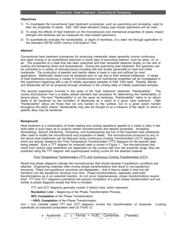
Each of these thermal histories produces unique microstructural conditions in the steel,and in turn, each microstructural state exhibits a unique combination of mechanicalproperties. We will perform the heat treatments, and measure the resulting mechanicalproperties.Notes on successful quenchingWe described the quenching process exclusively from the phenomenological/technologicalperspective, noting only that the process should be performed “rapidly” and that the partshould be “stirred vigorously” in the quenching liquid. Left unaddressed were quantita tive details of the resulting rapid temperature change: “what temperature[s] must thesteel reach, and within what amount[s] of time, in order for the quench to be successful?”In order to provide a satisfactory answer to such a question, it is necessary to look brieflyat the quenching process from the materials science perspective.Referring again to Fig. 1, suppose that our 0.45 wt % carbon steel is cooled moderatelyfast through both the so called A3 temperature separating the γ and γ α domains. ( ca870C for this carbon content) and the A1 temperature (723 C) below which a microstruc tural ‘composite’ of α F e3 C becomes the equilibrium phase. At temperatures aboveA3 , the C was homogeneously distributed in solid solution γ, but F e3 C is carbon rich(6.67 wt %), while the α will hold increasingly less C as temperature decreases below A1 .Thus, there must be diffusive mass transport of C from surrounding regions towardthe sites which will be occupied by the F e3 C compound. This takes time; for slow cool ing, there is ample time for transport, and equilibrium is achieved. But diffusion is alsothermally activated: it proceeds exponentially faster with increasing absolute tempera ture (rate e Q/kT , where T is absolute temperature, k is Boltzmann’s constant, and Qis activation energy for diffusion). If the temperature could be brought low enough, fastenough, so that negligible C transport had taken place, we would reach a meta stablestate in which BCC α crystals were “supersaturated” with 0.
3 Lab Assignment: Specific Questions to Answer 1. Describe the heat treatment processes of 1045 (or 4140) steel introduced during the laboratory session. 2. Typical tensile stress strain behavior for 1045 steel, in the four conditions con sidered, will be generated. From these curves for
