Transcription
NASA/CR—2009-215681Use of Cumulative Degradation Factor Predictionand Life Test Result of the Thruster GimbalAssembly Actuator for the Dawn Flight ProjectC. John LoNorthrop Grumman Aerospace Systems, Redondo Beach, CaliforniaJohn R. Brophy, M. Andy Etters, and Rajeshuni RameshamJet Propulsion Laboratory, Pasadena, CaliforniaWilliam R. Jones, Jr.Sest Inc., Middleburg Heights, OhioMark J. JansenUniversity of Toledo, Toledo, OhioOctober 2009
NASA STI Program . . . in ProfileSince its founding, NASA has been dedicated to theadvancement of aeronautics and space science. TheNASA Scientific and Technical Information (STI)program plays a key part in helping NASA maintainthis important role.The NASA STI Program operates under the auspicesof the Agency Chief Information Officer. It collects,organizes, provides for archiving, and disseminatesNASA’s STI. The NASA STI program provides accessto the NASA Aeronautics and Space Database andits public interface, the NASA Technical ReportsServer, thus providing one of the largest collectionsof aeronautical and space science STI in the world.Results are published in both non-NASA channelsand by NASA in the NASA STI Report Series, whichincludes the following report types: TECHNICAL PUBLICATION. Reports ofcompleted research or a major significant phaseof research that present the results of NASAprograms and include extensive data or theoreticalanalysis. Includes compilations of significantscientific and technical data and informationdeemed to be of continuing reference value.NASA counterpart of peer-reviewed formalprofessional papers but has less stringentlimitations on manuscript length and extent ofgraphic presentations.TECHNICAL MEMORANDUM. Scientificand technical findings that are preliminary orof specialized interest, e.g., quick releasereports, working papers, and bibliographies thatcontain minimal annotation. Does not containextensive analysis.CONTRACTOR REPORT. Scientific andtechnical findings by NASA-sponsoredcontractors and grantees. CONFERENCE PUBLICATION. Collectedpapers from scientific and technicalconferences, symposia, seminars, or othermeetings sponsored or cosponsored by NASA. SPECIAL PUBLICATION. Scientific,technical, or historical information fromNASA programs, projects, and missions, oftenconcerned with subjects having substantialpublic interest. TECHNICAL TRANSLATION. Englishlanguage translations of foreign scientific andtechnical material pertinent to NASA’s mission.Specialized services also include creating customthesauri, building customized databases, organizingand publishing research results.For more information about the NASA STIprogram, see the following: Access the NASA STI program home page athttp://www.sti.nasa.gov E-mail your question via the Internet to help@sti.nasa.gov Fax your question to the NASA STI Help Deskat 443–757–5803 Telephone the NASA STI Help Desk at443–757–5802 Write to:NASA Center for AeroSpace Information (CASI)7115 Standard DriveHanover, MD 21076–1320
NASA/CR—2009-215681Use of Cumulative Degradation Factor Predictionand Life Test Result of the Thruster GimbalAssembly Actuator for the Dawn Flight ProjectC. John LoNorthrop Grumman Aerospace Systems, Redondo Beach, CaliforniaJohn R. Brophy, M. Andy Etters, and Rajeshuni RameshamJet Propulsion Laboratory, Pasadena, CaliforniaWilliam R. Jones, Jr.Sest Inc., Middleburg Heights, OhioMark J. JansenUniversity of Toledo, Toledo, OhioPrepared under Contract NNC07JF14TNational Aeronautics andSpace AdministrationGlenn Research CenterCleveland, Ohio 44135October 2009
AcknowledgmentsThis research was carried out in part, at the Jet Propulsion Laboratory, California Institute of Technology in Pasadena,California, under Contract Task Plan Number 40–12079 with the National Aeronautics and Space Administration.Trade names and trademarks are used in this report for identificationonly. Their usage does not constitute an official endorsement,either expressed or implied, by the National Aeronautics andSpace Administration.Level of Review: This material has been technically reviewed by NASA technical management OR expert reviewer(s).Available fromNASA Center for Aerospace Information7115 Standard DriveHanover, MD 21076–1320National Technical Information Service5285 Port Royal RoadSpringfield, VA 22161Available electronically at http://gltrs.grc.nasa.gov
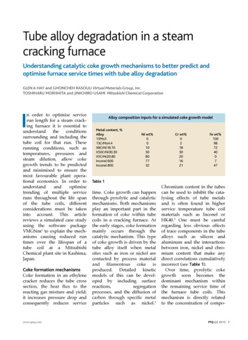
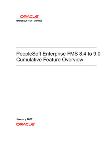
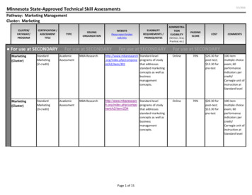
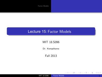
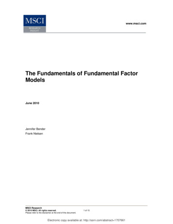
USE OF CUMULATIVE DEGRADATION FACTOR PREDICTION AND LIFE TEST RESULT OFTHE THRUSTER GIMBAL ASSEMBLY ACTUATOR FOR THE DAWN FLIGHT PROJECTC. John LoNorthrop Grumman Aerospace SystemsRedondo Beach, California 90278John R. Brophy, M. Andy Etters, and Rajeshuni RameshamJet Propulsion LaboratoryPasadena, California 91109William R. Jones, Jr.Sest, Inc.Middleburg Heights, Ohio 44130Mark J. JansenUniversity of ToledoToledo, Ohio 43606Each Ion Engine/TGA is single string with noredundancy. System redundancy is provided byrequiring two out of the three Ion Engine/TGA tooperate for the full mission duration. The TGA is ahexapod design with two articulating crank-armactuators, changing the effective length of the legs andproviding pointing control for the Ion Engine. Adrawing and photo of the TGA hexapod gimbal [2] isshown in Figures 3 and 4.ABSTRACTDawn [1]-[3] is the ninth project in NASA’s DiscoveryProgram. The Dawn spacecraft is being developed toenable the scientific investigation of the two heaviestmain-belt asteroids, Vesta and Ceres. Dawn is the firstmission to orbit two extraterrestrial bodies, and thefirst to orbit a main-belt asteroid. The mission isenabled by the onboard Ion Propulsion System (IPS) toprovide the post-launch delta-V [1]. The three IonEngines of the IPS are mounted on Thruster GimbalAssembly (TGA) [2], with only one engine operatingat a time for this 10-year mission. The three TGAsweigh 14.6 kg [1].Figure 3 – Dawn Hexapod GimbalFigure 1 – Dawn Flight System ConfigurationFigure 4 – TGA during assembly (May 2006)The input to the crank arm actuator is a vendorprovided (Starsys Inc., Louisville, CO, USA)gearmotor, with a new two phase 45 stepper motordesign driving a two stage (4.333 x 4.333) planetarygearbox. The gearbox has Mars Exploration Rover(MER) heritage and was used in the wheel steeringactuators. The gearmotor output then drives a standardFigure 2 – IPS Thrusters ConfigurationNASA/CR—2009-2156811
Harmonic Drive System (HDS) (Type 17 harmonicdrive with a 100:1 gear reduction) using 52100 bearingmaterials in the wave generator bearing. The outputangle is 0.024 degree per step. The output stage isdesigned and built by JPL. The harmonic drive outputis then connected to the crank-arm by a duplex 440CStainless Steel (SS) pair bearing (Figure 5).Figure 6 – The Spiral Orbit TribometerCustom Vascomax C-300 test and guide plates werefabricated for the SOT, and a 440C SS 1/2 inch (12.7mm) diameter ball was used as Vascomax C-300 ballswere not available. The test plates were run withBraycote 601EF and 602EF greases, Brayco 815Zand Pennzane oils with the 440C SS test balls. TheseSOT tests are then compared with 440C SS testplate/ball used as reference. The purpose of this test isto investigate whether the Vascomax C-300 materialhas any accelerating effect on the lubricantconsumption rate as seen by the 17-4 PH SS withPennzane in the Microwave Limb Sounder AntennaActuator Assembly (AAA) [4]. The SOT tests wererun in ultrahigh vacuum ( 10-6 Pa). A normalizedlubricant lifetime was determined by dividing thenumber of ball orbits at failure (friction coefficient of0.28) by the amount of lubricant deposited on the ball.This yields a lifetime in orbits/µg of lubricant and isused to compare different combinations and twotemperatures.Figure 5 – Dawn TGA ActuatorThe TGA crank arm actuator is a new design. Thelubricant life prediction as presented at the TGACritical Design Review (CDR) in May 2004 did notprovide sufficient rationale as to why the lubricationwill survive the predicted mission life time. Once thisdeficiency was identified, the Cumulative DegradationFactor [4] (CDF) technique was implemented todetermine whether the design could meet the missionlifetime requirement before completing thegearmotor/actuator design and assembly. As a resultof this study, numerous changes, including missionduty cycle definition, motor rotor bearing preloadvalue and additional amount of lubricant applied to therotor bearings were implemented to assure missionsuccess, plus a successful life test. In addition, arevised stepper motor design, using external resistorsto stabilize the system resistance, was incorporated inthe same time period to work with the existing motorcontrol logic.1.A dedicated crank arm actuator Life Test Unit (LTU)was initially used in one of the two arms in theQualification TGA. The LTU was subjected to 6-1/2thermal cycles between 120 C to -70 C in GN2 a tqualification temperature during actuator level testing,then installed in the TGA for the qualificationvibration test to qualification level and duration (2minutes/axis). Due to a problem with the specialwelded Resistoflex fitting adaptors during vibrationtesting, and subsequent retest, the TGA was subjectedto a total of 12 minutes of vibration testing, twice thenormal duration. After vibration, the LTU wasremoved from the qualification TGA and replaced withan EM actuator for further TGA comprehensiveperformance testing (CPT). A post-vibration 1-1/2thermal cycle test was performed to verify theEXPERIMENTALA Spiral Orbit Tribometer (SOT) (Figure 6) was usedto study the lifetime of the maraging alloy steel,Vascomax C-300 gear materials used in the two-stageplanetary gearbox. No data existed prior to this studyon the new Vascomax C-300 material when used in amechanical moving assembly (MMA) for space flight.The SOT [5] measures lubricant consumption in theboundary lubrication regime to provide a comparativetribological consumption rate quickly with differentmaterial combinations, contact stresses andtemperatures.NASA/CR—2009-2156812
performance of the LTU. This testing also consisted ofMotor Threshold Voltage (MTV) and running torquetesting at temperature and ambient. After successfullycompleting these tests, the LTU was setup in a bell jarvacuum chamber and programmed for a long durationlife test, using precise power control to bring thethermally isolated LTU actuator to between 55 C to 89.5 C running temperature in a set profile byheating the winding and the two external resistors.For a five-year lifetime, at a 10% duty cycle, the motorbearings will experience approximately 100 millionrevolutions. This is based on 4,380 hours of operationat 6.25 revolutions/sec.The bearings are small(0.375” OD), 440C SS, Conrad deep groove bearingswith eight 1/16” diameter balls. The ball-raceconformity is 56% and the free contact angle is 15.6degrees. The final selected preload was 1.00 0.25 lbf.Assuming a maximum preload of 1.25 lbf, the meanHertzian stress is 113 ksi. For the eight ballcomplement, one shaft revolution will yield four ballpasses. Therefore, 100 million revolutions yields 400million ball passes. Multiplying this value with themean Hertzian stress yields a CDF of approximately4.5 x 1013 ball passes-psi. For comparison, measuredCDF values for several bearing life tests appear inTable 1.Periodic measurements using Lab View softwaremeasures the MTV automatically to monitor changesto the internal running friction, giving an indication asto the state of the lubricant inside the LTU. The LTUlife test was completed in May 2006, and the LTUdisassembled at JPL. The gearmotor was returned tothe vendor for further disassembly.2.Table 1, Measured Cumulative Degradation FactorRESULTS2.1 Cumulative Degradation Factor PredictionThe Cumulative Degradation Factor (CDF) analysisinitially indicated “Very Low Probability of Success”as designed at the CDR. The proposed lubricants forthe DAWN TGA are all based on Brayco 815Z, linearperfluoropolyether oil. This oil and its greasevariations have been the lubricants of choice for spacemechanisms for many years. The gears and gearboxwas to be lubricated with Braycote 602EF grease.Braycote 601EF grease and Brayco 815Z oil were tobe used in the motor, motor bearings, and output shaftbearings. Both greases contain a PTFE thickener andBraycote 601EF also contains a bentonite claycorrosion inhibitor and sodium nitrite rust inhibitor.The Braycote 602EF only contains MoS2, a solidlubricant. . The TGA ball bearings are made of 440Cstainless steel and the gears are made of Vascomax C300, maraging steel containing Ni, Co, and Mo.Only measured CDF by testing in vacuum were usedfor comparison as even a small amount of moisturefrom GN2 or LN2 can greatly reduce the lubricantconsumption rate [7].This prediction was then used as the tool to convincethe Dawn project to accept the spacecraft vendor’s(Orbital Science Corp., Dulles, VA) mission duty cycleestimate of 1%. With this realistic value of 1%mission duty cycle, and in combination with the lowestpractical rotor bearing preload, the prediction using theCDF technique changes to “High Probability ofSuccess” for meeting the updated mission requirementwith a revised CDF of 4.5 x 10¹² bp-psi. This revisedCDF is in the midrange of Lockheed Martin’s failurerange of 2.2 to 8.7 x 10¹² bp-psi based on bearing lifetests [6].After examining the relative number of stress cycles ofall TGA bearings, it was determined the motorbearings were at greatest risk because they undergo themost cycles. Planet bearings see reduced cyclesbecause of the various gear ratios in the TGA.Therefore, calculations are based only on the motorbearings.Although the CDF for bearing tests with Pennzane oilformulations is an order of magnitude greater than forBrayco 815Z, Pennzane was not chosen for the MMAsince the unit would be operating at elevatedtemperature. The vapor pressures of Pennzaneformulations are about two orders of magnitude greaterthan Brayco 815Z at temperatures approaching 90 C.The actual consumption and evaporation rates shouldbe measured with the SOT and in actual bearing lifetests at these higher temperatures. The operatingWhen the 10% mission duty cycle, proposed by JPL,was used in the calculation of the CDF, it clearlyindicated that the lubricant in the motor bearing wouldnot survive. With full cooperation from the gearmotorvendor, a different design was implemented to lowerthe motor rotor bearing preload, to 25% of the initialvalue at 1.0 0.25 lbf. However, this redesign CDFcalculation still yielded the same failure prediction.NASA/CR—2009-2156813
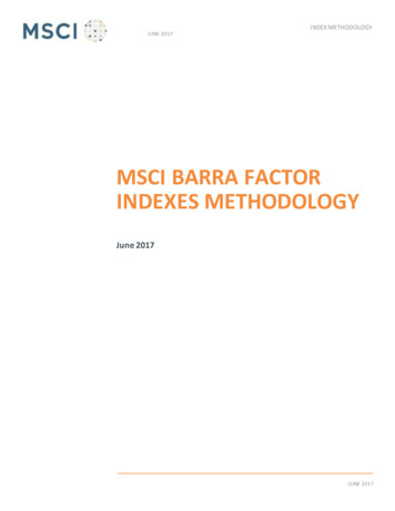
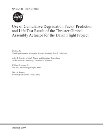
temperature for the Dawn TGA, while the Ion Engineis running, is predicted to be between 55 to 89.5 C,and is beyond life test and on-orbit experience forPennzane formulations. It was felt that the risk ofusing Pennzane at this temperature is high without athorough investigation and test program.2.4 EM 1 ConfigurationThe first EM had the original 4 lbf preload and thestandard (larger -1) gear with the revised steppermotor. The rationale is that the first path finding EMshould be built as quickly as possible with existinghardware. This EM was used in the thermal dynochamber setup, resulting in the discovery of gearbinding at temperatures below –55 C.2.2 Vascomax C-300 Consumption RateThe SOT results (Figure 7) indicated Vascomax C-300did not have an accelerated lubricant consumption ratewith Braycote 601EF grease. However, the data didindicate a reduced lifetime on both Vascomax and440C SS with 602EF when compared to 601EF. Thegearmotor vendor was quickly directed to change fromthe 602EF lubricant (used on MER) to 601EF tomaximize life of the gears used on Dawn. Also, allMMA processes for the Dawn TGA at JPL use the601EF grease with Braycote 600 used for greaseplating.2.5 EM2 ConfigurationThe second EM, EM2, was initially intended to be theLTU. The rotor bearing preload was lowered to 2 lbfeasily by using different thickness shim washers. EM2was assembled with the smaller -2 gears with lighthand lapping. The CDF with the 2 lbf was in anacceptable range, but on the high side of the failurerange. EM2, with 2.0 lbf and -2 gears, was delivered toJPL and went through the full qualification thermaldyno test profile for 6-1/2 thermal cycles whilemodifications to the rotor bearing preload was beingengineered.This EM2 produced acceptableperformance, but with more reduction in output torqueat temperatures below –55 C, indicating high internalfriction.2.6 LTU ConfigurationSubsequently, the target rotor bearing preload waslowered even further, to 1.0 0.25 lbf for the third unitbeing built. This unit, the LTU, used a differentpreload bearing cup design, with each wave springmeasured and the cup match machine to bring thepreload to the design range. The rotor bearings aregrease plated and four additional drops of Brayco 815Zoil added to every other ball for each rotor bearing.The gearbox used the smaller -2 gears with very lightlapping to a newly defined “end play” target range forthe gearmotor output. After grease plating the gearsand the bearings in the planetary gearbox, additionalgrease strips with Braycote 601EF were applied on theinside of the gearbox housing. After bake out, theLTU was brought down to –108 C cold survivaltemperature, then 6-1/2 thermal cycles between –70 Cto 120 C, with dyno runs at the first and last thermalcycle. Below (Figure 8) is the thermal dyno test resultfor the LTU in April 2005:Figure 7 – Vascomax C-300 SOT Test( 10 -68 Pa, 40 RPM, 1.5 GPa mean Hertzian Stress)2.3 Modifications to the Stepper MotorThe initial gearmotor specification omits the allowablemaximum torque and the first generation stepper motorwas designed to the maximum capability of the twostage planetary gearbox. This excessive torque willdamage the harmonic drive, producing a calculatedtorque of more than 1,500 in-lbs. The gearmotorspecification was then clarified with clear definition ofthe winding configuration (shorting of un-poweredwinding), two missions specified fixed pulse width at15 and 20 ms, and allowing the addition of externalresistors to stabilize motor current (constant voltagedriver) over the wide temperature range. The revisedmotor also incorporated the reduced preload afterdelivery of the first Engineering Model (EM).NASA/CR—2009-2156814
Figure 8 – LTU Pre-Vibe Thermal Dyno Test, 50 ppsThe pulse width is commandable from the ground tofull pulse width (20 ms) if needed, with an increase ofapproximately 30 to 40 in-lb of output torque from the15 ms value.against a titanium gearmotor output adaptor hub.Titanium could, and in this case did, acceleratedegradation of the Braycote lubricant. Futuregearmotors should fabricate this output adaptor hubwith 440C SS materials to prevent this defect so thatthe retainer, with the Braycote lubricant, will slide on aknown material that will not accelerate break down ofthe lubricant.Post-Vibe thermal dyno test of the LTU in July 2005produced similar torque output, MTV and nomovement due to vibration by measuring the numberof steps to actuate the microswitches at the hardstopposition.2.8 HD Wave Generator Bearing Materials2.7 HD Wave Generator Bearing SeparatorOrientationThe off-the-shelf HDS harmonic drive uses 52100bearings. Much effort was spent on run in anddifferent techniques to prevent the bearing fromrusting after precision cleaning. Future gearmotordesigns should specify 440C SS bearings to simplyprocessing. The additional lead time using the 440CSS bearing is well worth the wait.An EM TGA was built in the summer of 2004, withflight configuration titanium struts, actuator bracket,and all flight like hardware as the vibration test fixtureto qualify the three flight ion engines. Instead of agearmotor, a simple mass model took its place, withmanual crank to drive the input to the wave generatorof the harmonic drive. The separator was installed onthe “closed” side of the flex spline of the harmonicdrive. In order to keep the separator from popping offwhen load was applied, a set of custom shims and alarge 400 series SS wash
E-mail your question via the Internet to help@ sti.nasa.gov Fax your question to the NASA STI Help Desk at 443–757–5803 Telephone the NASA STI Help Desk at 443–757–5802 Write to: NASA Center for AeroSpace Info