Transcription
Design ManualDesigners & InstallersEngineers & ArchitectsManufactured by: BW Vista RailingsTel: 1-800-667-8247 Fax: 604-467-1197www.VistaRailings.com6th Edition
Vista Design Manual – CANADIAN./2TABLE OF CONTENTSTABLE OF CONTENTS . . 2LIST OF FIGURES. . 3LIST OF TABLES. . . 31.0INTRODUCTION . . 42.0GENERAL DESIGN . 42.1DESIGN CRITERIA . 52.1.1 Loadings . 52.1.2 Factors Of Safety . 52.2MATERIALS AND PROPERTIES . 62.2.1 Mechanical Properties Of Aluminum Alloys And Elements . 62.2.2 Physical Properties Of Guardrail Elements . 62.3ELEMENT AND SYSTEM LOAD CAPACITIES. 92.4LOAD DISTRIBUTION . 92.5ANCHORAGE . 92.6WEAKNESS IN WELDED ALUMINUM . 182.7DESIGN PROCEDURES . 182.7.1 Top Rail Design . 182.7.2 Post Design . 193.0DESIGN TABLES. . 193.1WIND LOADING . 193.2GUARDRAIL HEIGHT VARIATIONS . 203.3GUARDRAIL SYSTEMS WITH ALUMINUM PICKET INFILL . 203.4GUARDRAIL SYSTEMS WITH GLASS PANEL INFILL . 203.5FASCIA MOUNTED POSTS . 214.0LETTER OF CONFORMANCE . 22ALCO RAILINGSVENTURES INC.BW VISTALTD.
Vista Design Manual – CANADIAN./3LIST OF FIGURESFIGURE 1:FIGURE 2:FIGURE 3:FIGURE 4:FIGURE 4A:FIGURE 4A‐A:FIGURE 4B:FIGURE 4B‐A:FIGURE 4C:FIGURE 4D:FIGURE 4E:FIGURE 4F:FIGURE4G:FIGURE 4H:FIGURE 4H‐A:FIGURE 4I:FIGURE 4I‐A:FIGURE 4J:FIGURE 4K:FIGURE 4L:FIGURE 4M:FIGURE 4N:FIGURE 4O:FIGURE 4P:FIGURE 4P‐A:FIGURE 4Q:MAIN ELEMENTS OF GUARDRAIL SYSTEMS . 4TYPICAL CROSS‐SECTIONS OF COMMON GUARDRAIL ELEMENTS . 8ACCEPTABLE GUARDRAIL MOUNTING CONFIGURATIONS . 12GUARDRAIL CONFIGURATIONS . 2342" HIGH ALLOWABLE CONFIGURATIONS TYPE 1A . 2442" HIGH ALLOWABLE CONFIGURATIONS TYPE 1A ALTERNATE . 2542" HIGH ALLOWABLE CONFIGURATIONS TYPE 1B . 2642" HIGH ALLOWABLE CONFIGURATIONS TYPE 1B ALTERNATE . 2742" HIGH ALLOWABLE CONFIGURATIONS TYPE 1C . 2842" HIGH ALLOWABLE CONFIGURATIONS TYPE 1D . 2942" HIGH ALLOWABLE CONFIGURATIONS TYPE 1E . 3042" HIGH ALLOWABLE CONFIGURATIONS TYPE 2A . 3142" HIGH ALLOWABLE CONFIGURATIONS TYPE 2B . 3242" HIGH ALLOWABLE CONFIGURATIONS TYPE 3A . 3342" HIGH ALLOWABLE CONFIGURATIONS TYPE 3A ALTERNATE . 3442" HIGH ALLOWABLE CONFIGURATIONS TYPE 3B . 3542" HIGH ALLOWABLE CONFIGURATIONS TYPE 3B ALTERNATE . 3642" HIGH ALLOWABLE CONFIGURATIONS TYPE 3C . 3742" HIGH ALLOWABLE CONFIGURATIONS TYPE 3D . 3842" HIGH ALLOWABLE CONFIGURATIONS TYPE 4A . 3942" HIGH ALLOWABLE CONFIGURATIONS TYPE 4B . 4042" HIGH ALLOWABLE CONFIGURATIONS TYPE 5A . 4142" HIGH ALLOWABLE CONFIGURATIONS TYPE 5B . 4242" HIGH ALLOWABLE CONFIGURATIONS TYPE 6A . 4342" HIGH ALLOWABLE CONFIGURATIONS TYPE 6A ALTERNATE . 4442" HIGH ALLOWABLE CONFIGURATIONS TYPE 6B . 45LIST OF TABLESTABLE 1:TABLE 2:TABLE 3:MECHANICAL PROPERTIES OF ALUMINUM ALLOYS AND ELEMENTS . 6PHYSICAL PROPERTIES OF COMMON ELEMENTS . TESTINGRESULTS. 10ALCO VENTURESINC.LTD.BW VISTARAILINGS
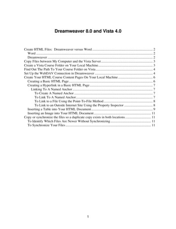
Vista Design Manual – CANADIAN./41.0INTRODUCTIONPermanent guardrail systems are required near or at the open sides of elevated walking/viewing surfaces for thepurpose of minimizing the potential of an accidental fall to a lower level.Aluminum guardrail assemblies are commonly comprised of straight sections of top rail elevated and supportedabove a floor by uniformly spaced posts. The posts are anchored to the floor system by means of anchor screws orbolts. A bottom channel runs between support posts just above the floor system. The vertical space between theposts, the bottom channel and top rail is infilled with either glass panels or aluminum pickets. Figure 1 belowillustrates the main elements of a glass panel and aluminum picket guardrail system.FIGURE 1: MAIN ELEMENTS OF GUARDRAIL SYSTEMS2.0GENERAL DESIGNThis manual has been compiled to provide relevant structural information which will enable designers, installers,architects, and engineers to select safe and code‐conforming guardrail designs using Alco Ventures Inc. products.The major considerations for the structural design of guardrails are:1.Structural design criteria as established by governing building codes, bodies and authorities or byspecial established project design requirements,2.Mechanical properties of material used in manufacture of guardrail elements,3.Physical properties of guardrail elements,4.Load capacities of guardrail elements and component systems,5.Load distribution characteristics of various guardrail elements and systems, and6.Proper anchorage of support elements to surrounding supporting structures.VENTURESINC. LTD.BW ALCOVISTARAILINGS
Vista Design Manual – CANADIAN./52.1DESIGN CRITERIA2.1.1LoadingsStructural design loading requirements for guardrails are specified by governing building codes and bodies,local ordinances, project specifications and/or regulatory authorities. Usually a uniformly distributed loadand/or concentrated load applied to the top rail is specified. The loading requirements of The NationalBuilding Code of Canada (NBCC) 2005 for guardrails are provided under clauses 4.1.5.15. Loads on Guards1) to 5). The clauses are repeated below:4.1.5.15.Loads on Guards1)The minimum specified horizontal load applied inward or outward at the top of every requiredguard shall bea)3.0 kN/m (205.6 plf) for means of egress in grandstands, stadia, bleachers and arenas,b)a concentrated load of 1.0 kN (225 lbs.) applied at any point for access ways to equipmentplatforms, contiguous stairs and similar areas where the gathering of many people isimprobable andc)0.75 kN/m (51.4 plf) or a concentrated load of 1.0 kN (225 lbs.) applied at any point,whichever governs, for locations other than those described in Clauses (a) and (b).2)Individual elements within the guard, including solid panels and pickets, shall be designed for a loadof kN (112.5 lbs.) applied over an area of 100 mm (4") by 100 mm (4") located at any point in theelement or elements so as to produce the most critical effect.3)The loads required in Sentence (2) need not be considered to act simultaneously with the loadsprovided for in Sentences (1) and (4).4)The minimum specified load applied vertically at the top of every required guard shall be 1.5 kN/m(102.8 plf) and need not be considered to act simultaneously with the horizontal load provided forin Sentence (1).5)For loads on handrails, refer to Sentence 3.4.6.4.(9).2.1.2Factors of SafetyFactors of safety for a guardrail system can be a somewhat subjective decision to be determined by thedesigner or certifying professional. Factors of safety are generally related to a mode of failure. Ductilefailure, such as stable (no buckling) yielding of a metal element, is usually assigned a lower factor of safetythan is brittle failure, such as screw fracture or anchor bolt pullout. Part 4 of the NBCC 2005 specifies a loadfactor of 1.5 to be applied to live loads. Since it is unlikely that the failure of any one component will causethe entire system to fail, a factor of safety of 1.5 for element and system design would seem appropriate. Ahigher or lower factor of safety may be appropriate depending upon the type of application and otherconsiderations made by the certifying professional. For instance, a higher factor of safety may be moreappropriate for glass infill panels since their failure is of a brittle nature. The guardrail configurations/designtables provided at the end of this manual have been developed using a minimum overall system factor ofsafety of 1.5.BW VISTARAILINGSALCO VENTURESINC. LTD.
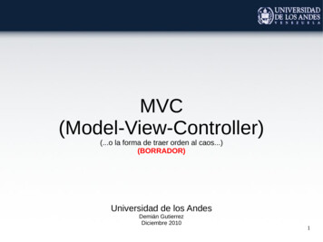
Vista Design Manual – CANADIAN./62.2MATERIALS AND PROPERTIES2.2.1Mechanical Properties Of Aluminum Alloys And ElementsMechanical properties of aluminum alloys used in Alco Ventures Inc. Guardrail Systems are provided inCAN3‐S157‐M83 Strength Design in Aluminum and are listed in Table 1 below. Properties vary with thecomposition and temper of the material and also, to some degree, with the profile and the direction ofstress.Table 1: MECHANICAL PROPERTIES OF ALUMINUM ALLOYS AND PRODUCTSAlloy & productsNOT WELDEDTensileTensile yieldultimate FuFyCompressiveyield FyWELDEDTensileTensile yieldultimate FwuFwyElasticmodulus EExtrusions anddrawn tube6063‐T5150 MPa (21.8ksi)110 MPa (16.0ksi)70 000 MPa(10 000 ksi)6063‐T54230 MPa (33.4ksi)205 MPa (29.8ksi)205 MPa (29.8ksi)120 MPa (17.4ksi)70 MPa (10.2ksi)70 000 MPa(10 000 ksi)6063‐T6205 MPa (29.8ksi)170 MPa(24.7 ksi)170 MPa(24.7 ksi)120 MPa(17.4 ksi)70 MPa(10.2 ksi)70 000 MPa(10 000 ksi)6061‐T6260 MPa (37.7ksi)240 MPa (34.8ksi)240 MPa (34.8ksi)170 MPa (24.7ksi)110 MPa (16.0ksi)70 000 MPa(10 000 ksi)6005A‐T61262 MPa (38.0ksi)241 MPa (35.0ksi)241 MPa (35.0ksi)Extrusions sheet,plate, and drawntube2.2.270 000 MPa(10 000 ksi)Physical Properties Of Guardrail ElementsPhysical properties of sections of commonly used elements in Alco's Guardrail Systems are given in Table 2.Typical cross‐sections of these elements are provided in Figure 2. Additional elements are show in Alco'sDealer Catalogue.ALCO VENTURESINC. LTD.BW VISTARAILINGS
Vista Design Manual – CANADIAN./7TABLE 2: PHYSICAL PROPERTIES OF COMMON ELEMENTSELEMENTSTOP RAILS57.2 mm (2 ¼”) round top railfor glass panel infillALLOYlxx106MM44(IN )AREA2MM2(IN )Sxx103mm43(in )lyy106mm44(in )Syy103mm43(in .861(.358)57.2 mm (2 ¼”) square top railfor glass panel .523)7.439(.454)57.2 mm (2 ¼”) round top railfor picket .397)5.654(.345)57.2 mm (2 ¼”) square top railfor picket .154).105(.251)3.966(.242)Outside round top (.268).164(.394)5.443(.332)Outside square top 63.5 mm (2 ½”) square post6005A‐T61*****50.8 mm (2”) square post6005A‐T61*****38.1 mm (1 ½”) square post6005A‐T61*****MISCELLANEOUS31.8 mm (1 ¼”) schedule 40handrail 42(.021).003(.007).342(.021)various plates6061‐T6TOP RAIL SLEEVES/CORNERSInside round top railsleeve/cornerBOTTOM RAILSBottom rail for glass panelsystemBottom rail for picket panelsystemLegendI – moment of inertiaS – section modulus*‐ element data exclusive property of Alco Ventures Inc. Use test results from Table 3 for design purposesVENTURESINC. LTD.BW ALCOVISTARAILINGS
Vista Design Manual – CANADIAN./8TOP RAILSTOP RAIL SLEEVES/CORNERSBOTTOM RAILSPOSTSFIGURE 2: TYPICAL CROSS‐SECTIONS OF COMMON GUARDRAIL ELEMENTSVENTURESINC. LTD.BW ALCOVISTARAILINGS
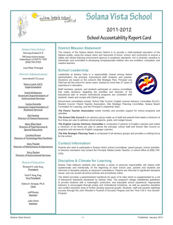
Vista Design Manual – CANADIAN./92.3ELEMENT AND SYSTEM LOAD CAPACITIESCanadian Standards Association Document CAN3‐S157‐M83 Strength Design in Alumium can be used indetermining individual component capacities using conventional engineering design procedures. This method issomewhat conservative and limiting since it does not give consideration to the varying interactions of the elementsin determining the load carrying capacity of the guardrail system. Complicated analysis procedures are necessary toachieve information for a more efficient design.Alternatively, clause 1.4.1 of the aforementioned standard states, "In lieu of design calculations, the adequacy of astructural assembly may be proved by tests." Alco Ventures Inc. has conducted an extensive testing program usingthe services of Intertek Testing Services Na Ltd./Warnock Hershey, some of the results of which are provided inTable 3. Reports of the tests are available upon request. Since test results generally reflect more accurately theactual load carrying capacity of elements and systems, Alco Ventures Inc. recommends the use of test results,where possible, in determining acceptable guardrail designs.2.4LOAD DISTRIBUTIONProper determination of load distribution is a necessary step in the efficient design of guardrail systems. Loaddistribution is affected by numerous factors, including but not limited to, the stiffness of the top rail relative to thestiffness of the posts, the continuity of the top rail, the lenth of each straight segment, the number of spans in asegment, the type of panel infill, and the end support conditions. Accurately determining the load distributioncharacteristics of a guardrail system requires a sophisticated approach. Alco Ventures Inc. has developedspecialized computer modelling to determine the load distribution for its various systems and has performedextensive testing to verify the results.Analysis and design of unique configurations requires specialized engineering which can be provided by AlcoVentures Inc. Use of this information in combination with test results is essential for the efficient design of safeguardrail systems.2.5ANCHORAGEProper anchorage of guardrail posts and rails to a sound and structurally adequate supporting structure is essentialfor a guardrail system. These elements must be as secure and rigid as possible. A structurally adequate supportingstructure is as important as the anchorage elements themselves. One without the other compromises the loadcarrying capacity and performance of the guardrail system. Building designers and general contractors must bemade aware of their responsibility to provide for proper support conditions since this is beyond the normal scopeand control of the guardrail system designer or installer.The anchorage and supporting structure for each post must be designed to carry the applied loads and theirassociated overturning moments at the post base. These loads comprise of shear, tension and compression forceswhich must be resisted. Figure 3 indicates some common and approved post base connections.The anchorage and supporting structure of each top (and bottom) rail to base building components (wall, column,etc.) connection must be designed to carry the applied loads transferred from the top and bottom rail. Theconnection is assumed to provide pivot support with no flexural resistance. Shear loads and, depending upon thesystem configuration, pullout loads must be resisted. Figure 3 indicates some common and approved top andbottom rail to base building component connections.VENTURESINC. LTD.BW ALCOVISTARAILINGS
Vista Design Manual – CANADIAN./10TABLETABLE3: BWRAILINGSLTD.TESTINGRESULTS3: VISTAALCO VENTURESINC.TESTINGRESULTSElement/Component SystemAverage Ultimate Load AppliedMode of FailureTOP RAILS57.2 mm (2 ¼”)3879 N (872 lbs.) total applied at 1/3 spanround top rail for glass panel infillpoints57.2 mm (2 ¼”) square top rail for glass4657 N (1047 lbs.) total load applied at 1/3panel infillspan points57.2 mm (2 ¼”) round top rail for picket infill4688 N (1054 lbs.) total load applied at 1/3Buckling @ load pointBuckling @ supportBuckling @ load pointspan points57.2 mm (2 ¼”) square top rail for picket5609 N (1261 lbs.) total load applied at 1/3infillspan pointsBuckling @ supportTOP RAILS WITH SLEEVES57.2 mm (2 ¼”) round top rail with inside3966 N (892 lbs.) total load applied at 1/3Fastener tearing inner sleeve flangesleeve for picket infillspan points57.2 mm (2 ¼”) square top rail with outside4763 N (1071 lbs.) total load applied at 1/3Bending/deformation of rail ends at midspansleeve for picket infillspan pointsconnector90 round external corner4350 N (978 lbs.) in tension and shearBottom inner weld of sleeve mitre tore open90 square external corner2980 N (670 lbs.) in tension and shearBottom inner weld of sleeve mitre tore open135 round external corner5308 N (1193 lbs.)Bottom inner weld of sleeve mitre tore open135 square external corner4263 N (958 lbs)Bottom inner weld of sleeve mitre tore open63.5 mm (2 ½”) square post anchored to1837 N (413 lbs.) horizontal load @ 1067Bottom screws pulled through base platesteel framemm (42”) height50.8 mm (2”) square post anchored to steel1370 N (308 lbs.) horizontal load @ 1067framemm (42”) height50.8 mm (2”) square post fascia mounted to1815 N (408 lbs.) horizontal load @ 1067steel frame (42”) heightmm38.1 mm (1 ½”) square post anchored to876 N (197 lbs.) horizontal load @ 1067 mmsteel frame(42”) height38.1 mm (1 ½”) square post fascia mounted946 N (213 lbs.) horizontal load @ 1067 mmPost wall buckling above upper support38.1 mm (1 ½”) square post with inside1419 N (319 lbs.) horizontal load @ 1067Restraining picket brace broke baseplatepicket brace anchored to steel framemm (42”) heightweldCORNERSPOSTSBottom screws pulled through base platePost wall buckling above upper supportPost wall buckling above upper supportto steel frame (42”) heightVENTURESINC. LTD.BW ALCOVISTARAILINGS
Vista Design Manual – CANADIAN./113: VISTAALCO VENTURESINC.TESTINGRESULTSCONTINUEDTABLETABLE3: nent SystemAverage Ultimate Load AppliedMode of FailureMISCELLANEOUS31.8 mm (1 ¼”) schedule 40 handrail91529 N (344 lbs.) total load applied at 1/3Uniform bending failurespan pointsTop rail end clip6437 N (1447 lbs.) in shearForward screw top laterally out of chaseBottom channel end clip7915 N (1779 lbs.) in shearForward screw top laterally out of chaseHandrail bracket1130 N (254 lbs.)Bracket yielded522 N (117 lbs.) at midspan edgeFracture1162 N (261 lbs.) at midspan edgeFracture5 mm (.197”) tempered glass panel 914.437.8 kPa (79 psf) distributed load over entireGlass panel slips out of bottom railmm (36”) x 1219.2 mm (48”)panelGLASS PANELS5 mm (.197”) tempered glass panel 914.4mm (36”) x 304.8 mm (12”)5 mm (.197”) tempered glass panel 914.4mm (36”) x 1219.2 mm (48”)PICKET15.9 mm (5/8”) picket1140 N (256 lbs.) at midspanWeld failure at end connection15.9 mm (5/8”) picket panel 1118 mm (44”)33.3 kPa (696 psf) distributed loading atWeld failure at end connectionx 972 mm (38 ¼”)midspan over 350 mm (12”) x 350 mm (12”)areaFASTENERS#14 x 2 ½” screw secured to solid fir lumber9359 N (2104 lbs) withdrawalScrew pulled out of wood#14 x 2 ½” screw secured to solid spruce6632 N (1491 lbs.) withdrawalScrew pulled out of wood21445 N (4821 lbs.) withdrawalRestraining bolt tore through the aluminumlumber#14 x 2” screw in post screw chasepost#8 x 1 ½” screw in top rail sleeveNOTES:1.2.3.4.4982 N (1120 lbs.) withdrawalScrew neck elongated and broke below headTests conducted by Intertek Testing Services Na Ltd./Warnock Hersey – reports available upon request.Test procedures in general conformance with ASTM Standard Specification E 985‐87 for Permanent Metal RailingSystems and Rails for Buildings and ASTM Standard Test Methods E 935‐85a for Performance of Permanent MetalRailing Systems and Rails for Buildings.Testing reviewed by Lang Structural Engineering Inc.Design load for elements as specified by CSA CAN3‐S157‐M83 Strength Design in Aluminum for live loading isrecommended to be the test load/1.5 (ultimate load capacity/1.5).ALCO VENTURESINC.LTD.BW VISTARAILINGS
9474-199A ST.LANGLEY, B.C.CANADA V1M 2X7PH: (800)-667-8247FAX: (604)-467-1197ALCO VENTURESINC.LTD.BW VISTARAILINGS
9474-199A ST.LANGLEY, B.C.CANADA V1M 2X7PH: (800)-667-8247FAX: (604)-467-1197BW VISTA RAILINGS LTD.
9474-199A ST.LANGLEY, B.C.CANADA V1M 2X7PH: (800)-667-8247FAX: (604)-467-1197ALCO VENTURESINC.LTD.BW VISTARAILINGS
9474-199A ST.LANGLEY, B.C.CANADA V1M 2X7PH: (800)-667-8247FAX: (604)-467-1197BW VISTA RAILINGS LTD.
9474-199A ST.LANGLEY, B.C.CANADA V1M 2X7PH: (800)-667-8247FAX: (604)-467-1197BW VISTA RAILINGS LTD.
9474-199A ST.LANGLEY, B.C.CANADA V1M 2X7PH: (800)-667-8247FAX: (604)-467-1197BW VISTA RAILINGS LTD.
Vista Design Manual – CANADIAN./18To assist in design, the maximum service pull‐out loads to be resisted by each anchor is summarized below for eachtype of post and anchorage configuration:Post38.1mm(1 ½”)top mountusing BWbase plates3505 N(788 lbs.)fascia mount to woodusing double BWfascia brackets2985 N (671 lbs.)5 ½” vertical spacingbetween anchors*50.8mm(2”)5480 N(1232 lbs.)5720 N (1286 lbs)5 ½” vertical spacingbetween anchors *63.5mm(2 ½”)7348 N(1652 lbs.)Anchorage Configurationfascia mount tofascia mount to woodconcrete using double using single BWBW fascia bracketsfascia bracket3830 N (861 lbs.)2998 N (674 lbs.)3” vertical spacing5” vertical spacingbetween anchors *between outeranchors*6432 N (1446 lbs.)4462 N (1003 lbs.)3 ¾” vertical spacing5” vertical spacingbetween anchors*between outeranchors*3937 N (885 lbs.)5” vertical spacingbetween outeranchors*fascia mount toconcrete using singleBW fascia bracket2869 N (645 lbs.)5” vertical spacingbetween outeranchors*5636 N (1267 lbs.)5” vertical spacingbetween outeranchors*5707 N (1283 lbs.)5” vertical spacingbetween outeranchors**As per Figure 32.6WEAKNESS IN WELDED ALUMINUMA review of the mechanical properties of aluminum alloys and elements in Table 1 indicates that tensile strength issignificantly reduced in aluminum when it is welded. This has a significant impact on the strength capacity ofaluminum guardrail components, connections and systems. At the bottom connection of posts to base plates, theconnection and post capacity is substantially less in welded configurations compared to those using Vistamechanical fastening. Tests conducted by Intertek Testing Services Na Ltd./Warnock Hershey indicate that 38.1mm(1 ½”) posts with welded base plates fail at loads an average of 35% lower than identical posts with Vistamechanical base plate connections. Tests conducted by Intertek Testing Services Na Ltd./Warnock Hershey of a2 ¼” aluminum post of top deck mount configuration (an actual competitor of Vista’s) that uses a welded base platefailed at loads an average of 30% lower than the Vista 2” post. A copy of the report can be provided upon request.For these reasons, welded post base connections are generally not recommended.2.7DESIGN PROCEDURES2.7.1Top Rail DesignTop rail design normally involves using conventional engineering design procedures in determining andcomparing section resisting moment capacities to resultant bending moments from applied loads.Connections between posts and rails are assumed to provide no flexural restraint. The bending moments intop rails are affected by the number and length of spans between posts in a straight run. Computer analysisof guardrail systems most accurately determines bending moments in top rails. The top rail momentcapacity calculated using the section modulus (S) and material yield strength (Fy) (or alternatively fromanalysis of test results) must exceed the resultant bending moment from the applied loads.BW VISTA RAILINGS LTD.
Vista Design Manual – CANADIAN./192.7.2Post DesignPosts in railing systems behave somewhat as vertical cantilevered beams in resisting horizontal loadsapplied to the top rail. Bending moments caused by horizontal loads normally control allowable postspacing and design. The first step in post design is determining the actual horizontal load that each postwould be expected to carry. Horizontal load distribution from the top rail to each post is affected by anumber of factors including the relative stiffness of the post and top rail, the length of each straightsegment, the number of spans in the railing, and the end support conditions.Computer modelling and analysis based on test results of guardrail systems most accurately assimilates toprail load distribution to each of the supporting posts and end conditions. The post moment capacity iscalculated using the section modulus (S) and material yield strength (Fy). This must exceed the resultantbending moment from the applied loads or the post spacing is reduced to create an acceptable condition.3.0DESIGN TABLESThe design procedures described in the previous section have been carried out for a wide range of possibleguardrail systems. The results are summarized in the tables which follow. By knowing the overall dimensions andlayout of the guardrail system under design, an acceptable configuration can be selected using the tables.The design tables are based upon the loading criteria for exterior balconies of individual residential units asspecified in clauses 4.1.5.15. 1)a) and 4.1.5.15. 2) to 4) of the NBCC 2005. The actual load conditions for theguardrail system under design must be identical to or less than those used in the development of the tables. Thetables should not be used for other applications where different loading conditions and configurations exist.3.1WIND LOADINGFor glass infill guardrail systems, the structural strength requirements imposed by design wind loading mayexceed those imposed by specified guardrail design loads. For uniform lateral specified wind pressures ofnot greater than 1.25 kPa (26 psf), guardrail design loads are the governing criteria for 1067 mm (42”) highguardrail system design. This wind loading is generally associated with low‐rise structures in most locationsbut must be verified as part of the design process. The allowable guardrail configurations indicated in figure4 are all capable of withstanding this uniform lateral specified wind pressure. For wind pressure greaterthan 1.25 kPa (26 psf), adjust the allowable post spacing using the following formula:modified postspacing allowable postspacingBW VISTA RAILINGS LTD.X1.25specified windpressure (kPa)
Vista Design Manual – CANADIAN./203.2GUARDRAIL HEIGHT VARIATIONSThe most common guardrail system height is 1067 mm (42”) high. For guardrail heights other than 1067mm (42”), adjust the allowable post spacings as indicated in the allowable guardrail configurations of figure4 using the following formula:modified postspacing allowable postspacingXallowable postspacingmultiplier(See Table below for allowable post spacing multiplier)guardrail height457 mm (18”)610 mm (24”)762 mm (30”)914 mm (36”)1067 mm (42”)1219 mm (48”)1372 mm (54”)1524 mm (60”)1676 mm (66”)1829 mm (72”)3.3allowable post spacingmultiplier for picket 40.58allowable post spacingmultiplier for glass 00.34GUARDRAIL SYSTEMS WITH ALUMINUM PICKET INFILLCorner posts for aluminum picket infill guardrail systems may be eliminated and replaced with a picketcorner provided one of the following conditions are met:3.41)the end of the return portion of the top rail is anchored to the building, or2)the return portion of the guardrail system is supported by a minimum of 2posts.GUARDRAIL SYSTEMS WITH GLASS PANEL INFILLPost spacing for guardrail systems is generally determined by the strength of the supporting posts andapplied loads. However, for guardrail systems wit
2.2.1 Mechanical Properties Of Aluminum Alloys And Elements Mechanical properties of aluminum alloys used in Alco Ventures Inc. Guardrail Systems are provided in CAN3‐S157‐M83 Strength Design in Aluminum and are listed in Table 1 below. Properties vary with the