Transcription
MicroBlaze TutorialCreating a Simple Embedded SystemandAdding Custom Peripherals UsingXilinx EDK Software ToolsRod JesmanFernando Martinez VallinaJafar SaniieEmbedded Computing and Signal Processing Laboratory – Illinois Institute of Technologyhttp://ecasp.ece.iit.edu1
INTRODUCTIONThis tutorial guides you through the process of using Xilinx Embedded Development Kit(EDK) software tools, in which this tutorial will use the Xilinx Platform Studio (XPS) tool to createa simple processor system and the process of adding a custom OPB peripheral (an 32-bit addercircuit) to that processor system by using the Import Peripheral Wizard.OBJECTIVESAfter completing this tutorial, you will be able to: Create an XPS Project by using Base System Builder (BSB) Create a simple hardware design by using Xilinx IPs available in the Embedded Design Kit Add a custom IP to your design Modify a Xilinx generated software application to access an IP peripheral Implement the design Generate and Download the bit file to verify in hardwareIn order to download the completed processor system, you must have the following hardware: Xilinx Spartan-3 Evaluation Board (3S200 FT256 –4) Xilinx Parallel -4 Cable used to program and debug the device Serial CablePROCEDUREThe purpose of the tutorial is to walk you through a complete hardware and softwareprocessor system design. In this tutorial, you will use the BSB of the XPS system to automaticallycreate a processor system and then add a custom OPB peripheral (adder circuit) to that processorsystem which will consist of the following items: MicroBlaze ProcessorLocal Memory Bus (LMB) Bus LMB BRAM controllers for BRAM BRAM BLOCK (On-chip memory)On-chip Peripheral Bus (OPB) BUS Debug Module (OPB MDM) UART (OPB UARTLITE) 2 - General Purpose Input/Output pheriphals (OPB GPIOs) Push Buttons Dip Switches Custom peripheral (32-bit adder circuit)Embedded Computing and Signal Processing Laboratory – Illinois Institute of Technologyhttp://ecasp.ece.iit.edu2
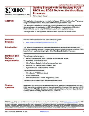
BACKGROUNDFirst, before designing the embedded processor system, some background information needsto be provided to inform you about the processor to be used and some items about the XilinxEmbedded Development Kit (EDK) software tools. The microprocessors available for use in XilinxField Programmable Gate Arrays (FPGAs) with Xilinx EDK software tools can be broken down intotwo broad categories. There are soft-core microprocessors (MicroBlaze) and the hard-coreembedded microprocessor (PowerPC). This tutorial will only focus on the soft-core MicroBlazemicroprocessor, which can be used in most of the Spartan-II, Spartan-3 and Virtex FPGA families.The hard-core embedded microprocessor mentioned is an IBM PowerPC 405 processor, which isonly available in the Virtex-II Pro and Virtex-4 FX FPGA’s. You don't have to use the PowerPC405 processors but you also can't remove them from the Virtex-II Pro and Virtex-4 FX FPGA’sbecause they are in the fabric of the chip. This section will now go into more details about theMicroBlaze microprocessor and Xilinx Embedded Development Kit (EDK) software tools.The MicroBlaze is a virtual microprocessor that is built by combining blocks of code calledcores inside a Xilinx Field Programmable Gate Array (FPGA). The beauty to this approach is thatyou only end up with as much microprocessor as you need. You can also tailor the project to yourspecific needs (i.e.: Flash, UART, General Purpose Input/Output pheriphals and etc.).The MicroBlaze processor is a 32-bit Harvard Reduced Instruction Set Computer (RISC)architecture optimized for implementation in Xilinx FPGAs with separate 32-bit instruction and databuses running at full speed to execute programs and access data from both on-chip and externalmemory at the same time. The backbone of the architecture is a single-issue, 3-stage pipeline with32 general-purpose registers (does not have any address registers like the Motorola 68000Processor), an Arithmetic Logic Unit (ALU), a shift unit, and two levels of interrupt. This basicdesign can then be configured with more advanced features to tailor to the exact needs of the targetembedded application such as: barrel shifter, divider, multiplier, single precision floating-point unit(FPU), instruction and data caches, exception handling, debug logic, Fast Simplex Link (FSL)interfaces and others. This flexibility allows the user to balance the required performance of thetarget application against the logic area cost of the soft processor. Figure 1 shows a view of aMicroBlaze system. The items in white are the backbone of the MicroBlaze architecture while theitems shaded gray are optional features available depending on the exact needs of the targetembedded application. Because MicroBlaze is a soft-core microprocessor, any optional features notused will not be implemented and will not take up any of the FPGAs resources.The MicroBlaze pipeline is a parallel pipeline, divided into three stages: Fetch, Decode, andExecute. In general, each stage takes one clock cycle to complete. Consequently, it takes threeclock cycles (ignoring delays or stalls) for the instruction to complete. Each stage is active on eachclock cycle so three instructions can be executed simultaneously, one at each of the three pipelinestages. MicroBlaze implements an Instruction Prefetch Buffer that reduces the impact of multi-cycleinstruction memory latency. While the pipeline is stalled by a multi-cycle instruction in theexecution stage the Instruction Prefetch Buffer continues to load sequential instructions. Once thepipeline resumes execution the fetch stage can load new instructions directly from the InstructionPrefetch Buffer rather than having to wait for the instruction memory access to complete. TheInstruction Prefetch Buffer is part of the backbone of the MicroBlaze architecture and is not thesame thing as the optional instruction cache.Embedded Computing and Signal Processing Laboratory – Illinois Institute of Technologyhttp://ecasp.ece.iit.edu3
Figure 1-1. A view of a MicroBlaze systemThe MicroBlaze core is organized as a Harvard architecture with separate bus interface unitsfor data accesses and instruction accesses. MicroBlaze does not separate between data accesses toI/O and memory (i.e. it uses memory mapped I/O). The processor has up to three interfaces formemory accesses: Local Memory Bus (LMB), IBM’s On-chip Peripheral Bus (OPB), and XilinxCacheLink (XCL). The LMB provides single-cycle access to on-chip dual-port block RAM(BRAM). The OPB interface provides a connection to both on-chip and off-chip peripherals andmemory. The CacheLink interface is intended for use with specialized external memory controllers.MicroBlaze also supports up to 8 Fast Simplex Link (FSL) ports, each with one master and one slaveFSL interface. The FSL is a simple, yet powerful, point-to-point interface that connects userdeveloped custom hardware accelerators (co-processors) to the MicroBlaze processor pipeline toaccelerate time-critical algorithms.All MicroBlaze instructions are 32 bits wide and are defined as either Type A or Type B.Type A instructions have up to two source register operands and one destination register operand.Type B instructions have one source register and a 16-bit immediate operand. Type B instructionshave a single destination register operand. Instructions are provided in the following functionalcategories: arithmetic, logical, branch, load/store, and special. MicroBlaze is a load/store type ofprocessor meaning that it can only load/store data from/to memory. It cannot do any operations ondata in memory directly; instead the data in memory must be brought inside the MicroBlazeEmbedded Computing and Signal Processing Laboratory – Illinois Institute of Technologyhttp://ecasp.ece.iit.edu4
processor and placed into the general-purpose registers to do any operations. Both instruction anddata interfaces of MicroBlaze are 32 bit wide and uses Big-Endian, bit-reversed format to representdata (Order of Bits: Bit 0 Bit 1 . Bit 30 Bit 31 with Bit 0 the MSB and Bit 31 the LSB).MicroBlaze supports word (32 bits), half-word (16 bits), and byte accesses to data memory. Dataaccesses must be aligned (i.e. word accesses must be on word boundaries, half-word on half-wordboundaries), unless the processor is configured to support unaligned exceptions. All instructionaccesses must be word aligned.The stack convention used in MicroBlaze starts from a higher memory location and growsdownward to lower memory locations when items are pushed onto a stack with a function call.Items are popped off the stack the reverse order they were put on; item at the lowest memorylocation of the stack goes first and etc.The MicroBlaze processor also has special purpose registers such as: Program Counter (PC)can read it but cannot write to it, Machine Status Register (MSR) to indicate the status of theprocessor such as indicating arithmetic carry, divide by zero error, a Fast Simplex Link (FSL) errorand enabling/disabling interrupts to name a few. An Exception Address Register (EAR) that storesthe full load/store address that caused the exception. An Exception Status register (ESR) thatindicates what kind of exception occurred. A Floating Point Status Register (FSR) to indicate thingssuch as invalid operation, divide by zero error, overflow, underflow and denormalized operand errorof a floating point operation.MicroBlaze also supports reset, interrupt, user exception, break and hardware exceptions.For interrupts, MicroBlaze supports only one external interrupt source (connecting to the Interruptinput port). If multiple interrupts are needed, an interrupt controller must be used to handle multipleinterrupt requests to MicroBlaze. An interrupt controller is available for use with the XilinxEmbedded Development Kit (EDK) software tools. The processor will only react to interrupts if theInterrupt Enable (IE) bit in the Machine Status Register (MSR) is set to 1. On an interrupt theinstruction in the execution stage will complete, while the instruction in the decode stage is replacedby a branch to the interrupt vector (address 0x10). The interrupt return address (the PC associatedwith the instruction in the decode stage at the time of the interrupt) is automatically loaded intogeneral-purpose register R14. In addition, the processor also disables future interrupts by clearingthe IE bit in the MSR. The IE bit is automatically set again when executing the RTID instruction.Writing software to control the MicroBlaze processor must be done in C/C language.Using C/C is the preferred method by most people and is the format that the Xilinx EmbeddedDevelopment Kit (EDK) software tools expect. The EDK tools have built in C/C compilers togenerate the necessary machine code for the MicroBlaze processor.The MicroBlaze processor is useless by itself without some type of peripheral devices toconnect to and EDK comes with a large number of commonly used peripherals. Many differentkinds of systems can be created with these peripherals, but it is likely that you may have to createyour own custom peripheral to implement functionality not available in the EDK peripheral librariesand use it in your processor system.To maximize the automation that EDK tools provide with you, when creating your owncustom peripheral you must take into account the following considerations:Embedded Computing and Signal Processing Laboratory – Illinois Institute of Technologyhttp://ecasp.ece.iit.edu5
The processor system by EDK is connected by On-chip Peripheral Bus (OPB) and/orProcessor Local Bus (PLB), so your custom peripheral must be OPB or PLB compliant (seenote). Meaning the top-level module of your custom peripheral must contain a set of busports that is compliant to OPB or PLB protocol, so that it can be attached to the system OPBor PLB bus. See figure 1-2.Figure 1-2. OPB bus protocol example used in a MicroBlaze systemNote: You may also create peripherals attached other bus interfaces that Xilinx supports aswell, such as FSL bus interface. They are not covered in this guide.EDK uses Intellectual-Property Interface (IPIF) library to implement common functionalityamong various processor peripherals. It is verified, optimized and highly parameterizeable. It alsogives you a set of simplified bus protocol called IP Interconnect (IPIC), which is much easier to userather than operate on OPB or PLB bus protocol directly. Using the IPIF module withparameterization that suits your needs will greatly reduce your design and test effort because youdon’t have to re-invent the wheel. See figure 1-3. This is done in EDK with a wizard that walks youthrough the entire process.Figure 1-3. Using IPIF module in your peripheralEmbedded Computing and Signal Processing Laboratory – Illinois Institute of Technologyhttp://ecasp.ece.iit.edu6
Considering all the above, you should use the following design flow when creating customperipherals in EDK: Determine Interface: Identify the bus interface (OPB or PLB) your custom peripheral shouldimplement, so that it can be attached to that bus in your processor system.Implement and Verify Functionality: Implement your custom functionality, reuse the commonfunctionality already available from EDK peripheral libraries as much as possible, and verifyyour peripheral as a stand-alone core.Import to EDK: Copy your peripheral to an EDK recognizable directory structure and create thePSF interface files (.mpd/.pao) so that other EDK tools can access your peripheral.Add to System: Add your peripheral to the processor system in EDK.This background section gave only a very small introduction about some things to knowabout MicroBlaze and EDK for this tutorial. For even more information about MicroBlaze or EDK,please refer to the MicroBlaze Reference Guide at http://www.xilinx.com/ise/embedded/mb ref guide.pdfand the EDK Reference Documents at http://www.xilinx.com/ise/embedded/edk docs.htm.Embedded Computing and Signal Processing Laboratory – Illinois Institute of Technologyhttp://ecasp.ece.iit.edu7
CREATING THE PROJECT IN XPSThe first step in this tutorial is using the Xilinx Platform Studio (XPS) of the EDK software tools tocreate a project file. XPS allows you to control the hardware and software development of theMicroBlaze system, and includes the following: An editor and a project management interface for creating and editing source code Software tool flow configuration optionsYou can use XPS to create the following files: Project Navigator project file that allows you to control the hardware implementation flow Microprocessor Hardware Specification (MHS) file The MHS file is a textual schematic of the embedded system used by the tools Microprocessor Software Specification (MSS) file The MSS file describes all the drivers (software) for all components in the system XPS supports the software tool flows associated with these software specifications.Additionally, you can use XPS to customize software libraries, drivers, and interrupthandlers, and to compile your programs.Note: For more information on the MHS file, refer to the “Microprocessor Hardware Specification (MHS)” chapterin the Embedded System Tools Guide and for more information on the MSS file, refer to the “MicroprocessorSoftware Specification (MSS)”chapter in the Embedded System Tools Guide.STARTING XPS:1. To open XPS, select the following:Start Programs Xilinx Platform Studio 7.1i Xilinx Platform Studio2. If Figure 2-1 appears, select Base System Builder Wizard (BSB) and Click Ok to open the CreateNew Project Using BSB Wizard dialog box shown in Figure 2-3.Figure 2-1. Xilinx Platform Studio DialogEmbedded Computing and Signal Processing Laboratory – Illinois Institute of Technologyhttp://ecasp.ece.iit.edu8
If Figure 2-1 does not appear, then from the XPS main menu, Click File New Project BaseSystem Builder which is shown in Figure 2-2 to open the Create New Project Using BSB Wizarddialog box shown in Figure 2-3.Figure 2-2. New Base System Builder Based Project Creation using XPS main menuThis will open the Create New Project Using Base System Builder Wizard dialog.Figure 2-3. Create New Project Using Base System Builder Wizard DialogUse the Project File Browse button to browse to the folder you want as your project directory andClick Open when done. Keep the Peripheral Repository Directory check box unchecked and ClickOk to create the system.xmp file. It may take a while (up to 1-2 minutes sometimes) for BaseSystem Builder wizard to load and get started.Note: XPS does not support directory or project names that include spaces.3. In the Base System Builder - Welcome screen, select I would like to create a new design andclick Next to get the Base System Builder - Select Board dialog box.This tutorial uses the Digilent Spartan-3 board, which is supported in Base System Builder.Verify that I would like to create a system for the following development board option is selectedand select the following options:Select Board Vender: XilinxEmbedded Computing and Signal Processing Laboratory – Illinois Institute of Technologyhttp://ecasp.ece.iit.edu9
Select Board Name: Spartan-3 Starter BoardSelect Board Revision: EClick Next and the Select Processor dialog will be displayed (Figure 2-5)Figure 2-4. Base System Builder - Select Board DialogEmbedded Computing and Signal Processing Laboratory – Illinois Institute of Technologyhttp://ecasp.ece.iit.edu10
4. In the Base System Builder – Select Processor panel (as shown in figure 2-5):MicroBlaze is the only processor option available for use on the Spartan3 Started Board, so clickNext.Figure 2-5. Base System Builder – Select Processor DialogEmbedded Computing and Signal Processing Laboratory – Illinois Institute of Technologyhttp://ecasp.ece.iit.edu11
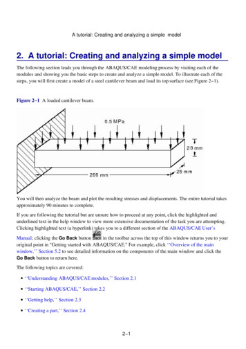
5. The Base System Builder – Configure Processor dialog will be displayed. Select settings tomatch the following: Processor Clock Frequency: 50 MHzProcessor Bus Clock Frequency: 50 MHzDebug Interface: On-chip H/W debug moduleLocal Data and Instruction Memory: 16 KBCache Enabled: uncheckedFigure 2-6. Base System Builder – Configure Processor DialogThe following is an explanation of the settings specified in Figure 2-6: System Wide Setting: Processor Clock Frequency: This is the frequency of the clock driving the processor system. Processor Configuration: Debug I/F: XMD with S/W Debug stub: Selecting this mode of debugging interface introduces asoftware intrusive debugging. There is a 1200-byte stub that is located at 0x00000000. Thisstub communicates with the debugger on the host through the JTAG interface of the OPBMDM module. On-Chip H/W Debug module: When the H/W debug module is selected; an OPB MDMmodule is included in the hardware system. This introduces hardware intrusive debuggingwith no software stub required. This is the recommended way of debugging for MicroBlazesystem. No Debug: No debug is turned on. Users can also specify the size of the local instruction and data memory (BRAM). You can also specify the use of a cache.Embedded Computing and Signal Processing Laboratory – Illinois Institute of Technologyhttp://ecasp.ece.iit.edu12
6. Click Next and the Base System Builder – Configure IO Interfaces dialog will be displayed.Uncheck the LED Bit and LED 7SEGMENTboxes, leaving the remaining devices with thedefault settingsNote: Depending on your screen resolution settings, the Base System Builder – Configure IOInterfaces dialog may show more or less devices in the initial screen than the one shown below.Figure 2-7. Base System Builder – Configure IO Interfaces DialogEmbedded Computing and Signal Processing Laboratory – Illinois Institute of Technologyhttp://ecasp.ece.iit.edu13
7. Uncheck the SRAM 256Kx32 box in the Base System Builder – Configure Additional IOInterfaces dialog screen (Figure 2-8) and click the Next button and the Base System Builder –Add Internal Peripherals dialog
embedded microprocessor (PowerPC). This tutorial will only focus on the soft-core MicroBlaze microprocessor, which can be used in most of the Spartan-II, Spartan-3 and Virtex FPGA families. The hard-core embedded microprocessor mentioned is an IBM PowerPC 405 processor, which is on


![Unreal Engine 4 Tutorial Blueprint Tutorial [1] Basic .](/img/5/ue4-blueprints-tutorial-2018.jpg)