Transcription
Your complete guide to buildingan NMEA 2000 network
ContentsWho are the NMEA and What is NMEA 2000?33333Who are the NMEA?What is NMEA 2000?The Network That CANDeviceNetCertification311NMEA 2000 Network Limitations66667T-Pieces and Termination Resistors999Micro T-PiecesMicro 4-Way T-PiecesConnecting Devices and Extending the backbone101014151617The original Actisense starter KitRIB Starter KitSmall Boat NetworkPower T-PieceMicro Power CableSmall Boat NetworkQuick Network BlockTrunk and Drop CableBulk Cable4131414At a GlanceDetailed OverviewRaymarine SeaTalkNG SolutionNetwork Diagnosis5Powering and fusing the network777811The Quick Network BlockMinimum Network RequirementsCommon PhrasesActisense Starter KitsField Fit Connectors5 Steps to Field Fit Installation SuccessMinimum Network Requirements and Network Limitations44Field Fit Connectors10141213Glanded optionAdequate Power Supply & Termination ResistanceDigging DeeperChecking availibility and accuracy of data on the network
Who are the NMEAand What is NMEA 2000?Who are the NMEA?The NMEA stands for National Marine Electronics Association. In a nutshell, they’re a not for profit organisation whose mission is to improve datacommunications between marine electronics manufacturers. Read more at www.nmea.orgWhat is NMEA 2000?NMEA 2000 is an open standard designed by the NMEA to help them achieve their mission by standardising the messages and connector systemused for devices in the marine industry. There is a common misconception that the term ‘open standard’ means freely available when in fact itmeans that the standard is available to buy at a reasonable cost from their website. It is important to remember that the NMEA is not for profit(NFP) and the standards create an important source of income so that they can continue to exist.The Network That CANNMEA 2000 is based on a system known as CAN which stands for ‘Controller Area Network’. One of the reasons the NMEA chose this system oversomething like Ethernet (for example) which has a much wider bandwidth, and can support RADAR and video, is because CAN has the ability toguarantee message delivery even when the network is 100% loaded. An important feature when you consider that the network is likely to containimportant GPS information.DeviceNetThe NMEA adopted the ‘DeviceNet’ standard for the hardware (cables and connectors) that is used to create an NMEA 2000 network. TheDeviceNet standard was already in use by the automotive and agricultural industries (to name a few) so it is a proven robust system and canwithstand the harsh conditions of the marine environment.CertificationThere is a certification process in place for NMEA 2000. This helps the user to understand that if a device carriesthe NMEA 2000 logo they can rest assured that it is compatible with an NMEA 2000 network and any other ‘NMEA2000 Certified’ device. Some common terms for the user to be aware of are ‘CANbus approved’ or ‘NMEA 2000Compatible’ as these are unlikely to have gone through the NMEA 2000 certification process.‘NMEA 2000 Approved’ is a term used for cables and connectors that meet the requirements for NMEA 2000 as theydo not require the same certification process.
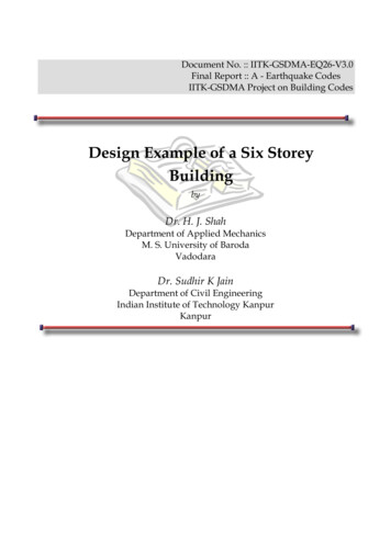
Minimum Network Requirementsand Network LimitationsMinimum Network RequirementsThe following are the essential components of any NMEA 2000 network: Power insertion point - fused. 2 x NMEA 2000 certified devices (at least 1x TX and 1x RX) and a means to connect them to the network. This can be via T-pieces or otherproducts which will be discussed later. Termination resistors - Precisely 2, no more, no less.Common PhrasesYou will hear some common phrases used when discussing NMEA 2000 networks. Here’s what they mean:Backbone: The main trunk of cable that runs through the boat to form the network. T-pieces are connected along the network for devices to plugin to.Instrument drop: The length of cable that connects an NMEA 20000 device to the backbonePGN: Stands for ‘Parameter Group Number’. The messages used by NMEA 2000 devices for sharing information.The diagram below illustrates how an NMEA 2000 network is put together:12v
NMEA 2000 Network LimitationsCable TypeMax LengthMax AmpPower PairData PairPer drop cable6mSum of all drop cables72mMicro/Lite Backbone(Terminator to terminator)100m322 AWG24 AWGMid backbone(Terminator to terminator)250m418 AWG20 AWGMini/Heavy Backbone(Terminator to terminator)250m815 AWG18 AWG
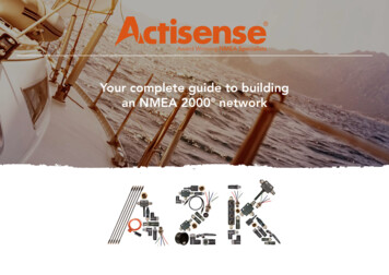
Actisense Starter KitsActisense can provide you with everything you need to get started with an NMEA 2000 network in avariety of flavours. Here’s an outline of their contents. Each individual item will be discussed in moredetail in future episodes, along with other items to complement your NMEA 2000 network.The original Actisense starter Kit Power T-piece - Contains a twin pair of power cables for even power distribution across the NMEA2000 network. 2x T-pieces - for extending the network from the power T-piece and connecting NMEA 2000devices to the network. 2x termination resistors - To maintain signal integrity. 1x 2 metre cable - for extending the length of the backbone if needed or to connect an NMEA2000 device to a T-piece. Fitted with overmoulded DeviceNet standard connectors to protect from water ingress.RIB Starter Kit 1x 4-way T-piece - providing instrument drops for up to 3 devices (one port is used for power). 1x Micro power cord - can be plugged straight in to any available port on the 4-way T-piece to providenetwork power. 2x Termination resistors - To maintain signal integrity. Network can be extended by temporarily removing a terminationresistor, plugging in additional T-pieces and replacing the terminationresistor at the end of the backbone.Small Boat Network Space for 4x instrument drops. Over moulded power cord attached. 2x Termination resistors built in.
Powering and fusing the networkPower T-PieceThe Actisense power T-piece has a twin pair of power wires, one for each side of the T-piece. Both pairs must be connected to a 12/24 Volt powersupply (via fuse panel) so that the electrical load can be distributed evenly.When using 24V systems, a warning must be installed on the network to ensure anyone installing new devices is aware. This is because the NMEA2000 specification doesn’t officially support 24V but this level of power supply can be used if installed devices are capable of supporting it. AllActisense devices support 24V power supplies.The illustration below details the internal wiring of the Actisense power T-piece. Note the pair of positive and negative pins on each side.MaleNET-H 4NET-L 5Shield 1NET-C 3NET-S 2Female4 NET-H5 NET-L1 Shield3 NET-C2 NET-S S Micro Power CableThis cable is designed for small installations that will be used with the RIB Starter Kit so it only has a single pair of power wires. The Micro PowerCable has a Micro DeviceNet connector so that it can be easily plugged in to the most suitable port on the 4-way T-piece provided.The Micro Power Cable should never be used on larger installations.Small Boat NetworkThe power cord for the Small Boat Network is over moulded to the case of a 4-way T-piece to prevent water ingress.Power is available to all 4 ports once the pair of bare wires is connected to a 12V or 24V power supply.
Quick Network BlockThe Actisense Quick Network Block (QNB) provides a versatile and easy to install solution for any NMEA 2000, large or small. This section illustrateshow the QNB can be used for providing power to your network and the added benefits of its features. Other benefits will be shown later in thisdocument. (See “The Quick Network Block” on page 13)Note: The QNB will not regulate the voltage that is being provided to the network.Presence of data LEDFuse 1 status LEDPolarity LEDFusesFuse 2 status LEDPower InsertionPower LED
T-Pieces and Termination ResistorsMicro T-PiecesT-pieces can be connected directly to the Power T or you can use a length of NMEA2000 approved cabling to extend the backbone and join the T-piece to the end ofthe cable. The instrument drop must connected at right angles to the backbone soit is clear what is the backbone and what is an instrument drop.Micro 4-Way T-PiecesThe photos on the right illustrate the different T-piece options available fromActisense. They are shown in actual size (if this PDF has been printed to A4 size)and demonstrate the space saving that the 4-way T-piece can provide.Termination ResistorsAt each end of the backbone a termination resistor must be installed.Each termination resistor is 120 Ohms and is connected in parallelacross the data pair of wires when plugged in to NMEA 2000 approvedcables and connectors. This provides a total of 60 Ohms resitanceacross the network and is essential to data integrity.
Connecting Devicesand Extending the backboneTrunk and Drop CableIf the length of cable required between T-pieces/devices is known, pre-assembled cables can be used for extending the backbone or pluggingin devices to the network. This option saves a lot of time not having to cut the cable and wire a connector to it yourself. Actisense NMEA 2000approved cabling is available in the following sizes: 0.25m0.5m1m2m3m4m5m6m (maximum length that can be used for an instrument drop as defined by the NMEA 2000 specification)8m10mBulk CableIf customised lengths of cable are needed, or lengths of cable greater than 10 metres, bulk cable is availablein 100 metre reels. This can be used together with Actisense field fit connectors.
Field Fit ConnectorsField Fit ConnectorsWhen bulk cable is used a connector will need to be wired to the ends so that the cable can be plugged in to the network or a device. Follow ourfive steps to field fit installation success on the next page that illustrates the best method for installing field fit connectors, including which colourwires connect to which pins. The NMEA 2000 wiring colour system is standardised so the colours and pin numbers will be the same for any wireand connector combination that uses the same DeviceNet standard.Actisense field fit connectors are available as straight or right angled options and in male and female variants to suit any installation requirement.Note the plastic sleeve that coversthe centre pin. This is to prevent thebare wires that extrude from the other4 pins making contact with the copperand creating a short. Not all field fitconnectors have this plastic sleeve.
5 Steps toField Fit Installation Success
The Quick Network BlockAt a GlanceThe next page provides a more detailed overview of the Quick Network Block. Please refer to “Powering and fusing the network” on page 7for full details of the power insertion features of the Quick Network Block.Instrument dropsBackbone connectionsLabels are the same forboth sides and for bothvariants of QNB-1.See the next page for moreinformation on the differentvariants available.Panel mounted wire connectors areavailable as a stand alone productfor creating through bulkhead connections.They can also be used to replace theconnectors in the QNB if needed.Blanking plugs are also available to protectany unused panel mounted wire connectorsfrom water splashes.Wire ColourConnects hield
Detailed OverviewThe Actisense Quick Network Block (QNB) provides a simple ‘network in a box’ solution. It can be used in areas of high instrument density whendevices are up to 12 metres apart from each other (6 metre drop from device to QNB per device). Another popular use for the QNB is withengineers that have a need to create a small NMEA 2000 test environment on a workbench (for example).Raymarine SeaTalkNG SolutionA less obvious benefit to the QNB is the ability to mix and match DeviceNet standard connectors with Raymarine SeaTalkNG (STNG) connectors.As STNG uses exactly the same data as NMEA 2000 but chooses not to use the DeviceNet standard for it’s connector system, adapter cables areneeded to change the connector type when installing STNG devices on NMEA 2000 networks, or vice versa.STNG cables can be stripped back and wired directly to the terminals inside either variant of the QNB-1, which means that you can mix and matchSTNG with DeviceNet. The wiring colours inside STNG cables are the same as DeviceNet cables.Removing the connectors from the PMW variant is not advised as the QNB-1 will lose its watertight integrity. Instead, we recommend simplyconnecting an STNG backbone cable through one or both of the backbone glands to enable the mix & matching options described above.Panel Mounted Wire connector option (PMW)The PMW option is the simplest to install as all the connectors arepre-wired and provide plug & play connectivity. The backbone shouldalways be installed through the glands provided that are furthest fromthe power insertion point.Glanded optionA glanded option of the QNB is available for more customisedinstallations using Actisense bulk cable. A rubber, self-tightening sealinside each gland clamps around the cable when it is installed and thescrew is tightened.
Network DiagnosisNo matter how robust a network is, how simple it is to install, or how well it has been documented and managed there will invariably be issues thatneed tackling at some point. This episode will help to identify some good places to start when diagnosing an NMEA 2000 network.Adequate Power Supply & Termination Resistance Test voltage at entry pointEnsuring the network is receiving a power supply is always the best place to start. As some devices may be powered by the network, knowing thatthese devices are working is a quick win for this test. The power at the entry point should not exceed 14V from a 12V supply. Test voltage at network extremitiesWith network devices using up some of the supplied power and impedance from cabling also dropping the voltage, it is important to know that thevoltage at the end of each backbone leg is adequate. Temporarily remove a termination resistor from the end of the network and use a voltmeterto measure across the NET-S and NET-C pins. The measured value should be at least 9V. The diagrams below will help you find these pins whenusing Actisense connectors.An Actisense Panel Mounted Wire (PMW) connector is a great tool for plugging in to a spare T-piece to quickly identify the correct pins via thewiring colours. It is recommended that each wire from the PMW is terminated inside a terminal block prior to plugging it in to the network asvoltage may be present across the NET-S and NET-C pins.NET-SNET-CNET-LNET-HSHIELD
Check for the correct termination resistanceTurn off network power and check resistance across NET-H and NET-L terminals of any T-piece on the network. The measured resistance shouldread 60 Ohms.If 120 Ohms is measured, only one termination resistor is installed. A second resistor will need to be installed at the opposite end of the networkto the one that is already present.If 40 Ohms is observed, there are 3 termination resistors installed on the network so 1 will need to be removed. If it’s not obvious where the thirdresistor is, check for any devices on the network with installed termination resistors and ensure they are switched off.Network devices with termination resistors installed do not achieve NMEA 2000 certification as this practice can cause confusion on the network.Digging DeeperIf issues remain when the correct power and resistance have been proved on the network, further investigation will be required. Half split methodDisconnect one half of the backbone and move the termination resistor to the new, temporary end of the network. If the issue remains you havenarrowed it down to the half of the network that is still powered and active. If the issue does not remain it is in the half of the network that has beendisconnected. Keep performing this half split method until you are able to narrow it down to a single device, if possible. Don’t forget to move thetermination resistor each time to ensure the network is correctly terminated.Once the issue has been narrowed down, try swapping out t-pieces or cabling with ones that are known to be good. If Field Fit Connectors havebeen used, check the wiring connections inside to ensure that they are correct and firmly secured in place.If possible, check the wiring inside the device is properly and securely terminated, ensuring to observe anti-static precautions if exposing internalelectronics. It is always best to check that this is ok with the device manufacturer before performing this step to ensure you do not void any warranty.If an issue still remains you now know there is a problem with the device and it’s time to contact the manufacturer of that device.
Checking availibility and accuracy of data on the network Actisense NMEA 2000 to PC Gateway (NGT-1)To be able to see all of the data on the NMEA 2000 network and analyse it, you will need to be able to send it to a PC. NMEA 2000 data can notbe read by a PC without the use of a gateway, like the NGT-1.There are two options of NGT-1 available:USB option (NGT-1-USB):This is the easiest to connect to a PC as it can be plugged straight in to your PCs USB port. The NGT-1 will be powered and active once theUSB drivers have been successfully installed. Depending on your OS settings this should happen automatically if you have a working internetconnection. If the USB drivers do not install automatically, the same USB drivers are available on the CD provided with the product or form theNGT-1 downloads page on the Actisense website.ISO option (NGT-1-ISO)The ISO option is for users that prefer a serial connection to their PC, instead of USB. It has bare wires on the PC side for connecting to a serial(RS232) port. The ISO option is powered by the NMEA 2000 network.The default baud rate for both options of NGT-1 is 115200 which can be changed using NMEA Reader. NMEA ReaderNMEA Reader is software that lets you see all of the data being sent to your PC from the NMEA 2000 network via the NGT-1. There are also optionsfor configuring Actisense devices. NMEA Reader is freely available to download from the Actisense website. Actisense ToolkitToolkit is new software from Actisense that is currently used for configuring the Engine Monitoring Unit (EMU-1) from Actisense. It will soon supportconfiguration of all configurable Actisense products and will replace NMEA Reader when the ‘Data View’ feature has been added.For more information on how to use the NGT-1, NMEA Reader or Toolkit, please refer to the manual at actisense.com
4 5 1 3 2 4 5 1 3 2 _ S _ Female NET-H NET-L Shield NET-C NET-S Male NET-H NET-L Shield NET-C NET-S Powering and fusing the network Power T-Piece The Actisense power T-piece has a twin pair of power wires, one for each side of the T-piece.