Transcription
Aerospace Science and Technology, Volume 73, February 2018, Pages 85-95DOI:10.1016/j.ast.2017.09.002Civil Turbofan Engine Exhaust Aerodynamics: Impact ofBypass Nozzle After-body DesignIoannis Goulos ,Tomasz Stankowski, David MacManusPropulsion Engineering CentreSchool of Aerospace, Transport and ManufacturingCranfield UniversityBedfordshire, MK43 0AL, UKAbstractIt is envisaged that the next generation of civil large turbofan engines will be designed for greater bypass ratios whencompared to contemporary architectures. The underlying motivation is to reduce specific thrust and improve propulsive efficiency. Concurrently, the aerodynamic performance of the exhaust system is anticipated to play a key role in the success offuture engine architectures. The transonic flow topology downstream of the bypass nozzle can be significantly influenced bythe after-body geometry. This behavior is further complicatedby the existence of the air-flow vent on the nozzle after-bodywhich can have an impact on the performance of the exhaustsystem. This paper aims to investigate the aerodynamics associated with the geometry of the bypass nozzle after-body and toestablish guidelines for the design of separate-jet exhausts withrespect to future large turbofan engines. A parametric geometry definition has been derived based on Class-Shape Transformation (CST) functions for the representation of post-nozzle-exitcomponents such as after-bodies, plugs, and air-flow vents. Thedeveloped method has been coupled with an automatic mesh generation and a Reynolds Averaged Navier–Stokes (RANS) flow solution method, thus devising an integrated aerodynamic designtool. A cost-effective optimization strategy has been implementedconsisting of methods for Design Space Exploration (DSE), Response Surface Modeling (RSM), and Genetic Algorithms (GAs).The combined approach has been deployed to explore theaerodynamic design space associated with the bypass nozzleafter-body geometry for a Very High Bypass Ratio (VHBR) turbofan engine with separate-jet exhausts. A detailed investigationhas been carried out to expose the transonic flow mechanisms associated with the effect of after-body curvature combined with the Corresponding and lead author, Building 52, Room 233, Cranfield University, E: i.goulos@cranfield.ac.uk, T: 44 (0) 1234 75 4648Philip Woodrow, Christopher SheafInstallation AerodynamicsRolls-Royce plcDerby , DE24 8BJ, UKimpact of the air-flow vent. A set of optimum curved after-bodygeometries has been obtained, with each subsequently comparedagainst their respective conical representation. The obtained results suggest that no significant performance improvements canbe obtained through curving the nozzle after-body relative to thecase of a conical design. However, it is shown that the application of surface curvature has the potential to unlock new partsin the design space that allow analysts to reduce the requiredafter-body length without any loss in aerodynamic performance.The developed approach complements the existing tool-set of enabling technologies for the design and optimization of futurelarge aero-engines, consequently leading to increased thrust andreduced Specific Fuel Consumption (SFC).Keywords: Turbofan engine aerodynamics, Computationalfluid dynamics, Propulsion integration, Class-shape transformation functions, Exhaust nozzles, Annular after-bodies, Design optimization, Transonic flow aerodynamicsNomenclatureRoman SymbolsṁNozzle mass flow, kg/secAArea, m2BypassCDBypass exhaust nozzle discharge coefficientCoreCDCore exhaust nozzle discharge coefficientCVOverallExhaust system overall velocity coefficientCDventVent exhaust nozzle discharge coefficientFG , FNGross and net propulsive force, Nh2Bypass nozzle exit height, mhventVent exhaust nozzle exit height, m2LLength, m1I. Goulos et al.Published by Elsevier. This is the Author Accepted Manuscript issued with:Creative Commons Attribution Non-Commercial No Derivatives License (CC:BY:NC:ND 4.0).The final published version (version of record) is available online at DOI:10.1016/j.ast.2017.09.002. Please refer to any applicable publisher terms of use.
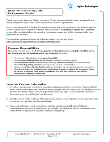
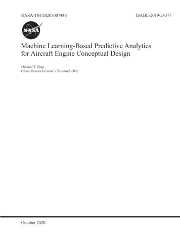
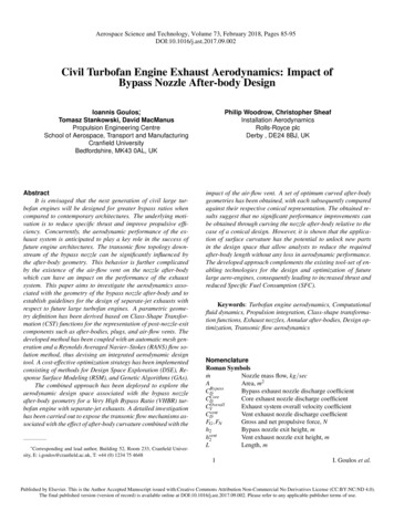
laconicalf terbodyNormalizedconicalafter-bodylength,conicalLa f terbody R f anexitlventNormalized axial location of air-flow vent exit, exitLventLaconicalf terbodyM Mach number (free-stream)outMventAir-flow vent exhaust nozzle exit Mach numberNPearsonPearson’s product-moment of correlationPPressure, PaRcurveCurvature radius, m Aexit 1Rcon diExhaust nozzle con-di ratio, AthroatR f anFan blade tip radius, mRcurveInner aeroline curvature radius at bypass nozzlenozzleexit, mRcurveInner aeroline curvature radius at vent exhaust nozventzle exit, mGreek Symbols θaTfEterbody Bypass nozzle after-body trailing edge overturning angle, θaTfEterbody θaconicalf terbody , degexit exitBypass nozzle exit over-turning angle, θnozzle θnozzleθaconicalf terbody , degexit θventVent exhaust nozzle exit over-turning angle, exit θ conical , degθventa f terbodyTE θventVent exhaust nozzle after-body trailing edge overT E θ conical , degturning angle, θventa f terbodyκnozzleNormalized curvature radius ratio at bypass nozzleRcurveexit, nozzleh2κventNormalized curvature radius ratio at vent nozzleRcurveexit, venthvent2conicalConical after-body angle, degθa f terbodyθaTfEterbodyBypass nozzle after-body trailing edge angle, degTEVent nozzle after-body trailing edge angle, degθventexitθnozzleAngle of inner aeroline at bypass nozzle exit, degexitθventAngle of inner aeroline at vent exhaust nozzle exit,degSubscripts()0Referring to stagnation flow conditions()ConicalReferring to the conical after-body design()CurvedReferring to the curved after-body design()ExitReferring to the nozzle exit()stReferring to static flow conditions()ventReferring to the air-flow vent1 Introduction1.1 BackgroundCurrent design trends for civil turbofan engines dictate continuously lowering specific thrust to improve propulsive efficiency and reduce Specific Fuel Consumption (SFC) [1]. Thisis done by lowering the Fan Pressure Ratio (FPR) and increasṁbypassing the engine By-Pass Ratio (BPR ) which results in aṁcorehigher-amount of mass flow exhausted through the bypass nozzle ṁbypass , relative to the core engine flow ṁcore . Due to theFGassociated withlarge ratio of gross to net propulsive forceFNthe next generation of civil aero-engines [2], small variations inthe aerodynamic behavior of the exhaust system may have detrimental impact on overall engine performance [3]. Consequently,the aerodynamic design of the exhaust system is key to the success of future engine architectures.Medium to large civil turbofan engines usually employ somevariation of a separate-jet exhaust system as opposed to mixednozzles. An illustration of an axi-symmetric engine geometry equipped with a separate-jet exhaust system is presented inFig. 1. Within the context of this work, the term “exhaust system” refers to the bypass and core ducts and nozzles, as well asany post-exit components located downstream of the nozzle exits. The bypass and core flows are separated by the bypass nozzleafter-body, also referred to as the “core after-body”. The bypassand core streams meet and mix downstream of the core nozzleexit. An air-flow vent is usually located on the core after-bodyand is used to exhaust secondary air-flows from the engine core.A protruding core plug is employed to reduce the core after-bodylength required for a given core nozzle exit area.The gross propulsive force FG produced by the exhaust system can be substantially influenced by the aerodynamic pressureand viscous forces exerted on the walls of the bypass duct andnozzle, core after-body, and protruding core plug. Dusa et al. [4]reported that for high-bypass ratio turbofan engines, the grossthrust loss due to non-isentropic flow conditions can be of theorder of 1.5–2.0% relative to the ideal case of fully-expandedisentropic flow. To establish a standard accounting process, itis common practice to compare the actual nozzle performancewith that of an ideal nozzle through the definition of the nondimensional discharge and velocity coefficients, CD and CV , respectively [5, 6]. Thus, from a design perspective, it is desirablethat the geometry of the exhaust system is optimized to ensurethe maximum aerodynamic performance in terms of CD and CV .The concept of exhaust design optimization for civil aeroengines has been formerly tackled by Goulos et al. [7, 8]. However, previous work done on the topic by the authors [7, 8] aswell as other researchers, [9–11], has been based on the implicitassumption of a simplified conical representation for the exhaustcomponents located downstream of the bypass nozzle, such asthe core after-body and plug (Fig. 1). However, the resultant tran2I. Goulos et al.
Bypass nozzle exitIntake FanfaceSpinnerBypassduct inletBypass nozzle (core)after-body Core ductinletAir-flow ventCore nozzleexitCore plugFigure 1. Example axi-symmetric housing geometry for a civil gasturbine aero-engine with separate-jet exhaustssonic flow topology downstream of the bypass exhaust nozzlecan be significantly influenced by the after-body curvature [12].This behavior is further complicated by the existence of the airflow vent on the core after-body (Fig. 1) which can have an impact on the aerodynamics of the exhaust system and, inevitably,on overall SFC. Hence, it is essential that the aerodynamic impact of after-body curvature is meticulously explored to enablethe global optimization of the exhaust system.1.2Aerodynamic design of nozzle after-bodiesThe literature available in the public domain covering theaerodynamic design of exhaust nozzles, after-bodies, and plugsis relatively scarce. Furthermore, it is predominantly founded ongrounds of experimental testing done on single-stream exhaustnozzles with conical or circular-arc after-bodies.The Engineering Sciences Data Unit (ESDU) published anempirical method for the estimation of subsonic pressure dragcoefficients of after-bodies with central propulsive jets [13, 14].The ESDU method is based on a series of prediction proceduresfor the base, boat-tail, and total after-body pressure drag coefficients of single-stream nozzles. Available design parametersinclude the boat-tail angle, nozzle exit diameter, base area, andmaximum nozzle diameter. However, the ESDU method is notable to predict actual nozzle performance in terms of dischargeor velocity coefficients. Furthermore, it is only applicable to axisymmetric exhausts with circular-arc or similar boat-tails fittedwith convergent or parallel single-stream nozzles without plugs.Compton [15–17] and Compton and Runckel [18] performed an extensive campaign of experimental investigations onthe aerodynamic behavior of single-stream jet exhausts for turbojet engines with conical after-bodies. The effect of nozzle exitbase recession as a means of reducing base pressure drag wasreviewed in Ref. [17]. A series of different designs were investigated experimentally, such as; flat, concave, open, and semitoroidal concave. It was concluded that increasing base concavity may have a favorable effect on base pressure up to a thresholddepending on nozzle boat-tail angle.Peace [12] developed a numerical approach for the estimation of viscous and compressible flows around single-stream aswell as co-axial exhaust nozzles and after-bodies. The bulk aerodynamic analysis was carried out using an inviscid and compressible Euler flow-solver [19]. The baseline method was modified to include viscous effects due to boundary-layers on theafter-body walls and shear-layers in the jet wake using the formu-lation developed by Williams [20]. The combined method wasdeployed to investigate the aerodynamic behavior of “circulararc-type” as well as conical after-bodies for single-stream nozzles and co-axial jet exhausts, respectively. Numerical predictions were compared with experimental measurements in termsof static pressure distributions on the after-body surfaces. Peacenoted that for coaxial jets, reasonably good agreement is obtainedwhen the nozzles operate un-choked. The observed agreementseemed to deteriorate for the choked-nozzle cases where a strongadverse shock topology may manifest on the core after-body.1.3Scope of present workIn light of the aforementioned context, this paper aims todevelop a holistic approach for the Design Space Exploration(DSE) and optimization of conceptual separate-jet exhaust systems for the next generation of civil aero-engines. The developed method extends previous work done by the authors on thetopic [7, 8] through the implementation of a parametric geometry definition for the post-nozzle-exit components. The proposedmethod inherits the intuitiveness and flexibility of Class-ShapeTransformation (CST) functions originally developed for airfoilparameterization [21–23], and extends their applicability to therepresentation of nozzle after-bodies, plugs, and air-flow vents.The combined approach has been coupled with an automaticmesh generation and a RANS flow solution method, thus formulating an integrated aerodynamic design tool. A computationally efficient optimization strategy has been developed comprising methods for Design Of Experiment (DOE), Response Surface Modeling (RSM), as well as Genetic Algorithms (GAs).Within this work, the computational framework previouslydeveloped [7, 8] has been applied to explore the exhaust designspace of a VHBR turbofan, representative of the next generationof civil large aero-engines. The effect of after-body surface curvature and air-flow vent design on the aerodynamic behavior of aseparate-jet exhaust system has been investigated. The transonicflow mechanisms that influence the aerodynamic performance ofseparate-jet exhaust after-bodies have been determined. A series of optimum curved after-body designs have been obtainedand compared against their respective conical baselines to assessthe aerodynamic benefit associated with the effect of after-bodycurvature. Furthermore, an attempt has been made to arrive to adefinitive remark considering the influence of after-body curvature that is applicable throughout the global design space including all air-flow vent positions and exit area requirements.2MethodologyThis work aims to adapt and expand the capability of thecomputational framework previously developed by Goulos etal. [7, 8] for the aerodynamic design of civil aero-engines withseparate-jet exhausts. The employed tool has been named GEMINI (Geometric Engine Modeler Including Nozzle Installation).GEMINI encompasses a series of fundamental modeling meth3I. Goulos et al.
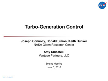
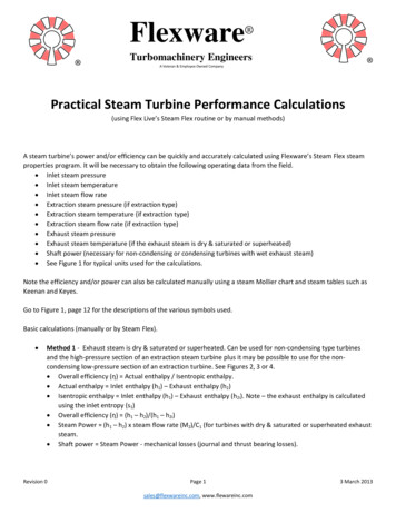
ods originally developed for: engine performance analysis [24],exhaust duct and nozzle aeroline parameterization [7, 21–23],viscous-compressible flow solution [25, 26], as well as DSE andMulti-Objective Optimization (MOO) [8].2.1GEMINI: Exhaust system aerodynamic designGEMINI initiates the design process based on a userprescribed set of engine cycle and geometric design parameters.The aero-thermal behavior of the employed cycle is evaluatedfor a series of key operating points within the operational envelope of interest. The required aero-thermal analysis is carried outusing the zero-dimensional (0D) engine performance simulationtool Turbomatch [27] originally developed by Macmillan [24].The purpose of this process is two-fold: (a) It determines theflow-capacity requirements for the bypass and core exhaust nozzles, and (b) It establishes boundary conditions for the flow properties at the inlet of the bypass and core exhaust nozzles (Fig. 1).Having determined the required nozzle flow-capacities,GEMINI applies an inverse design approach to derive a 2D axisymmetric representation of the aerodynamic lines for the bypass and core nozzles, including their downstream after-bodies(Fig. 1). An automatic mesh generation tool is subsequentlydeployed to compute the axi-symmetric, multi-block, structuredgrid [25] for the engine geometry including the separate-jet exhaust system. Hence, among others, GEMINI establishes theComputational Fluid Dynamics (CFD) domain upon which theviscous and compressible flow-field can be resolved.The flow solver ANSYS Fluent [26] is employed as the current aerodynamic analysis method. Computations are carried outusing a RANS CFD approach coupled the k ω Shear-StressTransport (SST) turbulence model [28]. The Green-Gauss nodebased method is used for calculation of the flow-field gradients.A second-order accurate upwind scheme is used for the spatialdiscretization of primitive variables as well as turbulent kineticenergy k and specific dissipation rate ω. Thermal conductivity(κ) is computed according to kinetic theory. Variable gas properties are employed using an 8th order polynomial expression forthe calculation of specific heat capacity as a function of statictemperature [26]. The calculation of dynamic viscosity is carriedout based on Sutherland’s law [26]. Bardina et al. [29] showedthat the k ω SST model can moderately over-predict the onsetand amount of flow separation under the influence of an adversepressure gradient. Thus, the employed CFD approach is expectedto provide conservative estimates of aerodynamic performancewith regards to design regions where flow-separation may occur.Having obtained a converged flow solution, the numericaldata are automatically post-processed to determine the exhaustsystem’s performance metrics of interest. These include the byCore ,pass and core nozzle discharge coefficients, CDBypass and CDrespectively, as well as the overall exhaust system velocity coefficient CVOverall [7]. The CFD methods and approach employed inGEMINI have been verified and validated by Goulos et al. [7].2.2Exhaust nozzle design and analysisGEMINI incorporates a parametric geometry definitionbased on the Class-Shape function Transformation (CST)method originally proposed by Kulfan [21,22] and further developed by Qin [23]. The employed approach developed by Gouloset al. [7] inherits the intuitiveness and flexibility of Qin’s CSTvariation [23] and extends its applicability to the parametric representation of exhaust ducts and nozzles. The adapted formulation allows to express the bypass/core duct, nacelle exhaust, andafter-body aerolines as functions of intuitive parameters [7].2.3Parametric geometry definition of axi-symmetricexhaust nozzle after-bodiesTo investigate the aerodynamic behavior of the bypass nozzle after-body, a suitable parametric geometry definition is required. The employed approach has to be flexible and allow sufficient generality to explore a wide-range of geometries withoutover-constraining the design space. Furthermore, the requireddesign flexibility has to be satisfied using a small number of Degrees of Freedom (DOFs), also referred to as “design variables”.The underlying necessity is to mitigate the so-called “curse ofdimensionality” [30] which can manifest when analyzing multidimensional spaces with a high number of design variables.At this point, it is clarified that the nature of the present DSEapproach requires to limit the dimensionality of the design spacein order to maintain an acceptable accuracy of RSM approximation to be used for subsequent optimizations. However, theexploration of high-dimensional aerodynamic design spaces hasbeen enabled with the advent of the discrete adjoint compressibleRANS formulation [31].Specifically, Heath et al. [9] were ableto apply a non-linear gradient-based optimization approach coupled with the discrete adjoint formulation of the RANS equationsfor the shape optimization of a dual-stream plug nozzle using upto 20 design variables. Thus, gradient-based optimization methods have been shown to cope adequately with high-dimensionalspaces in the context of aerodynamic shape optimization.Within this work, the CST variation developed by Gouloset al. [7] for the parametric geometry definition of exhaust ductsand nozzles, is extended to the design of after-bodies. Figure 2demonstrates the parametric geometry definition used to establish a generalized representation for the bypass nozzle after-body.The topology of a datum exhaust featuring a simplified conicalafter-body with half-cone angle θaconicalf terbody , is shown in Fig. 2(a).It can be noted that the overall after-body geometry comprisestwo main components: (a) The part located upstream of the airflow vent and (b) the part positioned downstream of the air-flowvent. The employed approach allows to control the curvature parameters of each part independently. The design variables controlling the curvature of each component are shown in Figs. 2(b)and (c) for the upstream and downstream sections, respectively.Figures 2(b) and (c) demonstrate that a total of three (3) variables are incorporated to control the surface curvature for each4I. Goulos et al.
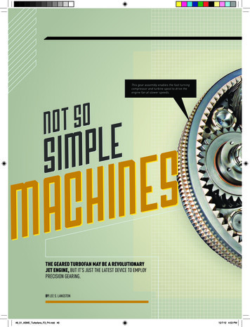
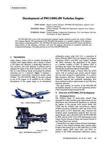
Red dots represent control pointsafter-body section. With respect to the after-body portion locatedupstream of the air-flow vent, Fig. 2(b) shows that the selecteddesign variables can be outlined as follows: (a) the bypass nozexitzle inner annulus exit angle θnozzlewhich controls the angle ofthe inner aeroline at the nozzle exit, (b) the bypass nozzle innerannulus exit curvature radius Rcurvenozzle which defines a finite innerline radius of curvature at the nozzle exit, and (c) the after-bodyTrailing Edge (TE) angle θaTfEterbody . The datum conical afterbody geometry with half-cone angle θaconicalf terbody is also shown using a grey dashed line. To establish an intuitive representation ofthe curved after-body geometry, the identified design variablesare related to the corresponding conical geometry as follows:exitexit θnozzle θnozzle θaconicalf terbody(1a) θaTfEterbody θaTfEterbody θaconicalf terbody(1b)κnozzle Rcurvenozzleh2Bypass duct inneraerolineNozzleExitouter planeaerolineAir-flow ventNozzleinner aeroline(1c)where h2 is the bypass nozzle exit height as shown in Fig. 2(a).The same approach is applied to derive a parametric geometrydefinition for the after-body part located downstream of the airflow vent as demonstrated in Fig. 2(c). This results in anotherexit , θ T E , and κthree (3) intuitive design variables: θventvent .ventThe parametric representation outlined above results in a total of six (6) design variables, as shown in Figs. 2(b) and (c).These can control the surface curvature with respect to both afterbody sections. As such, they can be employed to derive the associated geometric constraints that the curved after-body linesneed to satisfy. The CST variation described by Goulos et. al [7]is subsequently applied using the prescribed constraints to derivethe curved after-body geometry. The employed approach ensurescurvature continuity throughout the entire after-body shape dueto the infinitely differentiable nature of CST functions [21, 22].The proposed method can be used to design a wide-rangeof after-body geometries including concave, convex, and mixedconvex–concave or concave–convex designs using a relativelysmall number of intuitive design variables. Figure 3 demonstrates the capability of the adapted formulation to capture thediversity inherent in the design space of conceptual exhaust afterbody geometries with finite curvature variations.2.4Bypass duct outerChargingaerolineplaneDesign space exploration and optimizationTo perform a thorough investigation with respect to the aerodynamic impact of after-body curvature, the Design Space Exploration (DSE) environment of GEMINI has been utilized [8].GEMINI incorporates a robust and computationally efficient optimization strategy that accounts for the inherent non-linearityof transonic flow aerodynamics and mitigates the computationalcost associated with numerous CFD simulations. The optimization strategy of GEMINI has been described in Ref. [8].Figure 2. Parametric geometry for bypass nozzle after-body: (a) exhaust system overview, (b) after-body portion located upstream of airflow vent, (c) after-body portion located downstream of air-flow ventThe DSE environment of GEMINI consists of mathematicalmethods for Design Space Exploration (DSE), Response SurfaceModeling (RSM – also referred to as surrogate modeling), andMulti-Objective Optimization (MOO). The DSE procedure comprises two major aspects; (a) an initial Design of Experiment(DOE) which aims to strategically populate the design space,and (b) the mathematical formulation of Response Surface Models (RSMs) using the computed DOE sample data. A DOE is asystematic approach to get the maximum amount of informationout of a given number of samples. The Latin Hypercube Design(LHD) algorithm [32] has been selected for this work. Havingcompleted the LHD DOE approach, RSMs can be subsequentlystructured using the obtained DOE results as model inputs. Interpolation using Gaussian Processes Regression [33] (KrigingInterpolation) has been the method of choice for this work.The structured RSMs can subsequently be used to approximate the aerodynamic behavior of the exhaust system. GEMINI5I. Goulos et al.
Air-flow vent(a)Table 1.ConcaveConvexCycle parameter. inlet BypassP0Pamb stinlet CoreP0PstambBPRAir-flow vent(b)Concave/ConvexConvex/ConcaveAir-flow ventAir-flow vent(c)(d)Figure 3. Example bypass nozzle after-bodies designed using the developed method including concave, convex, and mixed geometriesis based on the deployment of RSMs as drivers during the optimization process instead of using direct CFD simulations. Thisis done to mitigate the excessive computational cost associatedwith multiple CFD evaluations. The classical Leave-One-Out(LOO) cross-validation method [34] is employed to assess thepredictive accuracy of the structured RSMs prior to using them inan optimization environment. After successful approximation ofthe simulation method’s response to design inputs, the availabledesign space can be systematically explored for optimum solutions. The employed optimization approach has to be immune tothe danger of being trapped between locally optimum solutions.Hence, the deployment of a global method is required. The Nondominated Sorting Genetic Algorithm II (NSGA-II) originallyproposed by Deb et al. [35] has been selected to carry out theoptimizations reported in this paper.3Results and discussionA comprehensive numerical investigation was carried out toassess the effect of bypass nozzle after-body curvature (Fig. 3)on the exhaust aerodynamics of a civil aero-engine. The baseline power-plant architecture was defined to be representative offuture large turbofans. The engine cycle was structured usingpublicly available information [36]. The cycle parameters andcomponent efficiencies were selected according to an estimated“year 2025 to 2030” technology level [37, 38].The geometric topology used for the datum exhaust systemis illustrated in Fig. 2(a). The baseline exhaust system has beenpre-optimized at design-point mid-cruise conditions using thenumerical approach developed by Goulos et al. [8] assuming aconical after-body representation. Guynn et al. [36] showed thatwith respect to future civil aero-engines, the employed FPR atnear mid-cruise conditions can range between 1.3 and 1.5, depending on cycle architecture and BPR. For the the purpose ofthis work, an FPR of 1.4 has been selected to reflect the middleof the FPR range for a VHBR turbofan engine with BPR 16.For M 0.85, the selected FPR value results in a bypass nozzleNPR of approximately 2.2. The bypass and core nozzle pressure ratios, along with the free-stream conditions are also listedBaseline engine operating parametersValueUnit2.2–1.5–16–FPR1.4–M 0.85–10668mAltitudein Table 1 for consistency. These denote the boundary conditionsspecified for the aerodynamic computations presented in this paper. The derivation and analysis of the employed thermodynamicengine cycle has been further described by Goulos et al. [7].3.1 Aerodynamic effect of after-body surface concavityA parametric analysis was initially carried out to understandthe fundamental aerodynamic mechanisms associated with theinfluence of after-body surface concavity (Fig. 3). As elaboratedin section 2.3 of this paper, the after-body geometry comprisestwo sections: (a) The part located upstream of the air-flow vent(Fig. 2(b)) and (b) the part positioned aft of the vent nozzle exit(Fig. 2(c)). The position of the air-flow vent on the after-bodycan have a significant impact on the aerodynamic behavior of theexhaust system [7, 8]. The flow exhausted through the vent isusually of low total pressure and Mach number. As such, it issensitive to adverse pressure gradients generated by surface concavity with a high potential for flow-separation. Furthermore, thegeometric “radial step” at the vent nozzle exit (Fig. 2) can alterthe transonic flow topology on the after-body. Thus, dependingon the vent location, different flow mechanisms may manifestand impact on the performance of the exhaust system.To understand the sensitivity of exhaust performance withrespect to the effect of after-body curvature, two baseline deexit θ T E signs with conical after-bodies ( θnozzlea f terbody 0 andexitTE θvent θvent 0 ) were employed based on the datum configuration shown in Fig. 2(a). The sole difference between thetwo baseline exhaust designs is the axial location of the ventexitLventexit nozzle on the core after-body lvent, where Laconicalf terbodyLaconicalf terbodythe total after-body length from bypass nozzle exit to core nozzle exit. For the first datum exhaust geometry (D1), the vent isexit 0.85) and in close proximpositioned at an aft location (lventity to the after-body TE and core nozzle exit. With regards tothe second datum design (D2), the vent is placed upstream atexit 0.25, near the vicinity of the bypass nozzle exit.lventThe associated flow solutions for the baseline exhaust sys6I. Goulos et al.
exit tems are presented in Figs 4(a) and (b) for the first (D1: lventexit 0.25) case, respectively. It can be0.85) an
Referring to the conical after-body design Curved. Referring to the curved after-body design Exit. Referring to the nozzle exit st. Referring to static flow conditions vent. Referring to the air-flow vent. 1 Introduction 1.1 Background. Current design trends for civil turbofan engines dictate con-tinuously lowering specific thrust to improve .