Transcription
VM‐AV/WPWhite PaperTheory, Application, and Sizing of Air ValvesTable of ContentsIntroduction. . . . . . . . . . . . . . . . . . . . . .Three Basic Types of Air Valves. . . . . . .Air Release Valves. . . . . . . . . . . . . . . . .Air/Vacuum Valves. . . . . . . . . . . . . . . .Combination Air Valves. . . . . . . . . . . . .Air Valve Locations Along a Pipeline. . .Air/Vacuum Valve Sizing. . . . . . . . . . . .Air Release Valve Sizing. . . . . . . . . . . . .Summary. . . . . . . . . . . . . . . . . . . . . . . . .References. . . . . . . . . . . . . . . . . . . . . . .2233445788Val‐Matic Valve & Mfg. Corp. www.valmatic.com valves@valmatic.com PH: 630‐941‐7600Copyright 2018 Val‐Matic Valve & Mfg. Corp.
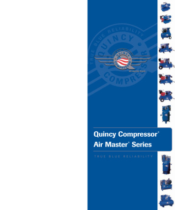
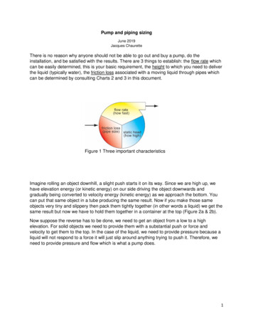
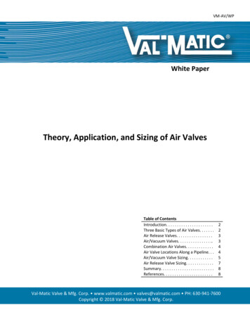
Theory, Application and Sizing of Air ValvesINTRODUCTIONOne of the most misunderstood aspects of the water and wastewater industry is the presence of air in apipeline and its impact on operations. Many operational problems, especially at the time of initial start‐up, including damaged equipment, as well as faulty instrumentation readings, are blamed on inadequatethrust blocking, improper pipeline bedding, etc. But in reality, many of these problems are not causedby improper installation of the line, but by failure to de‐aerate the line. Properly de‐aerating thepipeline with the use of automatic air valves will safeguard it from air‐related problems.Air in a pressurized, operating pipeline has three primary sources. First, prior to start‐up, the line is notempty; it is full of air. As the line fills with liquid, much of this air will be pushed downstream andreleased through hydrants, faucets, etc. but a large amount will become trapped at system high points.This phenomenon will occur because air is lighter than water and therefore, will collect at high points.The second source of air is the incoming water itself. Water contains approximately 2% air by volumebased on normal solubility of air in water (7). The dissolved air will come out of solution with a rise intemperature or a drop in pressure, which will commonly occur at high points due to the increase inelevation. Finally, air can enter through mechanical equipment such as pumps, fittings, and valves whenvacuum conditions occur.Trapped air can have serious effects on system operation and efficiency. As air pockets collect at highpoints, a restriction of the flow occurs which produces unnecessary headloss and energy consumption.As shown in the Figure, trapped air forms a long pocket along the pipe descent with a constant depth“d”. Since the air is at the same pressurealong the air pocket, it can be shown thatthe headloss is equal to the vertical heightof the pocket or dimension “H” (1). Apipeline with many air pockets can imposeenough restriction to stop all flow. Also,sudden changes in velocity can occur fromthe movement of air pockets. Whenpassing through a restriction in the linesuch as a control valve, a dislodged pocket of air can cause surges or water hammer. Water hammercan damage equipment or loosen fittings and cause leakage. Finally, corrosion in the pipe material isaccelerated when exposed to the air pocket, which can result in premature failure of the pipeline.Air is sometimes removed from a line with a manual vent or fire hydrant during initial start‐up but thismethod does not provide continual air release during system operation nor does it provide vacuumprotection. Today, municipalities use a variety of automatic air valves at the pump discharge and alongthe pipeline.THREE BASIC TYPES OF AIR VALVESThere are three basic types of air valves standardized in American Water Works Association (AWWA)Standard C512‐15: “Air‐Release, Air/Vacuum, and Combination Air Valves for Water and WastewaterService.”It is important to understand the functions and limitations of each valve type so that valves can belocated and sized properly for a pipeline.2
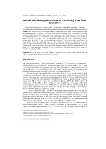
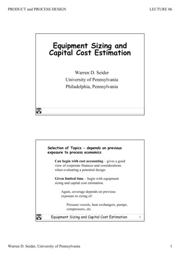
Theory, Application and Sizing of Air ValvesAIR RELEASE VALVESAir Release Valves are probably the best known air valve and are typically furnishedin sizes ½ in. (13 mm) through 3 in. (76 mm). The valve has a small precision orificeAir Release Valvein the range of 1/16 in. (1.6 mm) to ½ in. (13 mm) to release air under pressurecontinuously during pipeline operation. The Air Release Valve has a float to sensethe presence of air and a linkage mechanism that gives the float mechanicaladvantage in opening the orifice under full pipeline pressures.Air Release Valves have a limited capacity for admitting and exhausting air becauseof their small orifice. For this reason, most pipeline locations require both AirRelease and Air/Vacuum Valves for exhausting and admitting large volumes of air.Air Release ValveAIR/VACUUM VALVESAn Air/Vacuum Valve is installed downstream of pumps and at high points toexhaust large volumes of air during pump start‐up and pipeline filling. The valvealso will admit large volumes of air to prevent a vacuum condition from occurring inthe pipeline and to allow for draining. A float in the valve rises with the water levelto shut off the valve when the air has been exhausted. Upon the loss of pressuredue to draining, line break, or column separation, the float will drop and allow air toreenter the pipe. It is important to note that under normal operation, the float isheld closed by the line pressure and will not relieve accumulated air. An AirRelease Valve is needed to relieve air during system operation.Air/Vacuum ValveThere are two variations of Air/Vacuum Valves that warrant discussion. First,Air/Vacuum valves can be equipped with a Slow‐Closing Device which controls theflow into the valve to reduce surges in the valve. The Slow‐Closing Device is useful athighpoints where column separation or rapid changes in velocity occur. Columnseparation can be predicted by computer transient analysis, but the followinggeneral guidelines can be used to help locate Slow‐Closing Devices.Slow‐Closing Device1. When the flow velocity is greater than 8 ft/sec (2.4 M/sec), the surge potential can be as high as 400PSI (2760 kPa). Also, when the fill velocity exceeds 2 ft/sec (0.6 M/sec) high surges can result.2. High points where a vacuum forms on pump shut‐off may exhibit rapid flow reversal.3. Systems where the time for the water column to reverse is less than the critical time will see highsurges even from small changes in velocity. The critical time is defined as 2L/a, where “L” is the pipelength and “a” is the elastic pressure wave speed (3).4. Fast closing pump discharge check valves may prevent slam but still cause line surges.5. Systems with booster pump stations can see great fluctuations in line velocities on power failure.6. If the pipeline discharge creates a siphon on shut‐down, rapid flow reversal can be expected.Second, a Well Service Air Valve is an Air/Vacuum Valve equipped with a ThrottlingDevice or a Slow‐Closing Device (4" and larger valves) for use with vertical turbinepumps. These pumps start against an empty pump column and a closed pump checkvalve and therefore start rapidly and accelerate the fluid. Well Service Air Valvesrequire special consideration during sizing.Dual PortThrottling Device3
Theory, Application and Sizing of Air ValvesThe Throttling Device (3" and smaller valves) controls the air discharge rate so that the pressure surgecaused by the pump water column reaching the closed check valve is minimized. The Throttling Devicehas a second independent vacuum port to allow air flow back into the line after pump shutdown so thatthe static suction water level can be restored without allowing a vacuum to form in the pump column.The Dual Port Throttling Device should have an open vacuum port separate from the exhaust port sothat the air flow into the device is not restricted by exhaust piping.COMBINATION AIR VALVESThe Combination Air Valve combines the functions of both the Air/Vacuum and Air Release Valves and isan excellent choice for high points. A Combination Valve contains both a small air release orifice and alarge air/vacuum port in one assembly. On smaller valves, usually less than 8 in. (200 mm), the float andlever mechanism are contained in a single body design. On larger sizes, a dual body design consisting ofan Air Release Valve piped to an Air/Vacuum Valve is furnished as a factory assembled unit.Single Body CombinationDual Body CombinationSingle body units have the advantage of being more compact and typically less costly. Dual body unitsare advantageous for Air Release Valve sizing and maintenance because the Air/Vacuum Valve is still inoperation while the Air Release Valve is isolated and under repair. By combining various sized AirRelease and Air/Vacuum Valves, a Dual Body Combination Valve can be made for almost any application.Some designers use only Combination Air Valves on a pipeline because all air valve functions areincluded and a mistake in field installation will not leave the pipeline unprotected.AIR VALVE LOCATIONS ALONG A PIPELINEAir valves are installed on a pipeline to exhaust air and admit air to prevent vacuum conditions andair‐related surges. The AWWA Air Valve Manual recommends Air Valves at the following points along apipeline (4).1. High Points: Combination Air Valve.2. Long Horizontal Runs: Air Release or Comb. Valve at 1250 to 2500 ft. (380 to 760M) intervals.3. Long Descents: Combination Air Valve at 1250 to 2500 ft. (380 to 760M) intervals.4. Long Ascents: Air/Vacuum Valve at 1250 to 2500 ft. (380 to 760M) intervals.5. Decrease in an Up Slope: Air/Vacuum Valve.6. Increase in a Down Slope: Combination Air Valve.7. Transient Locations: Combination/Slow‐Closing Device or Vacuum Breaker/Air Release.8. Flow Meters: Air Release upstream.9. Well or Vertical Turbine Pumps: Air/Vacuum/Slow‐Closing Device or Throttling Device.4
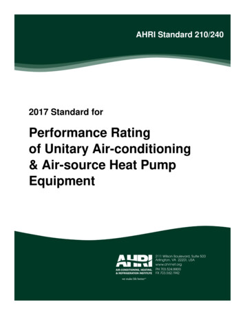
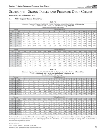
Theory, Application and Sizing of Air ValvesSAMPLE PIPELINE PROFILE ILLUSTRATING VALVE LOCATIONSNo. DescriptionRecommended TypesNo.Description12345678Air/Vac & Slow‐ClosingCombinationNo Valve RequiredNo Valve RequiredAir/Vac or CombinationCombinationAir Rel or CombinationCombination910111213141516Decr. DownslopeLow PointLong AscentIncr. UpslopeDecr. UpslopeHigh PointLong DescentDecr. UpslopePump DischargeIncr. DownslopeLow PointIncr. UpslopeDecr. UpslopeBeg. Horiz.HorizontalEnd Horiz.Recommended TypesNo Valve RequiredNo Valve RequiredAir/Vac or CombinationNo Valve RequiredAir/Vac or CombinationCombination & Slow‐ClosingAir Rel or CombinationAir/Vac or CombinationAlso, on very long horizontal runs, Air Release and Combination Air Valves will be used alternately alongthe pipeline. It should be noted that Combination Valves can be used at any location instead of AirRelease or Air/Vacuum Valves to provide added air release capacity on the pipeline.It is important to establish a smooth pipeline grade and not follow the terrain or an excessive number ofAir Valves will be needed. The designer must balance the cost of air valve locations with the cost ofadditional excavation. Finally, depending on the pipeline velocity and size, minor high points andchanges in grade can be ignored because the velocity may scour the air from the pipeline (3).AIR/VACUUM VALVE SIZINGSome publications list a rule of thumb that suggests Air/Vacuum Valves be 1 in. (25 mm) per 1 ft. (0.3 M)of pipe diameter (4). So a 4 ft. (1.2 M) diameter line would have a 4 in. (100 mm) diameter valve. Basedon over thirty years of successful air valve application, Val‐Matic has developed sizing criteria that formthe basis for the following methodology. The methodology is based on sizing the air/vacuum valve fortwo conditions: admitting air to prevent a vacuum in the pipeline and exhausting air during filling of thepipeline.The Air/Vacuum or Combination Air Valve should be capable of admitting air after power failure or linebreak at a rate equal to the potential gravity flow of water due to the slope of the pipe. The flow ofwater due to slope can be found by the Darcy‐Weisbach equation:5
Theory, Application and Sizing of Air Valvesv (2 g H / K)½(5)where:v Flow velocity, ft/secg gravity, 32.2 ft/sec2H Change in Elevation, ft.K Resistance coefficient, dimensionless fL/d 2.5(the 2.5 represents entrance, exit, and some piping losses)f friction factor of pipe (iron .019, steel .013, plastic .007)L Change in Station Points (length of run), ft.d pipe ID, ft.The gravity flow due to slope is calculated for every pipe segment. For stations where there is a changein up slope or down slope, the difference between the upstream and downstream flows is used forsizing because the upper segment feeds the lower segment and helps prevent a vacuum from forming.When steel or any collapsible pipe is used, it is important to determine if there is a risk of pipelinecollapse due to the formation of a negative pressure. The following equation finds the external collapsepressure of thin wall steel pipe using a safety factor of 4. A safety factor of 4 is recommended to takeinto account variances in pipe construction, variances in bury conditions, and possible dynamic loads.P where:P T D 16,250,000 * (T / D)3(6)Collapse Pressure, psi.Pipe Thickness, in.Pipe Diameter, in.Collapse may also be a concern on large diameter plastic or ductile iron pipe. The pipe manufacturershould be consulted to provide maximum external collapse pressures.The air valve should be capable of admitting the flow due to slope without exceeding the lower of thecalculated pipe collapse pressure or 5 PSI (35 kPa). 5 PSI (35 kPa) is used for sizing to remain safelybelow the limiting sonic pressure drop of 7 PSI (48 kPa). Manufacturers provide capacity curves for theirvalves which can be used to select the proper size. The capacity of an Air/Vacuum Valve can beestimated using:q 678 * Y * d2 * C * [DP * P1 / (T1 * Sg) ]½(5)where:q Air Flow, SCFMY Expansion Factor.79 (for vacuum sizing).85 (for exhaust sizing at 5 psi).93 (for exhaust sizing at 2 psi)d Valve Diameter, inDP Delta Pressure, psiThe lowe
air/vacuum valve sizing Some publications list a rule of thumb that suggests Air/Vacuum Valves be 1 in. (25 mm) per 1 ft. (0.3 M) of pipe diameter (4).File Size: 365KBPage Count: 8