Transcription
Multi-Fidelity Multidisciplinary Whole Engine Thermo-MechanicalDesign OptimizationToal, D. J. J., Keane, A. J., Benito, D., Dixon, J. A., Yang, J., Price, M., Robinson, T., Remouchamps, A., & Kill,N. (2014). Multi-Fidelity Multidisciplinary Whole Engine Thermo-Mechanical Design Optimization. Journal ofPropulsion and Power, 30(6), 1654-1666. https://doi.org/10.2514/1.B35128Published in:Journal of Propulsion and PowerDocument Version:Peer reviewed versionQueen's University Belfast - Research Portal:Link to publication record in Queen's University Belfast Research PortalPublisher rightsCopyright 2014 the authors. The final published version is available in the AIAA electronic 28General rightsCopyright for the publications made accessible via the Queen's University Belfast Research Portal is retained by the author(s) and / or othercopyright owners and it is a condition of accessing these publications that users recognise and abide by the legal requirements associatedwith these rights.Take down policyThe Research Portal is Queen's institutional repository that provides access to Queen's research output. Every effort has been made toensure that content in the Research Portal does not infringe any person's rights, or applicable UK laws. If you discover content in theResearch Portal that you believe breaches copyright or violates any law, please contact openaccess@qub.ac.uk.Download date:03. Aug. 2022
Multi-Fidelity Multidisciplinary Whole EngineThermo-Mechanical Design Optimization1 and Andy J. Keane2David J.J. ToalUniversity of Southampton, Southampton, SO17 1BJ, U.K.3Diego Benito and Je ery A. DixonRolls-Royce Plc., Derby, DE24 9HY, U.K.Jingbin Yang and Matthew PriceRolls-Royce Plc., Bristol, BS34 7QE, U.K.Trevor Robinson4Queen's University Belfast, Belfast, BT9 5AH, U.K.Alain Remouchamps and Norbert KillLMS Samtech, a Siemens business, Liege, BelgiumTraditionally the optimization of a turbomachinery engine casing for tip clearance has involved either 2D transient thermo-mechanical simulations or 3D mechanicalsimulations. The following paper illustrates that 3D transient whole engine thermomechanical simulations can be used within tip clearance optimizations and that thee ciency of such optimizations can be improved when a multi- delity surrogate modeling approach is employed. These simulations are employed in conjunction with a rotor sub-optimization utilizing surrogate models of rotordynamics performance, stress,mass and transient displacements and an engine parameterization.1234Senior Research Fellow, Faculty of Engineering & EnvironmentProfessor, Faculty of Engineering & EnvironmentChief of Thermal SystemsLecturer, School of Mechanical & Aerospace Engineering1
NomenclatureC Co-Kriging correlation matrixd No. of dimensionsd Di erence between expensive and cheap dataE[I(x )] Expected improvement atf Analytical test functionp Hyperparameter controlling degree of smoothnessR Kriging correlation matrixs2 Estimate of mean square errorx Vector of design parametersX Complete sampling plany Vector of objective function valuesθ Hyperparameter controlling rate of correlation decreaseµ Meanρ Co-Kriging scaling factorσ2 Varianceϕ Concentrated log-likelihoodx Subscripts:c Cheap functiond Di erence functione Expensive functionI. IntroductionModern gas turbine engine design is a continual battle to reduce emissions, fuel consumption,cost and noise. In this drive for improved performance, design optimization techniques are increasingly being seen as an important tool for nding novel designs. Any design optimization, however,is only as good as the simulation, or simulations, used to assess the performance of each design. Inorder to correctly model the interactions between each of the major sub-assemblies de ning a gasturbine it is necessary, for example, to employ a whole engine model which models not only me-2
chanical but also thermal loads. Such simulations are extremely expensive to perform and thereforedi cult to encapsulate within an e ective design optimization.The following paper aims to demonstrate the feasibility of employing whole engine transientthermo-mechanical simulations within an automated design optimization loop towards the exit ofthe preliminary design phase. The movement of such high delity analyzes to this stage in the designcycle aims to improve the level of continuity between the preliminary and detailed design stageswhile reducing the amount of rework required during detailed design where costs are considerablyhigher.The presented whole engine design optimization demonstrates a number of novel concepts which,to the authors' knowledge, have never before been employed in such an optimization. These includethe application of whole engine transient thermo-mechanical simulations in the optimization of a gasturbine, a multi- delity surrogate modeling approach to this design optimization, a parameterizationof the engine capable of maintaining the correct boundary condition tags and a multi-disciplinarysub-optimization of the rotor.A. Speci c Fuel Consumption OptimizationThe overall aim of the presented design optimization is to reduce the speci c fuel consumption(SFC) of the presented test engine by improving the high pressure compressor tip clearances. Asdemonstrated throughout the literature,[1 4] the clearance between the casing and the tip of acompressor or turbine blade has a considerable impact on the fuel consumption of an engine. Whilee orts have been made in the past to control the impact of these clearances through changes in casingshape or topology,[1, 5] previous studies have employed either simpli ed shell models of the wholeengine in a mechanical analysis[5] or a combination of 2D axisymmetric transient whole engineanalysis and 3D blading and rotor/stator deformations[3].Only using a fully transient thermo-mechanical simulation of the whole engine can tip clearances be accurately predicted[2, 3]. WhileBenito et al.[2] presented the prediction of local tip clearances using 3D transient thermo-mechanicalsimulations, this analysis was not used within an optimization to drive design improvements andthe analysis was restricted to only the intermediate pressure (IP) compressor casing. The design3
optimization presented within this paper aims to employ simulations of a similar delity to those ofBenito et al.[2] to improve tip clearances and therefore SFC.As discussed by Benito et al.[2] and Arkhipov et al.[3], whole engine transient thermo-mechanical(WETTM) analyzes can be considerably expensive to perform. In order to make the application ofsuch simulations feasible within a design optimization, either the simulation needs to be as cheapas possible (including both the runtime and the setup time) or the number of such simulationsperformed needs to be minimized.In general, the cost of any nite element analysis (FEA) canbe controlled through a reduction in the number of degrees of freedom of the mesh. The schemeof Makem et al.[6], for example, has already been demonstrated to o er a considerable reductionin the number of degrees of freedom when meshing part of the presented test engine and could beemployed along with the approaches discussed in the present paper to further reduce the cost of anySFC optimization.B. Surrogate ModelingThe direct application of global optimization schemes, such as genetic algorithms[7] or simulatedannealing[8] is completely infeasible in this case.Such schemes can require many thousands offunction evaluations to successfully converge to the global optimum.Even with the analysis ofmany WETTM simulations in parallel on a compute cluster, the optimization would still takeseveral months to perform.An alternative approach is to generate a surrogate model from a relatively small number ofsimulations distributed throughout the design space. Surrogate models, otherwise known as responsesurfaces or metamodels, aim to provide an analytical representation of the response of a quantityof interest throughout the design space.Due to their analytical nature, such surrogates can besearched cheaply using a global optimization algorithm.The application of a surrogate modelpredicting SFC would therefore considerably reduce the number of WETTM simulations required.A similar approach was adopted by Voutchkov et al.[5] with surrogate models of SFC, mass andother objectives used to drive a multi-objective optimization.The performance of a surrogate assisted design optimization is generally related to the accuracy4
with which the surrogate predicts the true response. If the response is well predicted, the optimization can quickly nd a promising design. However, if the surrogate is inaccurate, the optimizationcan waste evaluations of the true function improving the model and exploring the design space before converging. A simple way of improving the accuracy of any surrogate model is to include moredata within that model. This, however, translates to more WETTM simulations and therefore anincrease in the cost of the optimization.An alternative is to employ a multi- delity approach whereby information from a small number of high delity simulations is augmented by additional information from a large number oflower delity simulations.Multi- delity approaches have been successfully employed throughoutthe literature[9 13] and have been demonstrated to be very e ective at improving the quality of thenal design or reducing the total simulation e ort required during an optimization, compared tothe low- and high- delity design, respectively. In the following paper we explore the application ofsuch a multi- delity approach to whole engine optimization.C. Whole Engine ParametrizationThe ability to perform batch modi cations of geometry is one of the main cornerstones ofany engineering design optimization.Modern computer aided design (CAD) software o ers theability to create parametric models which can be easily manipulated by, for example, altering themagnitude of a dimension. While the modi cation of the geometry is a trivial matter, maintainingthe links between this geometry and the simulation(s) used to asses the performance of the designcan pose a number of signi cant problems. This is especially the case if the topology of the geometrychanges. To maintain continuity, even in the face of such changes, a programmatic approach to theparameterization was adopted, with the presented test engine parameterization developed using theSiemens NX Open C application programming interface (API).The NX Open C API is a exibleand powerful programming interface included within the Siemens NX CAD software package[43]which gives the user access to all of the software's capabilities and has been used in the past tocreate exible parametric geometry[14] and feature extraction systems[6, 15, 16].5
D. Multi-Disciplinary Rotor Sub-OptimizationThe tip clearance within a compressor or turbine is a function of both the movement of thecasing and the rotor.In the case of Voutchkov et al.[5], the design of the rotor was xed andonly the casing design was changed as part of the optimization.In the present optimization, abi-level approach is taken whereby for every new casing considered the rotor is redesigned in asub-optimization. This sub-optimization takes into account constraints on rotor mass, stress androtordynamics performance when maximizing overall engine SFC. Such an approach results in anactive trade-o between rotor and casing mass.As the top level optimization progresses, massremoved from the rotor can be used to improve the sti ness of the casing and vice versa.Of course, any analysis performed as part of the rotor sub-optimization will increase the totaltime spent evaluating each new casing design.Given that an identical rotor sub-optimization isperformed for every new casing design, surrogate models of rotor stress, mass and rotordynamicsperformance can be easily substituted thereby considerably reducing the sub-optimization cost. Thechange in tip clearance and therefore the change in SFC with each new rotor design is dependenton the displacement of the casing. As this is not known before the WETTM analysis is performed,it is impossible to construct a surrogate model of rotor SFC a priori. Instead the presented optimization employs a novel surrogate modeling approach to predict the transient displacements of thecompressor blade platforms modeled in the rotor simulation. The rotor sub-optimization thereforeuses this surrogate model to predict the platform displacements for each rotor design which canthen be combined with the displacements of the casing from the WETTM simulation to calculatetip clearance and therefore SFC.E. Optimization Strategy OverviewTo summarize, the optimization presented within this paper and illustrated graphically in Figure 1, employs an NX Open C based parameterization of the test engine which maintains continuity between the engine geometry and the boundary conditions of the FEA simulation. With anew engine generated from the parametric model the design is passed to a whole engine transientthermo-mechanical simulation, or if a multi- delity approach is adopted, a whole engine steady-state6
SurrogateModel of RotorDisplacementsStartOptimizationDefine a Designof ExperimentsPerform TransientThermo-MechanicalAnalysisPerform RotorSubOptimisationGenerate EngineCasingGeometryPerform SteadyState MechanicalAnalysisSearch SurrogateModels ForPromising ached?YesFinal Casing &Rotor DesignFig. 1 Multi- delity optimization work ow.mechanical simulation. Displacements from these simulations are used in conjunction with surrogatemodels predicting transient displacements, mass, stress and rotordynamics performance in a rotorsub-optimization. The resulting SFCs and total engine masses are then used to construct surrogatemodels which are used in a global optimization. Promising casing designs are then assessed and usedto improve the accuracy of the surrogates with the process repeating until a prede ned stoppingcriterion has been reached.Given the importance of single and multi- delity surrogate modelling to the optimizations considered, the following article begins by describing in detail the mathematics behind both Krigingand, its multi- delity variant, Co-Kriging. The parametric model of the test engine is then describedbefore the various simulations and post-processing operations are considered in turn. The transientthermo-mechanical simulations of the static engine casings and rotors are discussed and the postprocessing operations used to calculate the SFC of each new engine design are described. Finally,the details of the 2D rotordynamics simulation are presented before being applied in conjunctionwith the thermo-mechanical simulations in a simple two variable optimization of the rotor.Themethodologies used in the construction of the surrogates used in the rotor sub-optimizations arepresented and their accuracy assessed. A comparison of the global accuracy of single and multi delity surrogate models of engine SFC is then presented before these methods are compared usingfour and ten variable bi-level optimizations of the whole engine.7
II. Kriging & Co-KrigingPopularized by Sacks et al.[17] for use in the prediction of deterministic computational responses,Kriging, of the surrogate modeling techniques within the literature[18 20], is perhaps one of the mostpopular due to its predictive accuracy and useful prediction of the error in the model.A Kriging model is constructed based on the assumption that when two points are close togetherin the design space their objective function values will be similar. This is modeled by assuming thatthe correlation between two pointsxiandxjis(Rij Corr [Y (xi ), Y (xj )] exp d )θ (l)10(l) xi (l) (l)xj p,(1)l 1whereθ (l)andp(l)represent the, so called, hyperparameters of thelthdesign variable and de nethe rate of correlation decrease and the degree of smoothness, respectively. These hyperparametersare de ned through a maximization of the likelihood on the observed dataset,y,which, aftersimpli cation[21], equates ton1ln(σ̂ 2 ) ln( R ),22(2)1(y 1µ̂)T R 1 (y 1µ̂)n(3)ϕ withσ̂ 2 andµ̂ 1T R 1 y1T R 1 1de ning maximum likelihood estimates of the variance,σ̂ 2(4)and mean,µ̂,respectively. A hybridizedparticle swarm algorithm, similar to that of Toal et al.[22], is employed within the surrogate modeling toolbox of the proprietary optimization software, OPTIMATv2[5, 22 25], to optimize thehyperparameters in all Kriging and Co-Kriging models presented within this article.Given an optimal set of hyperparameters, the vector of correlations,point,x ,r(x ) , between an unknownand the known sample points can be used in conjunction with the mean to calculate theprediction of the Kriging model at the unknown point,y(x ) µ̂ r T R 1 (y 1µ̂).8(5)
This predictor can be used by any global optimization routine to search the design space for anoptimum. Alternatively an estimate of the mean square error of the Kriging model,[]s2 (x ) σ̂ 2 1 r T R 1 r ,(6)can also be calculated at an unknown point and used to update the surrogate model in areas ofmaximum error thereby improving the model's global accuracy.This error estimate can also beemployed in another popular updating criterion - expected improvement ([26]),[(ymin y(x ))E[I(x )] 1 erf2( Here erf() denotes the error function andymin y(x ) s 2ymin)][] (ymin y(x ))2s exp.2s22π(7)denotes the objective function value of the bestunconstrained design found so far. An exhaustive search of the expected improvement over a designspace attempts to locate an update point which is most likely to result in an improvement over thecurrent best design and therefore attempts to balance both exploration and exploitation of the designspace. Evaluating the true objective function at the optimum indicated by the predictor can resultin the optimization becoming trapped in a local minimum thereby resulting in a sub-optimal design.Using the expected improvement update criterion, on the other hand, has been demonstrated[21, 26]to allow the optimization to escape from such local optima thereby guaranteeing that the globaloptimum will be reached if given enough function evaluations.Co-Kriging extends the Kriging concept described above to deal with multiple levels of simulation delity.Using the approach of Kennedy and O'Hagan,[27] the high delity response isapproximated by multiplying a Gaussian process representing the low delity response by a scalingfactor,ρ,and adding a second Gaussian process of the di erence between the high and low delitydata,Ze (x) ρZc (x) Zd (x).IfXeandXc(8)represent the expensive and cheap data respectively, then the covariance matrix σc2 Rc (Xc , Xc )C ρσc2 Rc (Xe , Xc ) ρσc2 Rc (Xc , Xe )ρ2 σc2 Rc (Xe , Xe ) σd2 Rd (Xe , Xe ), Cis(9)where the correlations are assumed to be of the same form as Eq. 1. Given that there are now twoGaussian processes in the model, there are twice as many hyperparameters to determine comparedto the standard Kriging model above. The scaling parameter9ρmust also be determined.
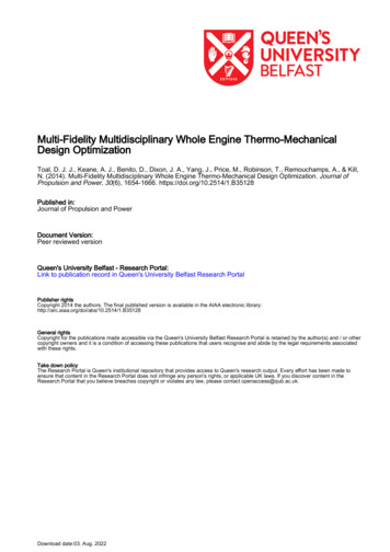
As the low delity data is considered to be independent of the high delity data, the samemaximization of likelihood process used to determine the hyperparameters for the standard Krigingmodel can be employed. The hyperparmeters of the di erence model can then be optimized using asimilar process but with the objective functionyreplaced by the di erence between the expensiveand scaled cheap data,d ye ρyc (Xe ).(10)With the hyperparameters optimized, the covariance matrix, Eq. 9, can be calculated and used inconjunction with a column vector,c,of covariances of an unknown point to the known points topredict the high delity response at that unknown point,ye (x ) µ̂ cT C 1 (y 1µ̂),(11)with the mean now,µ̂ whereY1T C 1 Y,1T C 1 1(12)is a combination of the known low and high delity responses. As per the standard Krigingmodel, the Co-Kriging model provides an estimate of the mean square error,s2e (x ) ρ2 σ̂c2 σ̂d2 cT C 1 c 1 1T C 1 c,1T C 1 1(13)which can be used in the calculation of expected improvement[28].Figure 2 helps to illustrate the advantages of Co-Kriging over Kriging in the prediction of asimple one dimensional analytical test function. The thick solid black line of Figure 2 represents ahigh delity, or expensive, function,fe (6x 2)2 sin(12x 4),(14)while the thinner solid black line represents a low delity, or cheap, function,fc 0.5fe 10(x 0.5) 5.(15)Constructing a Kriging model using the four expensive design of experiments (DoE) points illustrated results in a surrogate model which does not accurately represent the true function and would10
20f (x)ef (x)15f(x)10cExpensive DoECheap DoEKriging ModelCo Kriging Model50 5 1000.20.40.60.81xFig. 2 Analytical example of Kriging Co-Kriging (recreatedfrom Forrester et al.[28]).mislead any optimization. However, combining 11 additional data points evaluated using the lowdelity function with the same four expensive points produces a surrogate model which very accurately represents the true function. In fact, the Co-Kriging prediction is almost indiscernible fromthe true function. In this case the likelihood optimization for the di erence model results in a valueofρ 2x 1.thereby producing a di erence model which reduces linearly in magnitude fromx 0toWhen this model is combined with the cheap prediction this has the e ect of increasing themagnitude of the cheap function more, closer tox 0than tox 1which therefore translates thecheap function into something closely resembling the expensive function.III. Test Engine & ParameterizationThe majority of engineering design optimizations assess the performance of a new design usingsome form of computational simulation. Be it computational uid dynamics or nite element analysis, generally these simulations require some form of discretized geometry as an input. Modi cationsto the geometry are then re ected in the mesh and therefore in the results of the simulation which11
(b)(a)Fig. 3 Baseline 3D engine casing (a) and compressor intercasing with additional sti ening rings and modi ed thrust linkages (b).indicates if the modi cation was successful. The task of creating the simulation model from the geometry can be in itself an expensive process, and the objective must be to automatically propagatethe analysis information from one analysis model to the next iteration. Whilst the ability to modifygeometry is important in its own right, ensuring that the modi ed geometry is still compatible withthe simulation is perhaps more important and, in some cases, can be di cult to achieve.If themodel is not compatible with the previous simulation setup, the amount of manual e ort requiredto make it so can make the entire process infeasible.Consider for example the baseline engine design illustrated in Figure 3(a). In order to performa WETTM simulation of this engine geometry, boundary conditions must be applied to everyface of the illustrated solid body.To achieve this, each face is tagged" or named" within theCAD environment with these tags then being used to assign boundary conditions within the FEAsimulation. Naturally, if any of these tags should be altered or deleted, the boundary conditionswould not be applied correctly and either the simulation would fail or, perhaps more seriously, thesimulation would complete successfully but the results would be unreliable. Within an automateddesign optimization loop, where there can be minimal human intervention, such issues can resultin the optimization being led into the incorrect region of the design space. Given the cost of the12
WETTM simulations employed here, this is something that must be avoided at all costs.Such issues can be avoided by using the CAD package in one of two ways. The optimization canbe constrained to only consider modi cations to the geometry which do not result in changes thatalter the geometry tags. However, this is almost impossible to identify a priori and, where enforced,it would restrict modi cations of engine to changes in casing thickness, ange heights and widthsand some topological changes such as the number of aerodynamic struts at the compressor exit.Unfortunately the inclusion of additional sti ening rings around the casing, which may possibly o erimprovements in tip clearance and SFC could not be investigated. The inclusion of such a featureresults in a split along the cylindrical face to which it is attached thereby creating a new cylindricalface with no tag and therefore no associated boundary conditions. Nolan et al.[16] describe a methodfor de ning boundary conditions on computed interfaces so that they can be propagated onto newtopological faces when they occur, but this requires the model to be represented in a certain way.The second approach is to create the parametric model in such a manner as to embed intelligenceregarding the boundary condition tags so that if topology changes are su cient to remove tags orresult in faces with no tags this can be accounted for and automatically corrected. Given that theeventual design optimization aims to explore topology changes such as the inclusion of additionalsti ening rings this is the approach that is taken here.The parameterization of the test engine illustrated in 3(a) was developed using the SiemensNX6 Open C API. Rather than create the geometry in a traditional manner using the graphical userinterface (GUI), the operations to create or modify the geometry were written into a C programwhich could be run from within NX. As the high pressure compressor (HPC) casing, illustratedin Figure 3(b), was the main subject of the WETTM optimization, it was important to makethe parameterization as exible as possible.The Open C program therefore contained all of thecommands to create the HPC casing from scratch. This included operations, for example, to drawlines and revolve them to create casing faces, create blends between anges and casings and extrudeaerodynamic sti eners.By altering the values contained within a simple text le more than 30parameters de ning the shape of the HPC casing could be altered including casing thicknesses,ange heights and widths (see Figure 4), the position, number and size of internal aerodynamic13
Fig. 4 Example modi cations to casing thicknesses and sti ener thicknesses and heights.struts and the circumferential position and setting angle of thrust linkages (see Figure 3(b)). Theprocess of generating the geometry completely from scratch using the Open C program each timeis, in this case, insigni cant compared to the cost of the FE analysis.As well as these changes, the input le will also control the addition ofnfully parametricsti ening rings applied to the outer faces of the HPC casing. The position, height and thicknessof each additional sti ening ring can be controlled via the input le.Figure 3(b) illustrates themodi cation of the baseline HPC casing geometry shown in Figure 3(a) through the addition of sixadditional sti ening rings to the casing.As described above, the addition of sti ening rings in such a manner will typically result inthe creation of new cylindrical faces with no tags.When the rings are applied in this instance,the creation and modi cation of faces is tracked and the new face has the correct tag applied. Byemploying an NX Open C geometry parameterization, the tags, and therefore the correct applicationof boundary conditions, can be explicitly accounted for and issues arising from such topology changescan be minimized.The test engine geometry consists of a total of ve separate solid bodies: the fan casing, HPC14
Fig. 5 Two dimensional rotor geometry.Fig. 6 Illustration of the rear HPC rotor parameterization.casing, high pressure turbine (HPT) casing, low pressure turbine (LPT) casing and turbine bearingstruts. Of these solid bodies, only the HPC casing is completely parametric with the baseline HPT,LPT and struts read into the model unaltered. While the main part of the fan casing is read inunaltered, the Open C program is used to apply a fully parametric fan case mounting bracket tothe top of the casing. While the ability to modify the location of the mount is embedded within theOpen C program it, is not employed in any of the optimizations presented within this paper.As previously stated, the WETTM optimization aims to employ a sub-optimization of the rotor.In order to perform this optimization, or in this case, generate the information necessary to createthe surrogate models to perform the optimization, a geometry parameterization is required.As per the casing parameterization described above, the 2D rotor, illustrated in Figure 5 isparameterized using an NX Open C program. In this case, the angle and thickness of the rear HPCcone and the thickness of the shaft can vary. With a simple text le, once again, used to alter thedesign parameters. Figure 6 illustrates the extent of the modi cations to the rotor which can be15
made.IV. Transient Thermo-Mechanical SimulationsAs brie y noted in the introduction, the performance of the test engine is assessed using atransient thermo-mechanical analysis. The setup of this analysis closely follows the work of Benitoet al.[2] with all engine casings simulated simultaneously rather than just the IP compressor casing.The WETTM analysis is performed using the proprietary Rolls-Royce FEA package SC03, adescription of which can be found in Armstrong and Edmunds[29]. SC03, in this case, is used toperform the analysis and pre-process the engine geometry generated by the NX Open C program.Upon creation of the geometry in NX, a Parasolid le is exported before CAD x is used to convertthe Parasolid into SC03's native geometry input format.SC03 then reads in the geometry an
di cult to encapsulate within an e ective design optimization. The following paper aims to demonstrate the feasibility of employing whole engine transient thermo-mechanical simulations within an automated design optimization loop towards the exit of the preliminary design phase. The movement of such high delity analyzes to this stage in the design