Transcription
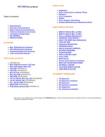
RCI 2950 Service ManualPARTS LISTS Table of Contents SpecificationsControls and ConnectionsBasic Programming ProceduresTechnical Analysis of the circuitsTransistors Voltage ChartRCI SECRETSREPAIR TRICKSRADIO MODIFICATIONS DIAGRAMS Main PCB Schematic DiagramCPU PCB Schematic DiagramChassis Exploded View DrawingInter-connection Diagram PCB Layouts and Parts (EPT295013Z)Main PCB Parts Layout Top ViewMain PCB Copper Side ViewLCD PCB (EPT295021Z)CPU PCB (EPT295043Z)MIC UP/DW (EPT295080Z)MIC Jack PCB (EPT295070Z)SWR PCB (EPT360040Z)VR (A) PCB RF/MIC VOL/SQ (EPT295050Z)VR (B) PCB RF/CAL (EPT295060Z)CH / Switch PCB (EPT295090A)MODE PCB (EPT295090Z)Push Button Switch PCB (EPT295031Z)CapacitorsCoils, Transformers, Crystals, FiltersResistorsIC's, TransistorsDiodesWire, Jumpers, ConnectorsChassis, Miscellaneous & Mechanical Parts MODIFY FOR 26 Mhz -32 MhzMODIFY FOR 25 Mhz -33 MhzHam to CB Mode ModificationINCREASE YOUR POWER ! !HEAVY SWINGER Mod (Modulation)TUNE UP/MODUpgrading AM detectionINCREASE AUDIOAdd an Automatic SQUELCHBATTERY PROBLEMSCLARIFIER MODCAR'S LIGHTER InstallLCD & LEDSMIKE WiringProtect From Polarity InversionsMOD FOR FASTER SCAN SPEEDEXTERNAL S-METERTALK BACK MODIFICATIONTONE MODIFICATIONALIGNMENT PROCEDURES TX AlignmentTX Alignment LocationsRX AlignmentRX Alignment LocationsPLL AlignmentPLL Alignment LocationsEste manual es una recopilación de las mejores páginas web. Radioaficion.com,. No ofrece ninguna garantia sobre el contenido del mismo, ni se hace responsable de lamanipulación indebida de los equipos
RCI-2950 SpecificationsKey Features·Full Band Coverage - Covers the 10 Meter Amateur Band from 28.0000 to 29.6999 MHz.·All Mode Operation - Operates on USB, LSB, CW, AM and FM.·Brightness Control - Four Step LCD brightness control for easy viewing under any condition.·Repeater Offset Switch - Gives you standard offsets for repeater operation.·Programmable Frequencies - Allows you to program up to 10 individual frequencies. Includes battery backup.·Built in Dual VFO - Choose steps of 10kHz, lkHz or 100Hz, manual or scan·RIT - Receiver Incremental Tuning to fine tune the receive frequency up to /- 3kHz.·Squelch - Cuts off or eliminates receiver background noise in the absence of incoming signals.·Noise Blanker - Greatly reduces repetitive impulse noise.·RF Gain Control - Reduces the gain of the receiver under strong signal conditions to prevent overloading.·RF Power Output Selector - Lets you select transmitting output power·External Speaker Connection - Place a speaker anywhere for convenient listening.·PA Mode - Use an external speaker for a mobile PA system.·LCD Display - Large, easy to read backlit LCD display.·Multi-Function LCD Meter - Indicates transmit power, receive signal strength, modulation, SWR Calibration and SWR.SpecificationsGeneral·Frequency Range: 28.0000 29.6999 MHz·Tuning Steps: 100Hz, 1kHz, 10kHz, 100kHz, 1MHz·Emission Types: USB, LSB(A3J), CW(A1), AM(A3), FM(F3)·Frequency Control: Phase-Locked Loop Synthesizer·Frequency Tolerance: 0.005%·Frequency Stability: 0.001%·Operating Temperature Range: 0 to 40 degrees C.·Antenna Impedance: 50 Ohms·Microphone: 400 Ohms, Dynamic PTT·Speaker: 8 Ohms, 2 Watts·Display: Digital Frequency, LCD·Meter Function: RF Output, Receive Signal Strength, Modulation, SWR Calibration, SWR·Power Requirements: 13.8 Volt DC Negative GroundTransmitter·Antenna Connector: UHF TYPE, 50 Ohm·RF Transmit Modes: USB, LSB, CW, AM, FM·RF Output Power: USB, LSB (25W); CW (8W); AM/FM (8W)·Spurious Emissions: -50dB·Carrier Suppression (SSB Modes): -50 dBReceiver·Sensitivity for 10dB SINAD: AM 0.5uV·Sensitivity for 10dB SINAD: USB/LSB/CW 0.15uV·Sensitivity for 12dB SINAD: FM 0.25uV·Image Rejection Ratio: 65dB·AGC Figure of Merit: SSB/CW/AM 80dB for 50mV for 10dB Change in Audio Output·Audio Output Power: 2.5 Watts
RCI-2950 Controls and ConnectionsINTRODUCTIONThis section explains the basic operating procedures for the RCI-2950/2970 amateur 10 meter mobile transceiver.CONTROL & CONNECTIONS1. FREQUENCY SELECTOR:This control is used to select a desired transmit and receive frequency. It enables you to make a continuous tuning over the entirerange of the transceiver.2. RF POWER CONTROL:This control enables you to adjust RF power continuously over the range of 1 watt through 25 watts(RCI-2970: 10 watts through 100 watts).3. MIC GAIN CONTROL:This control adjusts the microphone gain in the transmit and PA modes. This feature is designed for use in ah-ambient noise environment or to maxize talk power.4. ON/OFF VOLUME CONTROL:Turn clockwise to apply power to the radio and to set the desired listening level.5. SQUELCH CONTROL:This control is used to control or eliminate receiver background noise in the absence of an incoming signal.For maximum receiver sensitivity, it is desired that the control be adjusted only to the point where the receiver background noiseis eliminated. Turn fully counterclockwise then slowly turn clockwise until the receiver noise disappears. Any signal to be receivedmust now be slightly stronger than the average received noise. Further clockwise rotation will increase the threshold level which asignal must overcome in order to be heard. Only strong signals will be heard at a maximum clockwise setting.
6. RF GAIN CONTROL:This control is used to reduce the gain of the RF amplifier under strong conditions.7. CLARIFIER CONTROL:This control is used to fine tune the received signal for the maximum clarity in SSB or OW mode. It can adjustthe receive frequency about / - 500 Hz, but does not affect the transmit frequency or the frequency display.8. MODE SWITCH:This switch allows you to select one of the six following operating modes: FM, AM, USB, LSB, CW, and PA.9. NB/ANL BUTTON:The noise blanker is very effective in eliminating repetitive impulse noise such as ignition interference. In the ANL position, the automatic noise limiter in the audio circuits is activated.10. ROGER BEEP BUTTON:This button activates the ROGER BEEP Circuit when its function is selected.11. SPLIT BUTTON:This control enables you to split an operating frequency for FM Repeater operation.12. PROGRAM BUTTON:This button is used to program operating or scanning frequencies into memory. See the OPERATION section of the manual forfurther details.13. MANUAL BUTTON:This is used to return the unit to manual mode.14. SHIFT BUTTON:This is used to select 100Hz, 1kHz, 10kHz, 100kHz or 1MHz frequency steps.15. DIM BUTTON:This button adjusts the display backlighting in four different steps to best match the environment.16. SWR BUTTON:This control is used to check SWR.
17. SCAN BUTTON:This is used to scan frequencies in each band segment. The OPERATION segment of this manual providesdetailed information on using the SCAN control.18. MEMORY BUTTON:This button is used to program memory channels. Detailed information on how to use this control is provided in the OPERATIONsection of this manual.19. ENTER BUTTON:This is used to program frequencies in memory. See the OPERATION section of this manual for more information on using thiscontrol.20. LOCK BUTTON :This button is used to lock a selected frequency. Press it activate the switch. In this position, it disables the Frequency SelectorControl, up/down buttons on the front control panel, or remote up/down buttons on the microphone. Repressing the switch willunlock the frequency.21. UP/DOWN SELECTORS:These buttons are used to move frequency upward or downward to select a desired frequency.22. METER:This meter indicates received signal strength, transmitter RF output power and SWR level.23. LCD DISPLAY:The LCD displays the frequency selected, functions and memory channel.24. MIC JACK:Accepts 6 pin female connector with a type Philmore T6160 and Calrad 30445 to be connected.
INTRODUCTIONThis section explains the basic programming procedures for the RCI-2950/2970 amateur 10 meter mobile transceiver.FREQUENCY SELECTIONFrequency selection in the RCI-2950/2970 can be accomplished using three of the following methods:1. The first method of frequency selection is through the use of thearrows. To accomplish this, press the(Shift) key and theandbutton until the cursor arrow is positioned under the digit of the frequency thatarrow to increase the number. If a decrease in frequency is desired, press theis to be changed. Then use thearrow. Perform the steps described above for each digit of the frequency until the desired frequency is dispIayed inthe LCD display window.2. The second method of frequency selection is accomplished using thebutton and the frequency select knob locatedabove the microphone jack. Use the SHF button in the manner described above to select the digit tobe changed. Then proceed to rotate the frequency select knob clockwise to increase the frequency. Rotate the frequency selectknob counterclockwise to decrease the frequency.3. The third method of selecting the operating frequency of the radio is through the use of thebutton and the channelUp and Down button located on the microphone Frequency selection by this method is accomplished in the same manner as withandthemicrophone are used.arrows on the key pad. The only difference is that the channel Up and Down buttons on theWhile in receive mode, once a signal has been detected on a particular frequency, it may be necessary to slightly change thefrequency to provide the best audio through the speaker. This can be accomplished by rotating the clarifier control to vary thefrequency by 0.5 kHz. After this fine tuning has been accomplished, press thepoint of best reception.button to lock in the frequency at theFREQUENCY SCANNINGFrequency scanning can be achieved using one of two methods: the first method involves the scanning of pre-programmedmemory channels; the second method will permit the user to scan all frequencies between a preset upper and lower scan limit.Both methods of frequency scanning follow.All Frequency ScanningTo allow All Frequency Scanning, one must first program the upper and lower scanning limits. The scan limits are simply thehighest and lowest frequencies that will be scanned. To program these limits, perform the following steps:1. Press the(Program) key.2. Press thekey. (“PRG SCAN ” should appear in the lower right corner of the display window.
3. Using thekey and theand4. Press thekey again. (“SCAN -“ should appear in the display window.)5. Using thekey and theandarrows, select the upper scan limit, then pressarrows, select the lower scan limit, then press.The upper and lower scan limits have now been programmed. To activate the scan feature, return the radio to manual operationbutton. If the display shows ‘SCAN the radio will scan from the lower limit to the upper limit. If “SCAN -‘and press theis displayed, the unit will scan from the upper limit to the lower limit. To change from SCAN to SCAN - or vice versa, press.NOTE: When programmed, the upper and lower scan limits will also act as the upper and lower operating limits of the radio. Theradio cannot now be programmed to operate above or below the scan limits.Memory ScanningThe RCI-295012970 has 10 non-volatile (i.e* memory resident) memory locations which can be programmed with any availablefrequency within the operating band of the radio. The scan function of the unit can be programmed to scan these memorychannels. The radio will then scan only those memory channels which have been programmed.The first step in utilizing the memory scan function is to program the desired frequencies into the radio memory. This can beaccomplished by performing the following steps:1. With the radio operating in the manual mode, press the(Program) key.2. Press the(Memory) key. “PRG” should be displayed in the lower right-hand corner of the LCD display window. Inthe upper left portion of the display, “MEMORY” should be displayed. Directly below MEMORY, a number between 0 and 9 will bedisplayed. This number represents the memory location currently being displayed. Pressing thememory counter to the next memory location and the contents of that memory location will be displayed.3. Using thekey and theandkey will increase thearrows, enter the frequency to be stored in the memorylocation displayed. After the desired frequency has been entered, press.4. Repeat steps 2 and 3 for all of the memory locations to be programmed.5. After all desired memory locations have been programmed with frequencies, return the unit to the manual mode of operation bypressing thekey.6. To initiate memory scanning, pressand then press. As previously discussed, the display will show“SCAN “ or “SCAN -“ to indicate whether the radi0 is scanning from the lowest or the highest merory location or vice versa.
7. To return the radio to normal (non-scanning) operation, press thekey.OFFSET FREQ. OPERATIONThe RCI-2950/2970 has an offset or split frequency feature that will permit the radio to be operated in a half-duplex mode Thiswill allow the user to talk on FM repeaters operating in the 10 Meter band. (NOTE The FM repeaters may require a sub-audible(CTCSS) tone be transmitted to gain access to the repeater. The RCI-2950 is not factory-equipped with a CTCSS encoder/decoder.) The split frequency function offsets the transmitter frequency either above or below the receive frequency by a userprogrammable amount. In the following example, programming of a 100kHz offset will be described. Before attempting to programthe offset frequency, ensure that the radio is operating in the manual mode by pressing thekey.1. Press thekey.2. Press theleft-hand corner.key. The LCD display window will display “00000” with “PRG” and “SPLIT” being displayed in the lower3. Using the“010000.”key and the4. Pressand. A 100kHz offset has now been programmed into the radio.5. Return the radio to manual operation by pressing the6. Using thereceive frequency.arrows as described earlier, program the display to readkey and theandkey.arrows as described previously, set the radio for the desired7. Press. In the lower right corner of the display, either “SPLIT “or “SPLIT -“ will be displayed. If SPLIT isdisplayed, the transmitter will be offset 100kHz above the receive frequency when keyed. If SPLIT - is displayed, the transmitterwill be offset 100kHz below the receive frequency.9. NOTE: When the transmitter Is keyed, the frequency display will change to show the frequency being transmitted.8. To return the radio to simplex operation (i.e, same transmit and receive frequency), press thekey.
Technical Analysis of the RCI 2950, RCI 2970, RCI 2990, Saturn Turbo circuitryThe first striking element of the RCI is the complex frequency synthesizer. As most of the CB rigs use a 10 Khzstep , the RCI uses a 100 times thinner 100 Hz step.The brain of the RCI is the Microprocessor. The microprocessor is hold by the small board located behind the LCDdisplay. This board rules the rig. It is a double sided board which holds a battery, an alignment of 2.54mmconnectors, a voltage regulator (5V - MC7805) on its back. The regulator feeds all the digital components, anetwork of internal resistors. On the same side of the board, you can find a buzzer and a lithium battery which ishere to keep the memories when the rig is switched off. Note that, in the latest versions of RCI rigs, the lithiumbattery has been replaced by a capacitor.The other side of the board holds 3 CMS chips, a double Op-Amp (5223), a box containing 6 inversors gates(buffers) CD4069. This last one is controlling the 6 digits of the display. This side of the board also holds a 64pins CMS chip, driven at 4 Mhz by a crystal, which is a CMOS circuit. It owns a ROM of 2 K, Four 4 bits registers,a 8 bit timer, a serial 8 bits communication interface, 24 Input/Output. Everything is controlled by 10microseconds cycles. A controller-Driver of Liquid Display Boards is supervising all the needed display cycles onthe 24 lines of the LCD segments to display the 6 numbers (7 segments by number) on the orange screen. Themicroprocessor is having very low consumption characteristics: less than 900 µA.The programming of the microprocessor is done at factory. All the functions and the frequencies range arestored into the ROM. A jumper allows us to change the frequency range. All the main informations are send tothe frequency synthesizer by a limited amount of links: clock signals (CLK), transfers (LAT), serial data (DATA).All these informations are not given by the schematic diagram but were useful to know. Let's pay a visit to themain board.The Frequency Synthesizer is complex because of the 100 Hz resolution. It owns a dozen of integratedcircuits: a programmable divider (IC17:7925 Sony) addressed in serial mode by the microprocessor, a first VCO(IC8: TA7310 Toshiba), two phase comparers (IC5-IC7 TC5081 Toshiba), three mixers (IC9-IC10-IC14:TA7310), an oscillator-divider driven by a 10.250 Mhz crystal. This part of the rig generates 2 differentfrequencies: in RC mode to get an infradyne pulse of the first conversion (RX QRG - Interm.QRG of 10.695 Mhz)and in TX, the necessary to produce a supradyne ( Interm.QRG of 10.695Mhz FVCO). Depending of the TXmode, in AM/FM, the Q44 oscillator is controlled by X3 (10.695 Mhz). In SSB and CW, there is a 1500 Hz jump( 1500 Hz in USB and CW and -1500 Hz in LSB).The transmit circuits follow the frequency synthesizer. It has a HF mixer (IC20 : SO42P Siemens). It isadapted in large band conditions by a set of varicaps D93-D94-D95. The result of the mixing is then applied to aband filter (L43-L46), amplifier in voltage by a transistor Q50: 2SC1730L. The output level of this TR is enoughto control the pre-driver (Q49: 2SC1973). The pre-driver, via L41, excites two finals in parallel (Q46-Q47:2SC2312). They are followed by a low-pass filter in PI (L32-L31) and associated capacitors C243-247-251). Andthen a hi-pass filter follows (L33/C248-VC3). A line of measurement of the SWR is present in the form of avertical mini circuitry board, plugged between the TX output and the antenna plug. All the 3 power transistorsare biased VR11. In AM and FM, the mixer IC20 adds the VCO QRG to 10.695 (Q44). In SSB and CW, it is theoutput of the crystal filter that is added.The receiver is classical: superheterodyne with 2 IF conversions. It is very similar to the one of most cb rigs.There are output stages: HF Amp (Q18: 2SC1674), transfo L8, first mixer Q19: 310), L9-L11 filter, the IF outputby L12,L13,L14. What strikes is the presence of varicaps D19,D23,D24 which works to produce a perfect tune inthis large band rig. The band filtering is also perfect. It is done by two combined transfos linking the HF amp tothe mixer. The ceramic IF filter FL2: 10.995 Mhz is attacked by L14. The a second stage of IF Q8 is feeding thesecond IF filter FL3 455 Khz. The first following TR loads Q5. Then Q10 & Q11 produce a Hugh gain before thefirst IF transfo L6. The follow AM and FM demodulators. In AM you have a diode circuit to detect and gain control(D11-D12). The Op-Amp IC1: LM324 follows. IC2, is the discriminator (UPC1028H). It handles the FM.In SSB, the signal from the first mixer is bandwidth reduced by FL3 then applied to the first amplification IFstage Q20. A high gain amp follows Q21-Q22-Q23. The audio output is controlled by a classical audio amp IC19(TA7222P)
The noise blanker is very good. It is composed of 6 stages with at least 7 TR and 3 diodes assuming theamplification of HF interference coming from the first QRG changer.The AM is using a classical and reliable technology: a ballast PNP transistor (Q51).In FM, we can find the old good MC14558P (IC16) which handles modulation of the mike before exciting thevaricap of the VCO to produce frequency excursions.In SSB, IC16 pre-amplifies the mike signals. It is followed by IC3 (AN612) which produces a double side bandmodulation (DSB). Once going through the crystal filter, the un-wanted side band is eliminated.You now know more about the hiddent componentes of your RIG.www.radioaficion.com
Transistor Voltage ChartRef #FunctionPart #BCE0.00NB Off0.00 NB Off0.00 NB Off1.77NB On7.67 NB On1.06NB On0.00NB Off0.00 NB Off0.00NB Off0.71NB On2.09 NB On0.00NB On0.00NB Off0.00NB Off0.00NB Off2.09NB On7.76 NB On1.45NB On0.00NB Off8.01 NB Off0.01NB Off0.02NB On8.01 NB On1.06NB On0.00NB Off7.37 NB Off0.01NB Off0.01NB On7.37 NB On0.03NB On7.36NB Off0.00 NB Off8.01NB Off7.36NB On0.00 NB On8.01NB On0.00NB Off0.00 NB Off0.00NB Off0.00NB On0.01 NB On0.00NB On1.18 AM RX6.93 AM RX0.48AM RX0.02 AM TX0.03 AM TX2.44AM TX1.18FM RX6.93FM RX0.48FM RX0.01FM TX0.02FM TX2.44FM TX1.30SSB RX7.60 SSB RX2.38SSB 5NPNC-2Q82SC1674NPND-2
Q92SC1675NPN0.01SSB TX0.02 SSB TX2.44SSB TX0.71AM / FM RX3.04AM / FM RX0.00AM / FM RX0.01AM / FM TX0.03AM / FM TX0.00AM / FM TX0.82 SSB RX0.03 SSB RX0.00SSB RX0.81SSB TX0.02 SSB TX0.00SSB TX3.03AM /FM RX5.76AM / FM RX2.26AM / FM RX0.02AM / FM TX0.02AM / FM TX0.01AM / FM TX0.03SSB RX8.02 SSB RX0.00SSB RX0.02SSB TX0.02 SSB TX0.01SSB TX2.26AM / FM RX5.49AM / FM RX1.52AM / FM RX0.01AM / FM TX0.02AM / FM TX0.01AM / FM TX0.00 SSB RX8.02 SSB RX0.01SSB RX0.01 SSB TX0.02 SSB TX0.01SSB TX8.02NB Off0.00 NB Off8.06NB Off7.35NB On8.01 NB On8.06NB On0.00AM / FM RX-0.25AM / FM RX0.00AM / FM RX0.01AM / FM TX-0.24AM / FM TX0.00AM / FM TX0.71 SSB RX0.01 SSB RX0.00 SSB RX0.71 SSB TX0.01 SSB TX0.00SSB TX0.70AM / FM RX0.01AM / FM RX0.00AM / FM RX0.71AM / FM TX0.02AM / FM TX0.00AM / FM B-4Q132SC945NPNB-4Q142SC945NPNB-4
Q152SC945NPN0.01 SSB RX0.11 SSB RX0.00 SSB RX0.01SSB TX0.01 SSB TX0.00SSB TX0.01AM / FM RX0.02AM / FM RX0.00AM / FM RX0.01AM / FM TX0.01AM / FM TX0.00AM / FM TX0.70 SSB RX0.01 SSB RX0.00 SSB RX0.71SSB TX0.01 SSB TX0.00SSB TX1.26AM / FM RX5.04AM / FM RX0.68AM / FM RX1.26AM / FM TX5.05AM / FM TX0.68AM / FM TX1.26 SSB RX5.01 SSB RX0.68 SSB RX1.26SSB TX5.01 SSB TX0.68SSB TX0.00AM / FM RX0-0.01AM / FM RX0.00AM / FM RX0.76 SSB TX0.02 SSB TX0.00SSB TX2.15 AM RX7.73 AM RX1.41AM RX0.02 AM TX0.03 AM TX0.01AM TX2.15 FM RX7.73 FM RX1.41FM RX0.03 FM TX0.08 FM TX0.01FM TX2.16 SSB RX7.74 SSB RX1.41 SSB RX0.01 SSB TX0.02 SSB TX0.01SSB TX0.03AM / SSB RX7.95AM / SSB RX1.89AM / SSB RX0.01AM / SSB TX0.02AM / SSB TX0.03AM / SSB TX0.00 FM RX7.95 FM RX1.90FM 2Q19J310FETD-3
Q202SC1674NPN0.01 FM TX0.07 FM TX0.07FM TX0.95 AM RX0.24 AM RX0.23AM RX3.41 AM TX3.02 AM TX7.34AM TX0.95 FM RX0.24 FM RX0.23 FM RX1.66 FM TX1.19 FM TX7.35FM TX1.60 SSB RX6.69 SSB RX0.85 SSB RX3.40 SSB TX3.42 With MOD7.11 SSB TX7.13 With MOD7.34 SSB TX7.36 With MOD0.22AM / FM RX1.74AM / FM RX0.00AM / FM RX0.02AM / FM TX0.03AM / FM TX0.00AM / FM TX0.73 SSB RX3.43 SSB RX0.00 SSB RX0.01 SSB TX0.03 With MOD0.02 SSB TX0.04 With MOD0.00 SSB TX1.74AM / FM RX0.93AM / FM RX0.92AM / FM RX0.03AM / FM TX0.40AM / FM TX0.02AM / FM TX3.43 SSB RX6.52 SSB RX2.66 SSB RX0.02 SSB TX0.04 With MOD7.09 SSB TX7.16 With MOD0.01 SSB TX0.03 With MOD3.92AM / FM RX7.78AM / FM RX0.23AM / FM RX0.02AM / FM TX0.02AM / FM TX0.02AM / FM TX2.65 SSB RX6.10 SSB RX1.90 SSB RX0.01 SSB TX0.02 With MOD0.02 SSB TX0.04 With MOD0.01 SSB TX0.03 With MOD0.70 AM RX0.01 AM RX0.00AM D-4Q242SC945NPND-2
TR252SA7330.71 AM TX0.02 AM TX0.00AM TX0.01 FM RX0.18 FM RX0.00FM RX0.02 FM TX0.05 FM TX0.00FM TX0.01 SSB RX0.01 SSB RX0.00 SSB RX0.01 SSB TX0.03 With MOD0.02 SSB TX0.20 With MOD0.00 SSB TXPNPANLD-18.01 AM RX ON6.72OFFANL0.16 AM RX ON7.38OFFANL8.02 AM TX ON6.73OFFANL0.22 AM TX ON7.38OFFANL0.01 FM RX ON0.01OFF2SC945NPND-1Q272SC1675NPNC-5ANL0.02 FM TX ON0.02OFFANL0.01 SSB RX ON0.01OFFANLQ26ANL0.01 FM RX ON0.01OFFANL0.02 FM TX ON0.02OFFANL0.01 SSB RX ON0.01OFFANL8.06 AM TX ON7.39OFFANL0.01 FM RX ON0.01OFFANL0.02 FM TX ON0.02OFFANL8.05 AM RX ON7.38OFFANL0.01 SSB RX ON0.01OFFANLANL0.02 SSB TX ON0.02OFF0.01 SSB TX ON0.01OFF0.01 SSB TX ON0.01OFFAM / FM / SSB RXAM / FM / SSB RXAM / FM / SSB RX2.827.192.28AM / FM / SSB TXAM / FM / SSB TXAM / FM / SSB TX2.847.202.29AM / FM / SSB RXAM / FM / SSB RXAM / FM / SSB RX3.445.932.70AM / FM / SSB TXAM / FM / SSB TXAM / FM / SSB TX3.455.942.71
Q282SC1675NPND-4Q292SC1675NPNAM / FM / SSB RXAM / FM / SSB RXAM / FM / SSB RX0.724.360.00AM / FM / SSB TXAM / FM / SSB TXAM / FM / SSB TX0.724.370.000.01 AM RX7.95 AM RX0.00AM RX0.02 AM TX7.96 AM TX0.00AM TX0.75 FM RX0.02 FM RX0.00FM RX0.79 FM TX0.07 FM TX0.00FM TX0.01 SSB RX7.94 SSB RX0.00 SSB RX0.01 SSB TX7.95 SSB TX0.00SSB TX0.71AM / FM RX0.02AM / FM RX0.00AM / FM RX0.72AM / FM TX0.03AM / FM TX0.00AM / FM TX0.01 SSB RX2.95 SSB RX0.00 SSB RX0.01 SSB TX0.03 With MOD2.89 SSB TX2.91 With MOD0.008.02 AM RX0.11 AM RX8.06AM RX8.02 AM TX-0.34 AM TX8.06AM TX8.02 FM RX0.11 FM RX8.06FM RX8.02 FM TX-0.39 FM TX8.06FM TX8.02 SSB RX-0.11 SSB RX8.06 SSB RX8.02 SSB TX6.95 With MOD-0.43 SSB TX5.46 With MOD8.05 SSB TX7.57 With MODAM / FM / SSB RXAM / FM / SSB RXAM / FM / SSB 2SA945NPNF-6
AM / FM / SSB TXAM / FM / SSB TXAM / FM / SSB TX0.010.010.00AM / FM / SSB RXAM / FM / SSB RXAM / FM / SSB RX0.240.250.00AM / FM / SSB TXAM / FM / SSB TXAM / FM / SSB TX0.570.720.000.58 SSB MOD0.74 SSB MODAM / FM / SSB RXAM / FM / SSB RXAM / FM / SSB RX0.001.320.00AM / FM / SSB TXAM / FM / SSB TXAM / FM / SSB TX0.000.010.000.01 SSB MOD0.94 AM/SSB MODAM / FM / SSB RX8.02R.B. OffAM / FM / SSB RX3.05R.B. OffAM / FM / SSB RX8.06R.B. OffAM / FM / SSB TX8.03R.B. OffAM / FM / SSB TX-0.70R.B. OffAM / FM / SSB TX8.07R.B. OnAM / FM / SSB RX7.41R.B. OnAM / FM / SSB RX8.05R.B. OnAM / FM / SSB RX8.06R.B. OnAM / FM / SSB TX7.42R.B. OnAM / FM / SSB TX8.06R.B. OnAM / FM / SSB TX8.07R.B. OnAM / FM / SSB RXAM / FM / SSB RXAM / FM / SSB RX0.018.030.01AM / FM / SSB TXAM / FM / SSB TXAM / FM / SSB TX0.028.040.35AM / FM / SSB RXAM / FM / SSB RXAM / FM / SSB RX7.360.028.06AM / FM / SSB TXAM / FM / SSB TXAM / FM / SSB TX8.058.040.358.02AM RX0.00AM RX8.06AM RX7.27AM TX7.95AM TX8.05AM TX8.02 FM/SSB RX0.00 FM/SSB RX8.06 FM/SSB RX0.50 With 62SC945NPNC-6Q372SA1282PNPD-6Q382SA1282PNPC-6
SC945NPNB-1Q432SC1675NPN7.28 FM/SSB TX7.96 FM/SSB TX8.04FM/SSB TXAM / FM / SSB RXAM / FM / SSB RXAM / FM / SSB RX0.630.050.00AM / FM / SSB TXAM / FM / SSB TXAM / FM / SSB TX0.018.040.00AM / FM / SSB RXAM / FM / SSB RXAM / FM / SSB RX7.540.288.05AM / FM / SSB TXAM / FM / SSB TXAM / FM / SSB TX7.358.048.06AM / FM / SSB RXAM / FM / SSB RXAM / FM / SSB RX0.000.290.00AM / FM / SSB TXAM / FM / SSB TXAM / FM / SSB TX0.013.150.000.70 CW Mode RX0.01 CW Mode RX0.00CW Mode RX0.71 CW Mode TX0.02 CW Mode TX0.00CW Mode TXAM / FM / SSB RXAM / FM / SSB RXAM / FM / SSB RX0.771.650.15AM / FM / SSB TXAM / FM / SSB TXAM / FM / SSB TX0.781.650.160.00AM / FM RX8.04AM / FM RX5.06AM / FM RX0.01AM / FM TX8.04AM / FM TX5.05AM / FM TX0.00 SSB RX8.04 SSB RX0.30 SSB RX0.01 SSB TX0.07 With MOD8.04 SSB TX5.60 With MOD0.30 SSB TX1.05 With MOD0.02AM / FM RX0.03AM / FM RX0.01AM / FM RX2.12AM / FM TX4.56AM / FM TX1.41AM / FM TX2.10 SSB RX4.54 SSB RX1.38 SSB RXB-3Q442SC1675NPNB-6
Q452SA733PNPB-6Q462SC2312NPN2.12 SSB TX4.57 SSB TX1.40 SSB TXAM / FM / SSB RXAM / FM / SSB RXAM / FM / SSB RX8.040.010.00AM / FM / SSB TXAM / FM / SSB TXAM / FM / SSB TX8.050.020.018.04 CW Mode RX0.00 CW Mode RX8.04CW Mode RX4.91 CW Mode TX5.54 CW Mode TX5.58CW Mode TX0.00AM / FM RX4.15AM / FM RX0.00AM / FM RX0.68AM / FM TX3.80AM / FM TX0.00AM / FM TX0.00 SSB RX13.25 SSB RX0.00 SSB RX0.68 SSB TX0.71 With MOD12.60 SSB TX15.11 With MOD0.000.00AM / FM RX4.15AM / FM RX0.00AM / FM RX0.58AM / FM TX3.80AM / FM TX0.00AM / FM TX0.00 SSB RX13.25 SSB RX0.00 SSB RX0.68 SSB TX0.71 With MOD12.60 SSB TX15.11 With MOD0.000.00AM / FM RX4.15AM / FM RX0.00AM / FM RX0.74AM / FM TX3.88AM / FM TX0.00AM / FM TX0.00 SSB RX13.25 SSB RX0.00 SSB RX0.74 SSB TX12.75 SSB TX0.000.00AM / FM RX0.00AM / FM RX0.00AM / FM RX1.25 AM / FM TX8.30AM / FM TX0.70AM / FM B-4
Q502SC1906NPN0.00 SSB RX0.00 SSB RX0.00 SSB RX1.28 SSB TX1.30 With MOD7.95 SSB TX8.06 With MOD0.57 SSB TX0.59 With MOD0.00AM / FM RX0.00AM / FM RX0.00AM / FM RX1.41AM / FM TX7.95AM / FM TX0.71AM / FM TX0.00 SSB RX0.00 SSB RX0.00 SSB RX1.45 SSB TX7.95 SSB TX7.97 With MOD0.66 SSB TX0.69 With MOD13.31AM / FM RX4.29 AM / FM RX13.79AM / FM RX12.74AM / FM TX3.43AM / FM TX13.57AM / FM TX13.25 SSB RX13.25 SSB RX13.79 SSB RX12.80 SSB TX12.15 With MOD12.80 SSB TX12.13 With MOD13.66 SSB TX13.39 With MOD4.03AM / FM RX13.30AM / FM RX4.10AM / FM RX4.03AM / FM TX12.15AM / FM TX3.48AM / FM TX12.27 SSB RX12.63 SSB RX12.85 SSB RX11.75 SSB TX11.23 With MOD12.30 SSB TX11.52 With MOD12.55 SSB TX11.79 With MOD13.30AM / FM RX4.29AM / FM RX13.31AM / FM RX12.15AM / FM TX3.43AM / FM TX12.74AM / FM TX12.63 SSB RX13.25 SSB RX13.25 SSB RX12.30 SSB TX11.52 With MOD12.80 SSB TX12.13 With MOD12.80 SSB TX12.15 With MOD0.00 AM / FM RX13.30AM / FM RX0.00AM / FM Q542SC945NPNB-4
Q552SC945NPN0.02 AM / FM TX12.18AM / FM TX0.00AM / FM TX0.73 SSB RX0.05 SSB RX0.00 SSB RX0.73 SSB TX0.75 With MOD0.05 SSB TX0.07 With MOD0.00 SSB TX0.63AM / FM RX8.05AM / FM RX0.53 AM / FM RX0.64 AM / FM TX8.05AM / FM TX0.43AM / FM TX0.63 SSB RX8.05 SSB RX1.65 SSB RX0.63 SSB TX0.63 With MOD8.05 SSB TX6.90 With MOD0.63 SSB TX0.63 With MOD0.71AM / FM RX0.01AM / FM RX0.00AM / FM RX0.72 AM / FM TX0.02AM / FM TX0.00AM / FM TX0.71 SSB RX0.01SSB RX0.00 SSB RX0.71 SSB TX0.73 With MOD0.01 SSB TX0.03 With MOD0.00 SSB TX0.69 AM RX0.02 AM RX0.00 AM RX0.70 AM TX0.03 AM TX0.00 AM TX0.00 FM RX0.71 FM RX0.00 FM RX0.02 FM TX0.72 FM TX0.00 FM TX0.00 SSB RX0.71 SSB RX0.00 SSB RX0.01 SSB TX0.03 With MOD0.72 SSB TX0.73 With MOD0.00 SSB TX0.01 AM RX0.01 AM RX0.01 AM RX0.02 AM TX0.02 AM TX0.02 AM TX1.02 FM RX4.32 FM RX0.38 FM RXB-4Q562SC
2. RF POWER CONTROL: This control enables you to adjust RF power continuously over the range of 1 watt through 25 watts (RCI-2970: 10 watts through 100 watts). 3. MIC GAIN CONTROL: This control adjusts the microphone gain in the transmit and PA modes. This feature is designed for use in a h-ambient noise environment or to maxize talk power. 4.
