Transcription
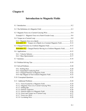
Chapter 8Introduction to Magnetic Fields8.1 Introduction. 8-28.2 The Definition of a Magnetic Field . 8-38.3 Magnetic Force on a Current-Carrying Wire. 8-4Example 8.1: Magnetic Force on a Semi-Circular Loop . 8-68.4 Torque on a Current Loop . 8-88.4.1 Magnetic force on a dipole . 8-11Animation 8.1: Torques on a Dipole in a Constant Magnetic Field. 8-128.5 Charged Particles in a Uniform Magnetic Field . 8-13Animation 8.2: Charged Particle Moving in a Uniform Magnetic Field. 8-158.6 Applications . 8-158.6.1 Velocity Selector. 8-168.6.2 Mass Spectrometer. 8-178.7 Summary. 8-188.8 Problem-Solving Tips . 8-198.9 Solved Problems . 8-208.9.18.9.28.9.38.9.4Rolling Rod. 8-20Suspended Conducting Rod. 8-21Charged Particles in Magnetic Field. 8-22Bar Magnet in Non-Uniform Magnetic Field . 8-238.10 Conceptual Questions . 8-248.11 Additional Problems . .8Force Exerted by a Magnetic Field. 8-24Magnetic Force on a Current Carrying Wire . 8-24Sliding Bar . 8-25Particle Trajectory. 8-26Particle Orbits in a Magnetic Field . 8-26Force and Torque on a Current Loop. 8-27Force on a Wire. 8-27Levitating Wire . 8-288-1
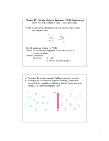
Introduction to Magnetic Fields8.1 IntroductionGWe have seen that a charged object produces an electric field E at all points in space. In aGsimilar manner, a bar magnet is a source of a magnetic field B . This can be readilydemonstrated by moving a compass near the magnet. The compass needle will line upalong the direction of the magnetic field produced by the magnet, as depicted in Figure8.1.1.Figure 8.1.1 Magnetic field produced by a bar magnetNotice that the bar magnet consists of two poles, which are designated as the north (N)and the south (S). Magnetic fields are strongest at the poles. The magnetic field linesleave from the north pole and enter the south pole. When holding two bar magnets closeto each other, the like poles will repel each other while the opposite poles attract (Figure8.1.2).Figure 8.1.2 Magnets attracting and repellingUnlike electric charges which can be isolated, the two magnetic poles always come in apair. When you break the bar magnet, two new bar magnets are obtained, each with anorth pole and a south pole (Figure 8.1.3). In other words, magnetic “monopoles” do notexist in isolation, although they are of theoretical interest.Figure 8.1.3 Magnetic monopoles do not exist in isolation8-2
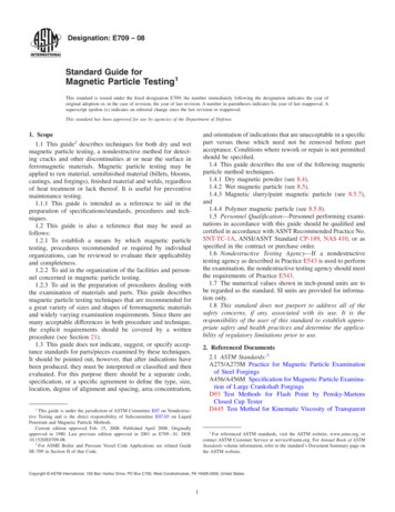
GGHow do we define the magnetic field B ? In the case of an electric field E , we havealready seen that the field is defined as the force per unit charge:GG FeE q(8.1.1)GHowever, due to the absence of magnetic monopoles, B must be defined in a differentway.8.2 The Definition of a Magnetic FieldTo define the magnetic field at a point, consider a particle of charge q and moving at aGvelocity v . Experimentally we have the following observations:G(1) The magnitude of the magnetic force FB exerted on the charged particle is proportionalto both v and q.GGG(2) The magnitude and direction of FB depends on v and B .GGGG(3) The magnetic force FB vanishes when v is parallel to B . However, when v makes anGGGGangle θ with B , the direction of FB is perpendicular to the plane formed by v and B ,Gand the magnitude of FB is proportional to sin θ .(4) When the sign of the charge of the particle is switched from positive to negative (orvice versa), the direction of the magnetic force also reverses.Figure 8.2.1 The direction of the magnetic forceThe above observations can be summarized with the following equation:GG GFB q v B(8.2.1)8-3
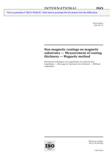
The above expression can be taken as the working definition of the magnetic field at aGpoint in space. The magnitude of FB is given byFB q vB sin θ(8.2.2)The SI unit of magnetic field is the tesla (T):1 tesla 1 T 1NewtonNN 1 1(Coulomb)(meter/second)C m/sA mGAnother commonly used non-SI unit for B is the gauss (G), where 1T 104 G .GGGNote that FB is always perpendicular to v and B , and cannot change the particle’s speedv (and thus the kinetic energy). In other words, magnetic force cannot speed up or slowGdown a charged particle. Consequently, FB can do no work on the particle:GGG G GG G GdW FB d s q ( v B) v dt q ( v v ) B dt 0(8.2.3)GThe direction of v , however, can be altered by the magnetic force, as we shall see below.8.3 Magnetic Force on a Current-Carrying WireWe have just seen that a charged particle moving through a magnetic field experiences aGmagnetic force FB . Since electric current consists of a collection of charged particles inmotion, when placed in a magnetic field, a current-carrying wire will also experience amagnetic force.Consider a long straight wire suspended in the region between the two magnetic poles.The magnetic field points out the page and is represented with dots ( ). It can be readilydemonstrated that when a downward current passes through, the wire is deflected to theleft. However, when the current is upward, the deflection is rightward, as shown in Figure8.3.1.Figure 8.3.1 Deflection of current-carrying wire by magnetic force8-4
To calculate the force exerted on the wire, consider a segment of wire of length A andcross-sectional area A, as shown in Figure 8.3.2. The magnetic field points into the page,and is represented with crosses ( X ).Figure 8.3.2 Magnetic force on a conducting wireGThe charges move at an average drift velocity v d . Since the total amount of charge in thissegment is Qtot q (nAA) , where n is the number of charges per unit volume, the totalmagnetic force on the segment isG GGG GG GFB Qtot v d B qnAA( v d B) I ( A B)(8.3.1)Gwhere I nqvd A , and A is a length vector with a magnitude A and directed along thedirection of the electric current.For a wire of arbitrary shape, the magnetic force can be obtained by summing over theforces acting on the small segments that make up the wire. Let the differential segment beGdenoted as d s (Figure 8.3.3).Figure 8.3.3 Current-carrying wire placed in a magnetic fieldThe magnetic force acting on the segment isGG Gd FB Id s B(8.3.2)GbG GFB I d s B(8.3.3)Thus, the total force isa8-5
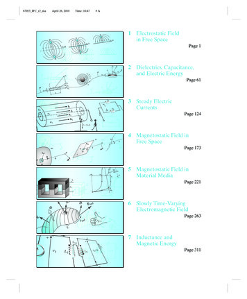
where a and b represent the endpoints of the wire.GAs an example, consider a curved wire carrying a current I in a uniform magnetic field B ,as shown in Figure 8.3.4.Figure 8.3.4 A curved wire carrying a current I.Using Eq. (8.3.3), the magnetic force on the wire is given byGFB I( )baG GG Gd s B I A B(8.3.4)Gwhere A is the length vector directed from a to b. However, if the wire forms a closedloop of arbitrary shape (Figure 8.3.5), then the force on the loop becomesGFB IG( v d Gs ) B(8.3.5)Figure 8.3.5 A closed loop carrying a current I in a uniform magnetic field.GSince the set of differential length elements d s form a closed polygon, and their vectorGGGsum is zero, i.e., v d s 0 . The net magnetic force on a closed loop is FB 0 .Example 8.1: Magnetic Force on a Semi-Circular LoopConsider a closed semi-circular loop lying in the xy plane carrying a current I in thecounterclockwise direction, as shown in Figure 8.3.6.8-6
Figure 8.3.6 Semi-circular loop carrying a current IA uniform magnetic field pointing in the y direction is applied. Find the magnetic forceacting on the straight segment and the semicircular arc.Solution:GGGLet B Bˆj and F1 and F2 the forces acting on the straight segment and the semicircularparts, respectively. Using Eq. (8.3.3) and noting that the length of the straight segment is2R, the magnetic force isGF1 I (2 R ˆi ) ( B ˆj) 2 IRB kˆwhere k̂ is directed out of the page.GGTo evaluate F2 , we first note that the differential length element d s on the semicircle canGbe written as d s ds θˆ Rdθ ( sin θ ˆi cos θ ˆj) . The force acting on the length elementGd s isGG GdF2 Id s B IR dθ ( sin θ ˆi cos θ ˆj) ( B ˆj) IBR sin θ dθ kˆGHere we see that dF2 points into the page. Integrating over the entire semi-circular arc,we haveGπF2 IBR kˆ sin θ dθ 2 IBR kˆ0Thus, the net force acting on the semi-circular wire isGG G GFnet F1 F2 0This is consistent from our previous claim that the net magnetic force acting on a closedcurrent-carrying loop must be zero.8-7
8.4 Torque on a Current LoopWhat happens when we place a rectangular loop carrying a current I in the xy plane andGswitch on a uniform magnetic field B B ˆi which runs parallel to the plane of the loop,as shown in Figure 8.4.1(a)?Figure 8.4.1 (a) A rectangular current loop placed in a uniform magnetic field. (b) Themagnetic forces acting on sides 2 and 4.From Eq. 8.4.1, we see the magnetic forces acting on sides 1 and 3 vanish because theGGGlength vectors A1 b ˆi and A 3 b ˆi are parallel and anti-parallel to B and their crossproducts vanish. On the other hand, the magnetic forces acting on segments 2 and 4 arenon-vanishing:G F2 I ( a ˆj) ( B ˆi ) IaB kˆ G F4 I (a ˆj) ( B ˆi ) IaB kˆ(8.4.1)GGwith F2 pointing out of the page and F4 into the page. Thus, the net force on therectangular loop isGG G G G GFnet F1 F2 F3 F4 0(8.4.2)GGas expected. Even though the net force on the loop vanishes, the forces F2 and F4 willproduce a torque which causes the loop to rotate about the y-axis (Figure 8.4.2). Thetorque with respect to the center of the loop isG b G b G b b τ ˆi F2 ˆi F4 ˆi IaB kˆ ˆi IaB kˆ 2 2 2 2 ( IabB IabB 2 2 ˆˆˆ j IabB j IAB j )()(8.4.3)8-8
where A ab represents the area of the loop and the positive sign indicates that therotation is clockwise about the y-axis. It is convenient to introduce the area vectorGA A nˆ where n̂ is a unit vector in the direction normal to the plane of the loop. Thedirection of the positive sense of n̂ is set by the conventional right-hand rule. In our case,we have n̂ kˆ . The above expression for torque can then be rewritten asG GGτ IA B(8.4.4)GNotice that the magnitude of the torque is at a maximum when B is parallel to the planeGof the loop (or perpendicular to A ).GConsider now the more general situation where the loop (or the area vector A ) makes anangle θ with respect to the magnetic field.Figure 8.4.2 Rotation of a rectangular current loopFrom Figure 8.4.2, the lever arms and can be expressed as:()G bGr2 sin θ ˆi cos θ kˆ r42(8.4.5)and the net torque becomesG GbG G G G Gτ r2 F2 r4 F4 2r2 F2 2 sin θ ˆi cos θ kˆ IaB kˆ2G G IabB sin θ ˆj IA B() ()(8.4.6)For a loop consisting of N turns, the magnitude of the toque isτ NIAB sin θ(8.4.7)GGThe quantity NIA is called the magnetic dipole moment µ :GGµ NI A(8.4.8)8-9
GFigure 8.4.3 Right-hand rule for determining the direction of µGGThe direction of µ is the same as the area vector A (perpendicular to the plane of theloop) and is determined by the right-hand rule (Figure 8.4.3). The SI unit for the magneticGdipole moment is ampere-meter2 (A m 2 ) . Using the expression for µ , the torque exertedon a current-carrying loop can be rewritten asG G Gτ µ B(8.4.9)G G GThe above equation is analogous to τ p E in Eq. (2.8.3), the torque exerted on anGGelectric dipole moment p in the presence of an electric field E . Recalling that theG Gpotential energy for an electric dipole is U p E [see Eq. (2.8.7)], a similar form isexpected for the magnetic case. The work done by an external agent to rotate themagnetic dipole from an angle θ 0 to θ is given byθθθ0θ0Wext τ dθ ′ ( µ B sin θ ′)dθ ′ µ B ( cos θ 0 cos θ ) U U U 0(8.4.10)Once again, Wext W , where W is the work done by the magnetic field. ChoosingU 0 0 at θ 0 π / 2 , the dipole in the presence of an external field then has a potentialenergy ofG GU µ B cos θ µ B(8.4.11)GGThe configuration is at a stable equilibrium when µ is aligned parallel to B , making U aGGminimum with U min µ B . On the other hand, when µ and B are anti-parallel,U max µ B is a maximum and the system is unstable.8-10
8.4.1 Magnetic force on a dipoleAs we have shown above, the force experienced by a current-carrying rectangular loop(i.e., a magnetic dipole) placed in a uniform magnetic field is zero. What happens if themagnetic field is non-uniform? In this case, there will be a net force acting on the dipole.GConsider the situation where a small dipole µ is placed along the symmetric axis of a barmagnet, as shown in Figure 8.4.4.Figure 8.4.4 A magnetic dipole near a bar magnet.The dipole experiences an attractive force by the bar magnet whose magnetic field is nonuniform in space. Thus, an external force must be applied to move the dipole to the right.The amount of force Fext exerted by an external agent to move the dipole by a distance x is given byFext x Wext U µ B( x x) µ B( x) µ[ B( x x) B ( x)](8.4.12)where we have used Eq. (8.4.11). For small x , the external force may be obtained asFext µ[ B( x x) B( x)]dB µdx x(8.4.13)which is a positive quantity since dB / dx 0 , i.e., the magnetic field decreases withincreasing x. This is precisely the force needed to overcome the attractive force due to thebar magnet. Thus, we haveFB µdB d G G (µ B)dx dx(8.4.14)GMore generally, the magnetic force experienced by a dipole µ placed in a non-uniformGmagnetic field B can be written asGG GFB (µ B)(8.4.15)where8-11
ˆ ˆ ˆi j k x y z(8.4.16)is the gradient operator.Animation 8.1: Torques on a Dipole in a Constant Magnetic Field“ To understand this point, we have to consider that a [compass] needlevibrates by gathering upon itself, because of it magnetic condition andpolarity, a certain amount of the lines of force, which would otherwisetraverse the space about it ”Michael Faraday [1855]Consider a magnetic dipole in a constant background field. Historically, we note thatFaraday understood the oscillations of a compass needle in exactly the way we describehere. We show in Figure 8.4.5 a magnetic dipole in a “dip needle” oscillating in themagnetic field of the Earth, at a latitude approximately the same as that of Boston. Themagnetic field of the Earth is predominantly downward and northward at these Northernlatitudes, as the visualization indicates.Figure 8.4.5 A magnetic dipole in the form of a dip needle oscillates in the magneticfield of the Earth.To explain what is going on in this visualization, suppose that the magnetic dipole vectoris initially along the direction of the earth’s field and rotating clockwise. As the dipolerotates, the magnetic field lines are compressed and stretched. The tensions and pressuresassociated with this field line stretching and compression results in an electromagnetictorque on the dipole that slows its clockwise rotation. Eventually the dipole comes to rest.But the counterclockwise torque still exists, and the dipole then starts to rotatecounterclockwise, passing back through being parallel to the Earth’s field again (wherethe torque goes to zero), and overshooting.As the dipole continues to rotate counterclockwise, the magnetic field lines are nowcompressed and stretched in the opposite sense. The electromagnetic torque has reversedsign, now slowing the dipole in its counterclockwise rotation. Eventually the dipole willcome to rest, start rotating clockwise once more, and pass back through being parallel to8-12
the field, as in the beginning. If there is no damping in the system, this motion continuesindefinitely.Figure 8.4.6 A magnetic dipole in the form of a dip needle rotates oscillates in themagnetic field of the Earth. We show the currents that produce the earth’s field in thisvisualization.What about the conservation of angular momentum in this situation? Figure 8.4.6 showsa global picture of the field lines of the dip needle and the field lines of the Earth, whichare generated deep in the core of the Earth. If you examine the stresses transmittedbetween the Earth and the dip needle in this visualization, you can convince yourself thatany clockwise torque on the dip needle is accompanied by a counterclockwise torque onthe currents producing the earth’s magnetic field. Angular momentum is conserved bythe exchange of equal and opposite amounts of angular momentum between the compassand the currents in the Earth’s core.8.5 Charged Particles in a Uniform Magnetic FieldIf a particle of mass m moves in a circle of radius r at a constant speed v, what acts on theparticle is a radial force of magnitude F mv 2 / r that always points toward the centerand is perpendicular to the velocity of the particle.GIn Section 8.2, we have also shown that the magnetic force FB always points in theGGdirection perpendicular to the velocity v of the charged particle and the magnetic field B .GGSince FB can do not work, it can only change the direction of v but not its magnitude.GWhat would happen if a charged particle moves through a uniform magnetic field B withGGits initial velocity v at a right angle to B ? For simplicity, let the charge be q and theGGdirection of B be into the page. It turns out that FB will play the role of a centripetalforce and the charged particle will move in a circular path in a counterclockwise direction,as shown in Figure 8.5.1.8-13
GGFigure 8.5.1 Path of a charge particle moving in a uniform B field with velocity vGinitially perpendicular to B .WithqvB mv 2r(8.5.1)the radius of the circle is found to ber mvqB(8.5.2)The period T (time required for one complete revolution) is given byT 2π r 2π mv 2π m vv qBqB(8.5.3)Similarly, the angular speed (cyclotron frequency) ω of the particle can be obtained asω 2π f v qB r m(8.5.4)If the initial velocity of the charged particle has a component parallel to the magneticGfield B , instead of a circle, the resulting trajectory will be a helical path, as shown inFigure 8.5.2:Figure 8.5.2 Helical path of a charged particle in an external magnetic field. The velocityGof the particle has a non-zero component along the direction of B .8-14
Animation 8.2: Charged Particle Moving in a Uniform Magnetic FieldFigure 8.5.3 shows a charge moving toward a region where the magnetic field isvertically upward. When the charge enters the region where the external magnetic field isnon-zero, it is deflected in a direction perpendicular to that field and to its velocity as itenters the field. This causes the charge to move in an arc that is a segment of a circle,until the charge exits the region where the external magnetic field in non-zero. We showin the animation the total magnetic field which is the sum of the external magnetic fieldand the magnetic field of the moving charge (to be shown in Chapter 9):G µ0 qvG rˆB 4π r 2(8.5.5)The bulging of that field on the side opposite the direction in which the particle is pushedis due to the buildup in magnetic pressure on that side. It is this pressure that causes thecharge to move in a circle.Figure 8.5.3 A charged particle moves in a magnetic field that is non-zero over the pieshaped region shown. The external field is upward.Finally, consider momentum conservation. The moving charge in the animation of Figure8.5.3 changes its direction of motion by ninety degrees over the course of the animation.How do we conserve momentum in this process? Momentum is conserved becausemomentum is transmitted by the field from the moving charge to the currents that aregenerating the constant external field. This is plausible given the field configurationshown in Figure 8.5.3. The magnetic field stress, which pushes the moving chargesideways, is accompanied by a tension pulling the current source in the opposite direction.To see this, look closely at the field stresses where the external field lines enter the regionwhere the currents that produce them are hidden, and remember that the magnetic fieldacts as if it were exerting a tension parallel to itself. The momentum loss by the movingcharge is transmitted to the hidden currents producing the constant field in this manner.8.6 ApplicationsThere are many applications involving charged particles moving through a uniformmagnetic field.8-15
8.6.1 Velocity SelectorGGIn the presence of both electric field E and magnetic field B , the total force on a chargedparticle isGG G GF q E v B()(8.6.1)This is known as the Lorentz force. By combining the two fields, particles which movewith a certain velocity can be selected. This was the principle used by J. J. Thomson tomeasure the charge-to-mass ratio of the electrons. In Figure 8.6.1 the schematic diagramof Thomson’s apparatus is depicted.Figure 8.6.1 Thomson’s apparatusThe electrons with charge q e and mass m are emitted from the cathode C and thenaccelerated toward slit A. Let the potential difference between A and C be VA VC V .The change in potential energy is equal to the external work done in accelerating theelectrons: U Wext q V e V . By energy conservation, the kinetic energy gainedis K U mv 2 / 2 . Thus, the speed of the electrons is given byv 2e Vm(8.6.2)If the electrons further pass through a region where there exists a downward uniformelectric field, the electrons, being negatively charged, will be deflected upward. However,if in addition to the electric field, a magnetic field directed into the page is also applied,G Gthen the electrons will experience an additional downward magnetic force e v B . Whenthe two forces exactly cancel, the electrons will move in a straight path. From Eq. 8.6.1,we see that when the condition for the cancellation of the two forces is given by eE evB ,which impliesv EB(8.6.3)In other words, only those particles with speed v E / B will be able to move in a straightline. Combining the two equations, we obtain8-16
eE2 m 2( V ) B 2(8.6.4)By measuring E , V and B , the charge-to-mass ratio can be readily determined. Themost precise measurement to date is e / m 1.758820174(71) 1011 C/kg .8.6.2 Mass SpectrometerVarious methods can be used to measure the mass of an atom. One possibility is throughthe use of a mass spectrometer. The basic feature of a Bainbridge mass spectrometer isillustrated in Figure 8.6.2. A particle carrying a charge q is first sent through a velocityselector.Figure 8.6.2 A Bainbridge mass spectrometerThe applied electric and magnetic fields satisfy the relation E vB so that the trajectoryof the particle is a straight line. Upon entering a region where a second magnetic fieldGB 0 pointing into the page has been applied, the particle will move in a circular path withradius r and eventually strike the photographic plate. Using Eq. 8.5.2, we haver mvqB0(8.6.5)Since v E / B, the mass of the particle can be written asm qB0 r qB0 Br vE(8.6.6)8-17
8.7 Summary GThe magnetic force acting on a charge q traveling at a velocity v in a magneticGfield B is given byGG GFB qv B GThe magnetic force acting on a wire of length A carrying a steady current I in aGmagnetic field B isG GGFB I A B GGThe magnetic force dFB generated by a small portion of current I of length d s inGa magnetic field B isGG GdFB I d s B GThe torque τ acting on a close loop of wire of area A carrying a current I in aGuniform magnetic field B isG GGτ IA BGwhere A is a vector which has a magnitude of A and a direction perpendicular tothe loop. The magnetic dipole moment of a closed loop of wire of area A carrying acurrent I is given byGGµ IA GThe torque exerted on a magnetic dipole µ placed in an external magnetic fieldGB isG G Gτ µ B The potential energy of a magnetic dipole placed in a magnetic field isG GU µ B8-18
If a particle of charge q and mass m enters a magnetic field of magnitude B with aGvelocity v perpendicular to the magnetic field lines, the radius of the circular paththat the particle follows is given byr mv q Band the angular speed of the particle isω q Bm8.8 Problem-Solving TipsGIn this Chapter, we have shown that in the presence of both magnetic field B and theGelectric field E , the total force acting on a moving particle with charge qG G GG G GGis F Fe FB q (E v B) , where v is the velocity of the particle. The direction ofGGGFB involves the cross product of v and B , based on the right-hand rule. In Cartesiancoordinates, the unit vectors are î , ĵ and k̂ which satisfy the following properties:ˆi ˆj kˆ , ˆj kˆ ˆi , kˆ ˆi ˆjˆj ˆi kˆ , kˆ ˆj ˆi , ˆi kˆ ˆjˆi ˆi ˆj ˆj kˆ kˆ 0GGFor v vx ˆi v y ˆj vz kˆ and B Bx ˆi By ˆj Bz kˆ , the cross product may be obtained asˆiGGv B vxBxˆjvyBykˆvz (v y Bz vz By )ˆi (vz Bx vx Bz )ˆj (vx By v y Bx )kˆBzGGIf only the magnetic field is present, and v is perpendicular to B , then the trajectory is acircle with a radius r mv / q B , and an angular speed ω q B / m .When dealing with a more complicated case, it is useful to work with individual forcecomponents. For example,Fx max qEx q(v y Bz vz By )8-19
8.9 Solved Problems8.9.1 Rolling RodA rod with a mass m and a radius R is mounted on two parallel rails of length a separatedby a distance A , as shown in the Figure 8.9.1. The rod carries a current I and rolls withoutGslipping along the rails which are placed in a uniform magnetic field B directed into thepage. If the rod is initially at rest, what is its speed as it leaves the rails?Figure 8.9.1 Rolling rod in uniform magnetic fieldSolution:Using the coordinate system shown on the right, themagnetic force acting on the rod is given byG GGFB I A B I (A ˆi ) ( B kˆ ) I AB ˆj(8.9.1)The total work done by the magnetic force on the rod as it moves through the region isGGW FB d s FB a ( I AB )a(8.9.2)By the work-energy theorem, W must be equal to the change in kinetic energy: K 1 2 1 2mv I ω22(8.9.3)where both translation and rolling are involved. Since the moment of inertia of the rod isgiven by I mR 2 / 2 , and the condition of rolling with slipping implies ω v / R , wehave21 2 1 mR 2 v 1 2 1 2 3 2I ABa mv mv mv mv22 2 R 244(8.9.4)8-20
Thus, the speed of the rod as it leaves the rails isv 8.9.24 I ABa3m(8.9.5)Suspended Conducting RodA conducting rod having a mass density λ kg/m is suspended by two flexible wires in aGuniform magnetic field B which points out of the page, as shown in Figure 8.9.2.Figure 8.9.2 Suspended conducting rod in uniform magnetic fieldIf the tension on the wires is zero, what are the magnitude and the direction of the currentin the rod?Solution:In order that the tension in the wires be zero, the magneticG GGforce FB I A B acting on the conductor must exactlyGcancel the downward gravitational force Fg mgkˆ .GGFor FB to point in the z-direction, we must have A A ˆj , i.e., the current flows to theleft, so thatG GGFB I A B I ( A ˆj) ( B ˆi ) I AB (ˆj ˆi ) I AB kˆ(8.9.6)The magnitude of the current can be obtain fromI AB mg(8.9.7)8-21
orI mg λ g BAB(8.9.8)8.9.3 Charged Particles in Magnetic FieldParticle A with charge q and mass mA and particle B with charge 2q and mass mB , areaccelerated from rest by a potential difference V , and subsequently deflected by auniform magnetic field into semicircular paths. The radii of the trajectories by particle Aand B are R and 2R, respectively. The direction of the magnetic field is perpendicular tothe velocity of the particle. What is their mass ratio?Solution:The kinetic energy gained by the charges is equal to1 2mv q V2(8.9.9)which yieldsv 2q Vm(8.9.10)The charges move in semicircles, since the magnetic force points radially inward andprovides the source of the centripetal force:mv 2 qvBr(8.9.11)The radius of the circle can be readily obtained as:r mv m 2q V 1 2m V qB qBmBq(8.9.12)which shows that r is proportional to (m / q )1/ 2 . The mass ratio can then be obtained fromrA (mA / q A )1/ 2 rB (mB / qB )1/ 2(mA / q )1/ 2R 2 R (mB / 2q )1/ 2(8.9.13)which givesmA
where is the length vector directed from a to b. However, if the wire forms a closed loop of arbitrary shape (Figure 8.3.5), then the force on the loop becomes G A FB Id( s) B G GG v (8.3.5) Figure 8.3.5 A closed loop carrying a current I in a uniform magnetic field. Since the set of differential length elements d s G