Transcription
Chapter NineRAY OPTICSAND OPTICALINSTRUMENTS9.1 INTRODUCTIONNature has endowed the human eye (retina) with the sensitivity to detectelectromagnetic waves within a small range of the electromagneticspectrum. Electromagnetic radiation belonging to this region of thespectrum (wavelength of about 400 nm to 750 nm) is called light. It ismainly through light and the sense of vision that we know and interpretthe world around us.There are two things that we can intuitively mention about light fromcommon experience. First, that it travels with enormous speed and second,that it travels in a straight line. It took some time for people to realise thatthe speed of light is finite and measurable. Its presently accepted valuein vacuum is c 2.99792458 108 m s–1. For many purposes, it sufficesto take c 3 108 m s–1. The speed of light in vacuum is the highestspeed attainable in nature.The intuitive notion that light travels in a straight line seems tocontradict what we have learnt in Chapter 8, that light is anelectromagnetic wave of wavelength belonging to the visible part of thespectrum. How to reconcile the two facts? The answer is that thewavelength of light is very small compared to the size of ordinary objectsthat we encounter commonly (generally of the order of a few cm or larger).In this situation, as you will learn in Chapter 10, a light wave can beconsidered to travel from one point to another, along a straight line joining
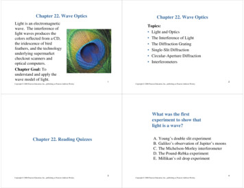
Physicsthem. The path is called a ray of light, and a bundle of such raysconstitutes a beam of light.In this chapter, we consider the phenomena of reflection, refractionand dispersion of light, using the ray picture of light. Using the basiclaws of reflection and refraction, we shall study the image formation byplane and spherical reflecting and refracting surfaces. We then go on todescribe the construction and working of some important opticalinstruments, including the human eye.PARTICLEMODEL OF LIGHTNewton’s fundamental contributions to mathematics, mechanics, and gravitation often blindus to his deep experimental and theoretical study of light. He made pioneering contributionsin the field of optics. He further developed the corpuscular model of light proposed byDescartes. It presumes that light energy is concentrated in tiny particles called corpuscles.He further assumed that corpuscles of light were massless elastic particles. With hisunderstanding of mechanics, he could come up with a simple model of reflection andrefraction. It is a common observation that a ball bouncing from a smooth plane surfaceobeys the laws of reflection. When this is an elastic collision, the magnitude of the velocityremains the same. As the surface is smooth, there is no force acting parallel to the surface,so the component of momentum in this direction also remains the same. Only the componentperpendicular to the surface, i.e., the normal component of the momentum, gets reversedin reflection. Newton argued that smooth surfaces like mirrors reflect the corpuscles in asimilar manner.In order to explain the phenomena of refraction, Newton postulated that the speed ofthe corpuscles was greater in water or glass than in air. However, later on it was discoveredthat the speed of light is less in water or glass than in air.In the field of optics, Newton – the experimenter, was greater than Newton – the theorist.He himself observed many phenomena, which were difficult to understand in terms ofparticle nature of light. For example, the colours observed due to a thin film of oil on water.Property of partial reflection of light is yet another such example. Everyone who has lookedinto the water in a pond sees image of the face in it, but also sees the bottom of the pond.Newton argued that some of the corpuscles, which fall on the water, get reflected and someget transmitted. But what property could distinguish these two kinds of corpuscles? Newtonhad to postulate some kind of unpredictable, chance phenomenon, which decided whetheran individual corpuscle would be reflected or not. In explaining other phenomena, however,the corpuscles were presumed to behave as if they are identical. Such a dilemma does notoccur in the wave picture of light. An incoming wave can be divided into two weaker wavesat the boundary between air and water.9.2 REFLECTION310OFLIGHTBYSPHERICAL MIRRORSWe are familiar with the laws of reflection. The angle of reflection (i.e., theangle between reflected ray and the normal to the reflecting surface orthe mirror) equals the angle of incidence (angle between incident ray andthe normal). Also that the incident ray, reflected ray and the normal tothe reflecting surface at the point of incidence lie in the same plane(Fig. 9.1). These laws are valid at each point on any reflecting surfacewhether plane or curved. However, we shall restrict our discussion to thespecial case of curved surfaces, that is, spherical surfaces. The normal in
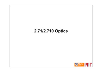
Ray Optics andOptical Instrumentsthis case is to be taken as normal to the tangentto surface at the point of incidence. That is, thenormal is along the radius, the line joining thecentre of curvature of the mirror to the point ofincidence.We have already studied that the geometriccentre of a spherical mirror is called its pole whilethat of a spherical lens is called its optical centre.The line joining the pole and the centre of curvatureof the spherical mirror is known as the principalaxis. In the case of spherical lenses, the principalaxis is the line joining the optical centre with itsprincipal focus as you will see later.FIGURE 9.1 The incident ray, reflected rayand the normal to the reflecting surface liein the same plane.9.2.1 Sign conventionTo derive the relevant formulae for reflection by spherical mirrors andrefraction by spherical lenses, we must first adopt a sign convention formeasuring distances. In this book, we shall follow the Cartesian signconvention. According to thisconvention, all distances are measuredfrom the pole of the mirror or the opticalcentre of the lens. The distancesmeasured in the same direction as theincident light are taken as positive andthose measured in the directionopposite to the direction of incidentlight are taken as negative (Fig. 9.2).The heights measured upwards withrespect to x-axis and normal to theprincipal axis (x-axis) of the mirror/lens are taken as positive (Fig. 9.2). Theheights measured downwards areFIGURE 9.2 The Cartesian Sign Convention.taken as negative.With a common accepted convention, it turns out that a single formulafor spherical mirrors and a single formula for spherical lenses can handleall different cases.9.2.2 Focal length of spherical mirrorsFigure 9.3 shows what happens when a parallel beam of light is incidenton (a) a concave mirror, and (b) a convex mirror. We assume that the raysare paraxial, i.e., they are incident at points close to the pole P of the mirrorand make small angles with the principal axis. The reflected rays convergeat a point F on the principal axis of a concave mirror [Fig. 9.3(a)].For a convex mirror, the reflected rays appear to diverge from a point Fon its principal axis [Fig. 9.3(b)]. The point F is called the principal focusof the mirror. If the parallel paraxial beam of light were incident, makingsome angle with the principal axis, the reflected rays would converge (orappear to diverge) from a point in a plane through F normal to the principalaxis. This is called the focal plane of the mirror [Fig. 9.3(c)].311
PhysicsFIGURE 9.3 Focus of a concave and convex mirror.The distance between the focus F and the pole P of the mirror is calledthe focal length of the mirror, denoted by f. We now show that f R/2,where R is the radius of curvature of the mirror. The geometryof reflection of an incident ray is shown in Fig. 9.4.Let C be the centre of curvature of the mirror. Consider aray parallel to the principal axis striking the mirror at M. ThenCM will be perpendicular to the mirror at M. Let θ be the angleof incidence, and MD be the perpendicular from M on theprincipal axis. Then, MCP θ and MFP 2θNow,MDMDand tan 2θ (9.1)CDFDFor small θ, which is true for paraxial rays, tanθ θ,tan 2θ 2θ. Therefore, Eq. (9.1) givestanθ FIGURE 9.4 Geometry ofreflection of an incident ray on(a) concave spherical mirror,and (b) convex spherical mirror.MDMD 2FDCDCDor, FD (9.2)2Now, for small θ, the point D is very close to the point P.Therefore, FD f and CD R. Equation (9.2) then givesf R/2(9.3)9.2.3 The mirror equation312If rays emanating from a point actually meet at another point afterreflection and/or refraction, that point is called the image of the firstpoint. The image is real if the rays actually converge to the point; it is
Ray Optics andOptical Instrumentsvirtual if the rays do not actually meet but appearto diverge from the point when producedbackwards. An image is thus a point-to-pointcorrespondence with the object establishedthrough reflection and/or refraction.In principle, we can take any two raysemanating from a point on an object, trace theirpaths, find their point of intersection and thus,obtain the image of the point due to reflection at aspherical mirror. In practice, however, it isconvenient to choose any two of the following rays:(i) The ray from the point which is parallel to theprincipal axis. The reflected ray goes throughFIGURE 9.5 Ray diagram for imagethe focus of the mirror.formation by a concave mirror.(ii) The ray passing through the centre ofcurvature of a concave mirror or appearing to pass through it for aconvex mirror. The reflected ray simply retraces the path.(iii) The ray passing through (or directed towards) the focus of the concavemirror or appearing to pass through (or directed towards) the focusof a convex mirror. The reflected ray is parallel to the principal axis.(iv) The ray incident at any angle at the pole. The reflected ray followslaws of reflection.Figure 9.5 shows the ray diagram considering three rays. It showsthe image A′B′ (in this case, real) of an object A B formed by a concavemirror. It does not mean that only three rays emanate from the point A.An infinite number of rays emanate from any source, in all directions.Thus, point A′ is image point of A if every ray originating at point A andfalling on the concave mirror after reflection passes through the point A′.We now derive the mirror equation or the relation between the objectdistance (u), image distance (v) and the focal length ( f ).From Fig. 9.5, the two right-angled triangles A′B′F and MPF aresimilar. (For paraxial rays, MP can be considered to be a straight lineperpendicular to CP.) Therefore,BAPMBFFPBA BF( PM AB)(9.4)BAFPSince APB A′PB′, the right angled triangles A′B′P and ABP arealso similar. Therefore,orBA B PB A BPComparing Eqs. (9.4) and (9.5), we get(9.5)B F B P – FP B P(9.6)FPFPBPEquation (9.6) is a relation involving magnitude of distances. We nowapply the sign convention. We note that light travels from the object tothe mirror MPN. Hence this is taken as the positive direction. To reach313
Physicsthe object AB, image A′B′ as well as the focus F from the pole P, we haveto travel opposite to the direction of incident light. Hence, all the threewill have negative signs. Thus,B′ P –v, FP –f, BP –uUsing these in Eq. (9.6), we get–v f–f–v–uv– fvfu1 11(9.7)v ufThis relation is known as the mirror equation.The size of the image relative to the size of the object is anotherimportant quantity to consider. We define linear magnification (m) as theratio of the height of the image (h′) to the height of the object (h):orh(9.8)hh and h′ will be taken positive or negative in accordance with the acceptedsign convention. In triangles A′B′P and ABP, we have,m BABPBABPWith the sign convention, this becomes–hhso that–v–uhv–(9.9)huWe have derived here the mirror equation, Eq. (9.7), and themagnification formula, Eq. (9.9), for the case of real, inverted image formedby a concave mirror. With the proper use of sign convention, these are,in fact, valid for all the cases of reflection by a spherical mirror (concaveor convex) whether the image formed is real or virtual. Figure 9.6 showsthe ray diagrams for virtual image formed by a concave and convex mirror.You should verify that Eqs. (9.7) and (9.9) are valid for these casesas well.m 314FIGURE 9.6 Image formation by (a) a concave mirror with object betweenP and F, and (b) a convex mirror.
Ray Optics andOptical InstrumentsExample 9.1 Suppose that the lower half of the concave mirror’sreflecting surface in Fig. 9.5 is covered with an opaque (non-reflective)material. What effect will this have on the image of an object placedin front of the mirror?EXAMPLE 9.1Solution You may think that the image will now show only half of theobject, but taking the laws of reflection to be true for all points of theremaining part of the mirror, the image will be that of the whole object.However, as the area of the reflecting surface has been reduced, theintensity of the image will be low (in this case, half).Example 9.2 A mobile phone lies along the principal axis of a concavemirror, as shown in Fig. 9.7. Show by suitable diagram, the formationof its image. Explain why the magnification is not uniform. Will thedistortion of image depend on the location of the phone with respectto the mirror?EXAMPLE 9.2FIGURE 9.7SolutionThe ray diagram for the formation of the image of the phone is shownin Fig. 9.7. The image of the part which is on the plane perpendicularto principal axis will be on the same plane. It will be of the same size,i.e., B′C BC. You can yourself realise why the image is distorted.Example 9.3 An object is placed at (i) 10 cm, (ii) 5 cm in front of aconcave mirror of radius of curvature 15 cm. Find the position, nature,and magnification of the image in each case.SolutionThe focal length f –15/2 cm –7.5 cm(i) The object distance u –10 cm. Then Eq. (9.7) gives1vor1– 10v 1– 7. 510 7.52 .5 – 30 cmv( 30)––3u( 10)The image is magnified, real and inverted.Also, magnification m –EXAMPLE 9.3The image is 30 cm from the mirror on the same side as the object.315
Physics(ii) The object distance u –5 cm. Then from Eq. (9.7),1v15v EXAMPLE 9.3or17.55 7 .57.5 – 515 cmThis image is formed at 15 cm behind the mirror. It is a virtual image.v15–3u( 5)The image is magnified, virtual and erect.Magnification m –Example 9.4 Suppose while sitting in a parked car, you notice ajogger approaching towards you in the side view mirror of R 2 m. Ifthe jogger is running at a speed of 5 m s–1, how fast the image of thejogger appear to move when the jogger is (a) 39 m, (b) 29 m, (c) 19 m,and (d) 9 m away.SolutionFrom the mirror equation, Eq. (9.7), we getvfuufFor convex mirror, since R 2 m, f 1 m. Then( 39) 1 39m39 140Since the jogger moves at a constant speed of 5 m s–1, after 1 s theposition of the image v (for u –39 5 –34) is (34/35 )m.The shift in the position of image in 1 s isfor u –39 m, vEXAMPLE 9.439 34 1365 136051m40 3514001400 280Therefore, the average speed of the image when the jogger is between39 m and 34 m from the mirror, is (1/280) m s–1Similarly, it can be seen that for u –29 m, –19 m and –9 m, thespeed with which the image appears to move is111m s –1 ,m s –1 andm s –1 , respectively.1506010Although the jogger has been moving with a constant speed, the speedof his/her image appears to increase substantially as he/she movescloser to the mirror. This phenomenon can be noticed by any personsitting in a stationary car or a bus. In case of moving vehicles, asimilar phenomenon could be observed if the vehicle in the rear ismoving closer with a constant speed.9.3 REFRACTION316When a beam of light encounters another transparent medium, a part oflight gets reflected back into the first medium while the rest enters theother. A ray of light represents a beam. The direction of propagation ofan obliquely incident ray of light that enters the other medium, changes
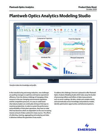
Ray Optics andOptical Instrumentsat the interface of the two media. Thisphenomenon is called refraction of light. Snellexperimentally obtained the following laws ofrefraction:(i) The incident ray, the refracted ray and thenormal to the interface at the point ofincidence, all lie in the same plane.(ii) The ratio of the sine of the angle of incidenceto the sine of angle of refraction is constant.Remember that the angles of incidence (i ) andrefraction (r ) are the angles that the incidentand its refracted ray make with the normal,respectively. We havesin isin rn 21(9.10)FIGURE 9.8 Refraction and reflection of light.where n 21 is a constant, called the refractive index of the second mediumwith respect to the first medium. Equation (9.10) is the well-known Snell’slaw of refraction. We note that n 21 is a characteristic of the pair of media(and also depends on the wavelength of light), but is independent of theangle of incidence.From Eq. (9.10), if n 21 1, r i , i.e., the refracted ray bends towardsthe normal. In such a case medium 2 is said to be optically denser (ordenser, in short) than medium 1. On the other hand, if n 21 1, r i, therefracted ray bends away from the normal. This is the case when incidentray in a denser medium refracts into a rarer medium.Note: Optical density should not be confused with mass density,which is mass per unit volume. It is possible that mass density ofan optically denser medium may be less than that of an opticallyrarer medium (optical density is the ratio of the speed of light intwo media). For example, turpentine and water. Mass density ofturpentine is less than that of water but its optical density is higher.If n 21 is the refractive index of medium 2with respect to medium 1 and n12 the refractiveindex of medium 1 with respect to medium 2,then it should be clear thatn121n 21(9.11)It also follows that if n 32 is the refractiveindex of medium 3 with respect to medium 2then n 32 n 31 n 12, where n 31 is the refractiveindex of medium 3 with respect to medium 1.FIGURE 9.9 Lateral shift of a ray refractedSome elementary results based on the lawsthrough a parallel-sided slab.of refraction follow immediately. For arectangular slab, refraction takes place at twointerfaces (air-glass and glass-air). It is easily seen from Fig. 9.9 that317r2 i1, i.e., the emergent ray is parallel to the incident ray—there is no
PhysicsFIGURE 9.10 Apparent depth for(a) normal, and (b) oblique viewing.deviation, but it does suffer lateral displacement/shift with respect to the incident ray. Another familiarobservation is that the bottom of a tank filled withwater appears to be raised (Fig. 9.10). For viewingnear the normal direction, it can be shown that theapparent depth, (h1) is real depth (h 2) divided bythe refractive index of the medium (water).The refraction of light through the atmosphereis responsible for many interesting phenomena. Forexample, the sun is visible a little before the actualsunrise and until a little after the actual sunsetdue to refraction of light through the atmosphere(Fig. 9.11). By actual sunrise we mean the actualcrossing of the horizon by the sun. Figure 9.11shows the actual and apparent positions of the sunwith respect to the horizon. The figure is highlyexaggerated to show the effect. The refractive indexof air with respect to vacuum is 1.00029. Due tothis, the apparent shift in the direction of the sunis by about half a degree and the correspondingtime difference between actual sunset and apparentsunset is about 2 minutes (see Example 9.5). Theapparent flattening (oval shape) of the sun at sunsetand sunrise is also due to the same phenomenon.318EXAMPLE 9.5FIGURE 9.11 Advance sunrise and delayed sunset due toatmospheric refraction.Example 9.5 The earth takes 24 h to rotate once about its axis. Howmuch time does the sun take to shift by 1º when viewed fromthe earth?SolutionTime taken for 360 shift 24 hTime taken for 1 shift 24/360 h 4 min.
Ray Optics andOptical InstrumentsTHEDROWNING CHILD, LIFEGUARD ANDSNELL’SLAWConsider a rectangular swimming pool PQSR; see figure here. A lifeguard sitting at Goutside the pool notices a child drowning at a point C. The guard wants to reach thechild in the shortest possible time. Let SR be theside of the pool between G and C. Should he/shetake a straight line path GAC between G and C orGBC in which the path BC in water would be theshortest, or some other path GXC? The guard knowsthat his/her running speed v1 on ground is higherthan his/her swimming speed v2.Suppose the guard enters water at X. Let GX l1and XC l 2. Then the time taken to reach from G toC would betl1v1l2v2To make this time minimum, one has todifferentiate it (with respect to the coordinate of X ) and find the point X when t is aminimum. On doing all this algebra (which we skip here), we find that the guard shouldenter water at a point where Snell’s law is satisfied. To understand this, draw aperpendicular LM to side SR at X. Let GXM i and CXL r. Then it can be seen that tis minimum whensin isin rv1v2In the case of light v1/v2, the ratio of the velocity of light in vacuum to that in themedium, is the refractive index n of the medium.In short, whether it is a wave or a particle or a human being, whenever two mediumsand two velocities are involved, one must follow Snell’s law if one wants to take theshortest time.9.4 TOTAL INTERNAL REFLECTIONWhen light travels from an optically denser medium to a rarer mediumat the interface, it is partly reflected back into the same medium andpartly refracted to the second medium. This reflection is called the internalreflection.When a ray of light enters from a denser medium to a rarer medium,it bends away from the normal, for example, the ray AO1 B in Fig. 9.12.The incident ray AO1 is partially reflected (O1C) and partially transmitted(O1B) or refracted, the angle of refraction (r ) being larger than the angle ofincidence (i ). As the angle of incidence increases, so does the angle ofrefraction, till for the ray AO3, the angle of refraction is π/2. The refractedray is bent so much away from the normal that it grazes the surface atthe interface between the two media. This is shown by the ray AO3 D inFig. 9.12. If the angle of incidence is increased still further (e.g., the rayAO4), refraction is not possible, and the incident ray is totally reflected.319
PhysicsThis is called total internal reflection. Whenlight gets reflected by a surface, normallysome fraction of it gets transmitted. Thereflected ray, therefore, is always less intensethan the incident ray, howsoever smooth thereflecting surface may be. In total internalreflection, on the other hand, notransmission of light takes place.The angle of incidence corresponding toan angle of refraction 90º, say AO3N, iscalled the critical angle (ic ) for the given pairof media. We see from Snell’s law [Eq. (9.10)]FIGURE 9.12 Refraction and internal reflectionof rays from a point A in the denser mediumthat if the relative refractive index is less(water) incident at different angles at the interface than one then, since the maximum valuewith a rarer medium (air).of sin r is unity, there is an upper limitto the value of sin i for which the law can be satisfied, that is, i icsuch thatsin ic n 21(9.12)For values of i larger than ic, Snell’s law of refraction cannot besatisfied, and hence no refraction is possible.The refractive index of denser medium 1 with respect to rarer medium2 will be n12 1/sin ic. Some typical critical angles are listed in Table 9.1.TABLE 9.1 CRITICAL ANGLE OF SOME TRANSPARENT MEDIA WITH RESPECT TO AIRSubstance mediumRefractive indexCritical angleWater1.3348.75 Crown glass1.5241.14 Dense flint glass1.6237.31 Diamond2.4224.41 A demonstration for total internal reflection320All optical phenomena can be demonstrated very easily with the use of alaser torch or pointer, which is easily available nowadays. Take a glassbeaker with clear water in it. Stir the water a few times with a piece ofsoap, so that it becomes a little turbid. Take a laser pointer and shine itsbeam through the turbid water. You will find that the path of the beaminside the water shines brightly.Shine the beam from below the beaker such that it strikes at theupper water surface at the other end. Do you find that it undergoes partialreflection (which is seen as a spot on the table below) and partial refraction[which comes out in the air and is seen as a spot on the roof; Fig. 9.13(a)]?Now direct the laser beam from one side of the beaker such that it strikesthe upper surface of water more obliquely [Fig. 9.13(b)]. Adjust thedirection of laser beam until you find the angle for which the refraction
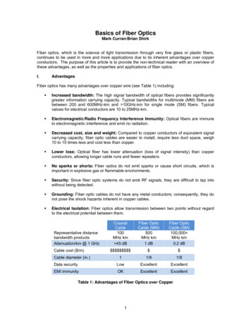
Ray Optics andOptical Instrumentsabove the water surface is totally absent and the beam is totally reflectedback to water. This is total internal reflection at its simplest.Pour this water in a long test tube and shine the laser light from top,as shown in Fig. 9.13(c). Adjust the direction of the laser beam such thatit is totally internally reflected every time it strikes the walls of the tube.This is similar to what happens in optical fibres.Take care not to look into the laser beam directly and not to point itat anybody’s face.9.4.1 Total internal reflection in nature andits technological applications(i) Mirage: On hot summer days, the air near the ground becomes hotterthan the air at higher levels. The refractive index of air increases withits density. Hotter air is less dense, and has smaller refractive indexthan the cooler air. If the air currents are small, that is, the air is still,the optical density at different layers of air increases with height. As aresult, light from a tall object such as a tree, passes through a mediumwhose refractive index decreases towards the ground. Thus, a ray oflight from such an object successively bends away from the normaland undergoes total internal reflection, if the angle of incidence forthe air near the ground exceeds the critical angle. This is shown inFig. 9.14(b). To a distant observer, the light appears to be comingFIGURE 9.13from somewhere below the ground. The observer naturally assumesObserving totalthat light is being reflected from the ground, say, by a pool of water internal reflection innear the tall object. Such inverted images of distant tall objects causewater with a laseran optical illusion to the observer. This phenomenon is called mirage. beam (refraction dueto glass of beakerThis type of mirage is especially common in hot deserts. Some of youneglectedbeing verymight have noticed that while moving in a bus or a car during a hotthin).summer day, a distant patch of road, especially on a highway, appearsto be wet. But, you do not find any evidence of wetness when youreach that spot. This is also due to mirage.FIGURE 9.14 (a) A tree is seen by an observer at its place when the air above the ground isat uniform temperature, (b) When the layers of air close to the ground have varyingtemperature with hottest layers near the ground, light from a distant tree mayundergo total internal reflection, and the apparent image of the tree may create321an illusion to the observer that the tree is near a pool of water.
Physics(ii) Diamond : Diamonds are known for theirspectacular brilliance. Their brillianceis mainly due to the total internalreflection of light inside them. The criticalangle for diamond-air interface ( 24.4 )is very small, therefore once light entersa diamond, it is very likely to undergototal internal reflection inside it.Diamonds found in nature rarely exhibitthe brilliance for which they are known.It is the technical skill of a diamondcutter which makes diamonds tosparkle so brilliantly. By cutting thediamond suitably, multiple totalinternal reflections can be madeto occur.(iii) Prism : Prisms designed to bend light byFIGURE 9.15 Prisms designed to bend rays by90º or by 180º make use of total internal90º and 180º or to invert image without changingreflection [Fig. 9.15(a) and (b)]. Such aits size make use of total internal reflection.prism is also used to invert imageswithout changing their size [Fig. 9.15(c)].In the first two cases, the critical angle ic for the material of the prismmust be less than 45º. We see from Table 9.1 that this is true for bothcrown glass and dense flint glass.(iv) Optical fibres: Now-a-days optical fibres are extensively used fortransmitting audio and video signals through long distances. Opticalfibres too make use of the phenomenon of total internal reflection.Optical fibres are fabricated with high quality composite glass/quartzfibres. Each fibre consists of a core and cladding. The refractive indexof the material of the core is higher than that of the cladding.When a signal in the form of light isdirected at one end of the fibre at a suitableangle, it undergoes repeated total internalreflections along the length of the fibre andfinally comes out at the other end (Fig. 9.16).Since light undergoes total internal reflectionat each stage, there is no appreciable loss inthe intensity of the light signal. Optical fibresFIGURE 9.16 Light undergoes successive totalare fabricated such that light reflected at oneinternal reflections as it moves through anside of inner surface strikes the other at anoptical fibre.angle larger than the critical angle. Even if thefibre is bent, light can easily travel along itslength. Thus, an optical fibre can be used to act as an optical pipe.A bundle of optical fibres can be put to several uses. Optical fibresare extensively used for transmitting and receiving electrical signals whichare converted to light by suitable transducers. Obviously, optical fibrescan also be used for transmission of optical signals. For example, theseare used as a ‘light pipe’ to facilitate visual examination of internal organs322like esophagus, stomach and intestines. You might have seen a commonly
Ray Optics andOptical Instrumentsavailable decorative lamp with fine plastic fibres with their free endsforming a fountain like
wavelength of light is very small compared to the size of ordinary objects that we encounter commonly (generally of the order of a few cm or larger). . (or directed towards) the focus of a convex mirror. The reflected ray is parallel to the principal axis. (iv) The ray incident at any angle at the pole. The reflected ray follows