Transcription
Chapter 5: X-Ray ProductionSlide set of 121 slides based on the chapter authored byR. Nowotnyof the IAEA publication (ISBN 978-92-0-131010-1):Diagnostic Radiology Physics:A Handbook for Teachers and StudentsObjective:To familiarize the student with the principles of X ray productionand the characterization of the radiation output of X ray tubes.Slide set preparedby K.P. Maherfollowing initial work byS. EdyveanIAEAInternational Atomic Energy Agency
CHAPTER 5TABLE OF CONTENTS5.1 Introduction5.2 Fundamentals of X Ray Production5.3 X Ray Tubes5.4 Energizing & Controlling the X Ray Tube5.5 X Ray Tube & Generator Ratings5.6 Collimation & Filtration5.7 Factors Influencing X Ray Spectra & Output5.8 FiltrationBibliographyIAEADiagnostic Radiology Physics: a Handbook for Teachers and Students – chapter 5, 2
CHAPTER 55.15.2IntroductionFundamentals of X Ray Production5.2.15.2.25.2.35.3TABLE OF CONTENTSBremsstrahlungCharacteristic RadiationX Ray SpectrumX Ray Tubes5.3.15.3.25.3.3IAEAComponents of the X Ray 55.3.3.6Choice of materialLine-Focus principle (Anode angle)Stationary and rotating anodesThermal propertiesTube envelopeTube housingDiagnostic Radiology Physics: a Handbook for Teachers and Students – chapter 5, 3
CHAPTER 55.4TABLE OF CONTENTSEnergizing & Controlling the X-Ray Tube5.4.15.4.2Filament CircuitGenerating the Tube .4.35.4.45.5Single-phase generatorsThree-phase generatorsHigh-frequency generatorsCapacitive discharge generatorsConstant voltage generatorsComparison of generator technologiesExposure Timing (AEC)Falling LoadX-Ray Tube & Generator Ratings5.5.15.5.2X Ray TubeTube HousingIAEADiagnostic Radiology Physics: a Handbook for Teachers and Students – chapter 5, 4
CHAPTER 55.6Collimation & Filtration5.6.15.6.25.6.35.6.45.7TABLE OF CONTENTSCollimator & Light FieldInherent FiltrationAdded FiltrationCompensation FiltersFactors Influencing X Ray Spectra & Output5.7.15.7.25.7.35.7.4Quantities Describing X Ray OutputTube Voltage & CurrentTube Voltage RippleAnode Angle5.8 FiltrationBibliographyIAEADiagnostic Radiology Physics: a Handbook for Teachers and Students – chapter 5, 5
5.1 INTRODUCTIONBasis of Radiological ImagingThe differential absorption of X rays in tissues and organs, due to theiratomic compositionX-Ray ProductionPrinciples have remained the same since their discovery howevermany design refinements have been introducedThis ChapterOutlines the principles of X ray production and characterizes theradiation output of XRTsIAEADiagnostic Radiology Physics: a Handbook for Teachers and Students – chapter 5, 6
5.2 FUNDAMENTALS OF X-RAY PRODUCTIONThe Production of X Rays involves the bombardment of athick target with energetic electronsElectrons undergo a complex sequence of collisions andscattering processes during the slowing down process whichresults in the production ofBremsstrahlung andCharacteristic RadiationA Simplified treatment of this process, based on classicaltheory, is provided in this sectionIAEADiagnostic Radiology Physics: a Handbook for Teachers and Students – chapter 5, 7
5.2 FUNDAMENTALS OF X-RAY PRODUCTION5.2.1 BremsstrahlungEnergetic Electrons are mostly slowed down in matter by:Collisions andExcitation interactionsIf an electron comes close to an atomic Nucleus the attractiveCoulomb forces causes a change of the electron’s trajectoryAn accelerated electron or an electron changing its directionemits electromagnetic radiation and given the nameBremsstrahlungIAEA(braking radiation)Diagnostic Radiology Physics: a Handbook for Teachers and Students – chapter 5, 8
5.2 FUNDAMENTALS OF X-RAY PRODUCTION5.2.1 BremsstrahlungThe energy of the emitted photon is subtracted from the kineticenergy of the electronThe Energy of the Bremsstrahlung photon depends on theAttractive Coulomb forces and hence on theDistance of the electron from the nucleusIAEADiagnostic Radiology Physics: a Handbook for Teachers and Students – chapter 5, 9
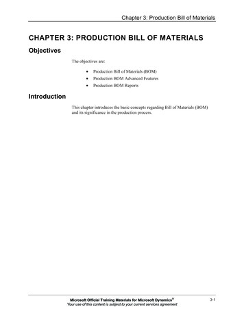
5.2 FUNDAMENTALS OF X-RAY PRODUCTION5.2.1 BremsstrahlungClassical TheoryConsider that electronbombardment of a thin targetyields a constant energy fluence(Ψ) from zero up to the initialelectron kinetic energy (T)IAEADiagnostic Radiology Physics: a Handbook for Teachers and Students – chapter 5, 10
5.2 FUNDAMENTALS OF X-RAY PRODUCTION5.2.1 BremsstrahlungA thick target can be thought ofas a sandwich of many thin targetlayers each producing arectangular distribution of energyfluenceThe superposition of all theserectangular distributions forms atriangular energy fluencedistribution for a thick target, theThe ideal spectrum does notinclude any attenuation effectsIdeal SpectrumIAEADiagnostic Radiology Physics: a Handbook for Teachers and Students – chapter 5, 11
5.2 FUNDAMENTALS OF X-RAY PRODUCTION5.2.1 BremsstrahlungAccording to this modelAn increase in electron energy increases the number ofthin layers each radiating X raysThe triangular area grows proportional to the square ofthe electron energyTherefore, the Radiation Output of an XRT isproportional to U2U: tube voltagerelationship holds if spectral changes due to attenuationand emission of characteristic radiation are ignoredIAEADiagnostic Radiology Physics: a Handbook for Teachers and Students – chapter 5, 12
5.2 FUNDAMENTALS OF X-RAY PRODUCTION5.2.2 Characteristic RadiationA Fast Electron colliding with an electron of an atomic shellcould knock out the electron once its KE exceeds the bindingenergy of the electron in that shellThe binding energy is Highest in the most innerK-shell and decreases for the outer shells (L, M, .)The Scattered primary electron carries away the difference ofkinetic energy and binding energyThe vacancy in the shell is then filled with an electron from anouter shell accompanied by the emission of an X Ray Photonwith an energy equivalent to the Difference in bindingenergies of the shells involvedIAEADiagnostic Radiology Physics: a Handbook for Teachers and Students – chapter 5, 13
5.2 FUNDAMENTALS OF X-RAY PRODUCTION5.2.2 Characteristic RadiationFor each element binding energies and the Monoenergeticradiation resulting from such interactions, are unique andCharacteristic for that elementBinding energy, keVEnergies of characteristic X rays, keVElementL-shellKa1Ka2Kb1Kb2W12.10/11.54/10.21 hell20.0023.22Instead of characteristic radiation the energy available could betransferred to an electron which is ejected from the shell (AugerElectron) - production probability decreases with ZIAEADiagnostic Radiology Physics: a Handbook for Teachers and Students – chapter 5, 14
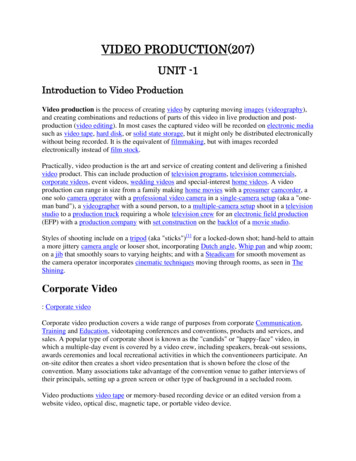
5.2 FUNDAMENTALS OF X-RAY PRODUCTION5.2.3 X-ray Spectruma) Ideal Bremsstrahlungspectrum for a tungstenanode (tube voltage 90 kV)b) An Actual spectrum atthe beam exit port withcharacteristic X rays(anode angle: 20 , inherentfiltration: 1 mm Be)c) The spectrum Filteredwith an equivalent of2.5 mm AlIAEADiagnostic Radiology Physics: a Handbook for Teachers and Students – chapter 5, 15
5.2 FUNDAMENTALS OF X-RAY PRODUCTION5.2.3 X-ray SpectrumThe electrons are slowed down and stopped in the Targetwithin a range of a few tens of µmX rays are not generated at the surface but within the targetresulting in Attenuation of the X ray beamSelf-Filtration appears most prominent at the low-energy endof the spectrumCharacteristic Radiation shows up if the kinetic energy of theelectron exceeds the binding energiesIAEADiagnostic Radiology Physics: a Handbook for Teachers and Students – chapter 5, 16
5.2 FUNDAMENTALS OF X-RAY PRODUCTION5.2.3 X-ray SpectrumL-Radiation is totally absorbed by a typical filtration of 2.5mm AlThe K-Edge in the photon attenuation of tungsten can benoticed as a drop of the continuum at the binding energy of69.5 keVFor tungsten targets the fraction of K-radiation contributingto the total energy fluence is 10% for 150 kV tube voltageIAEADiagnostic Radiology Physics: a Handbook for Teachers and Students – chapter 5, 17
5.2 FUNDAMENTALS OF X-RAY PRODUCTION5.2.3 X-ray SpectrumThe Radiative Mass Stopping Power of electrons isproportional to Z²Integration along the electron path gives the total X rayenergy fluence asΨ Z·I·U²where I: electron current and U: tube voltageIf a high Bremsstrahlung yield is required, metals with high Zare preferableTungsten (Z 74) is commonly chosenas it also withstands high temperatures(2757 C at 1.3·10-2 Pa vapour pressure)IAEADiagnostic Radiology Physics: a Handbook for Teachers and Students – chapter 5, 18
5.2 FUNDAMENTALS OF X-RAY PRODUCTION5.2.3 X-ray SpectrumEfficiency for the conversion of electrical power toBremsstrahlung radiation is proportional to U·ZAt 100 kV the efficiency is as low as 0.8%This is the cause for most of the technical problems in thedesign of XRTs as practically all electrical power applied inthe acceleration of electrons is converted to HeatIAEADiagnostic Radiology Physics: a Handbook for Teachers and Students – chapter 5, 19
5.2 FUNDAMENTALS OF X-RAY PRODUCTION5.2.3 X-ray SpectrumThe ideal spectrum appears triangular with the EnergyFluence taken as the quantity describing the spectral intensityThe Photon Fluence is a more practical quantity forcalculations using spectral data and is therefore used in thefollowing sectionsMore refined models for the generation of X ray spectra havebeen developed using Monte Carlo methodsFor practical purposes a Semi Empirical approach givessatisfactory results, useful in simulationsIAEADiagnostic Radiology Physics: a Handbook for Teachers and Students – chapter 5, 20
5.3 X-RAY TUBES5.3.1 Components of the X Ray TubeThe production of both Bremsstrahlung and CharacteristicRadiation requires energetic electrons hitting a targetPrinciple components of an Xray tube are an ElectronSource from a heated tungstenfilament with a focusing cupserving as the tube Cathode,an Anode or Target and aTube Envelope to maintain aninterior vacuumIAEADiagnostic Radiology Physics: a Handbook for Teachers and Students – chapter 5, 21
5.3 X-RAY TUBES5.3.1 Components of the X Ray TubeThe Filament is heated by a current that controls thethermionic emission of electrons, which in turn determines thenumber of electrons flowing from cathode to anode (Tube orAnode Current)e.g. 10 mA in fluoroscopy and 100 to 1000 mA in single exposuresThe accelerating Potential Difference applied betweencathode and anode controls both X ray energy and yielde.g. 40 to 150 kV for general diagnostic radiology and 25 to 40 kV in mammographyThus Two main circuits operate within the XRT:Filament circuitTube voltage circuitIAEADiagnostic Radiology Physics: a Handbook for Teachers and Students – chapter 5, 22
5.3 X-RAY TUBES5.3.2 CathodeThe Arrangement of the filament, the focusing cup, the anodesurface and the tube voltage generates an electric fieldaccelerating the electrons towards the focal spot at the anodeThe typicalBimodaldistribution of thecurrent densitycan be seen in apinhole image ofthe focusThe effect of anUnbiasedfocusing cup onthe electric fieldand electrontrajectoriesNumbers indicate potentialdifference near the cup in kVIAEADiagnostic Radiology Physics: a Handbook for Teachers and Students – chapter 5, 23
5.3 X-RAY TUBES5.3.2 CathodeBiasing the focusing cup leads to a compression ofthe trajectories giving a smaller focusWith an increasing negative biasvoltage at the focusing cup the focussize will decrease and finally theelectron current will be pinched OffEffect is sometimes used toelectronically control the focus sizeor for a fast switching of the anodecurrent (Grid Controlled Tubes)when short radiation pulses arerequired as in pulsed fluoroscopyNumbers indicate potential differencenear the cup in kVIAEADiagnostic Radiology Physics: a Handbook for Teachers and Students – chapter 5, 24
5.3 X-RAY TUBES5.3.2 CathodeThe Spiral-Wound filament is typically made from tungstenwire of 0.2 to 0.3 mm diameter and operates at around 2700o KTo minimise the Evaporation of tungsten from the hot surface,the filament temperature is kept at a lower level except duringexposure when it is raised to operational levelsThermionic Emission of electrons increases with temperature(Richardson’s law) and produces a cloud of electrons (SpaceCharge) enclosing the filamentIAEADiagnostic Radiology Physics: a Handbook for Teachers and Students – chapter 5, 25
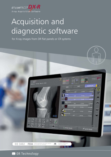
5.3 X-RAY TUBES5.3.2 CathodeSpace Charge shields the filament from the anode voltageAnode current IA vs.filament current If forvarious anode voltages UAshowing space-chargelimited anode currents forthe lower tube voltagesIAEADiagnostic Radiology Physics: a Handbook for Teachers and Students – chapter 5, 26
5.3 X-RAY TUBES5.3.2 CathodeFor high anode voltages all electrons boiled off the filamentare accelerated to the anode giving an anode current fairlyindependent of tube voltage (saturation current)Tube current IA vs. tubevoltage UA depending onfilament current IfNote: current saturation occurs forthe lower filament currentsIAEADiagnostic Radiology Physics: a Handbook for Teachers and Students – chapter 5, 27
5.3 X-RAY TUBES5.3.3 AnodeChoice of MaterialFor common radiographic applications a high Bremsstrahlungyield is mandatory requiring materials with high atomicnumbers (Z)Additionally, due to the low efficiency of X ray production it isalso essential that the thermal properties such as MaximumUseful Temperature determined by melting point and vapourpressure, heat conduction, specific heat and density are alsoconsideredTungsten (Z 74) is the optimum choiceIAEADiagnostic Radiology Physics: a Handbook for Teachers and Students – chapter 5, 28
5.3 X-RAY TUBES5.3.3 AnodeChoice of MaterialFor Mammography other anode materials such asmolybdenum (Z 42) and rhodium (Z 45) are frequently usedFor such anodes X ray spectra show less contribution byBremsstrahlung but rather dominant Characteristic X rays ofthe anode materialsAllows a more satisfactory Optimizationof image quality and patient doseIn Digital Mammography these advantages are lesssignificant and some manufacturers prefer tungsten anodesIAEADiagnostic Radiology Physics: a Handbook for Teachers and Students – chapter 5, 29
5.3 X-RAY TUBES5.3.3 AnodeLine-Focus Principle (Anode Angle)For measurement purposes the Focal Spot Size is definedalong the central beam projectionFor the sake of high anode currents the Area of the anode hitby the electrons should be as large as possible to keep powerdensity within acceptable limitsTo balance the need for large heat dissipation with that of asmall focal spot size the Line-Focus Principle is usedIAEADiagnostic Radiology Physics: a Handbook for Teachers and Students – chapter 5, 30
5.3 X-RAY TUBES5.3.3 AnodeLine-Focus Principle (Anode Angle)(a) Line Focus Principle:the length of the filamentappears shortened in thebeam direction(b) Graphic representation of the focalspot shape at different locations in theradiation field (anode angle 20 )IAEADiagnostic Radiology Physics: a Handbook for Teachers and Students – chapter 5, 31
5.3 X-RAY TUBES5.3.3 AnodeLine-Focus Principle (Anode Angle)The anode is Inclined to the tube axis typically with theCentral Ray of the X ray field perpendicular to the tube axisThe electrons hit the anode in the electronic focus largelydetermined by the Length of the cathode filamentThe electronic focus appears shortened in beam direction bysin θ as the Effective FocusAnode angles in diagnostic tubesrange from 6-22 depending on their taskwith 10-16 used for general purpose tubesIAEADiagnostic Radiology Physics: a Handbook for Teachers and Students – chapter 5, 32
5.3 X-RAY TUBES5.3.3 AnodeLine-Focus Principle (Anode Angle)The Radial Dimension of the focus size is given by thefilament coil diameter and the action of the focusing cupThe Size of the focal spot of an XRT is given for the centralbeam in the X ray field running Perpendicular to the electronbeam or the tube axisThe Actual focal spot size depends on the position within thefield of view increasing from the anode side of the tube to thecathodeIAEADiagnostic Radiology Physics: a Handbook for Teachers and Students – chapter 5, 33
5.3 X-RAY TUBES5.3.3 AnodeLine-Focus Principle (Anode Angle)The Reduction of anode angles to achieve smaller effectivefocus sizes is limited by the size of the field of view required asthe X ray beam is Cut Off by the anodeA further limit is given by the Heel EffectHere the X rays produced at Depth within the anode suffersome absorption losses according to the distance passed inthe anode materialIAEADiagnostic Radiology Physics: a Handbook for Teachers and Students – chapter 5, 34
5.3 X-RAY TUBES5.3.3 AnodeLine-Focus Principle (Anode Angle)For X rays emerging near the anode side of the X ray field thelosses are higher resulting in an Inhomogeneous X rayintensity across the beam(a) Absorption of X rays at thecathode side of the X ray field(a1) is less than at the anodeside (a2)(b) The steep drop in intensityIrel at the anode side reflects theincreased absorption (HeelEffect)IAEADiagnostic Radiology Physics: a Handbook for Teachers and Students – chapter 5, 35
5.3 X-RAY TUBES5.3.3 AnodeLine-Focus Principle (Anode Angle)In projection radiography the heel effect can be Verified bymeasuring the air kerma across the beamHowever is often Barely Noticeable in radiographsIn Mammography the heel effect is used to create a decreasein the incident air kerma from chest wall to nipple matching thedecrease in organ thicknessIAEADiagnostic Radiology Physics: a Handbook for Teachers and Students – chapter 5, 36
5.3 X-RAY TUBES5.3.3 AnodeLine-Focus Principle (Anode Angle)In addition to X rays produced in the primary focus, some OffFocus Radiation results from electrons scattered from theanode which are then accelerated back and hit the anodeoutside of the focal areaExtra Focal Radiation can contribute upto 10% of the primary X ray intensitySince the effective focal spot size for off-focus radiation issubstantially Larger than for the primary focus it has an impacton image quality such as background fog and blurringIAEADiagnostic Radiology Physics: a Handbook for Teachers and Students – chapter 5, 37
5.3 X-RAY TUBES5.3.3 AnodeStationary & Rotating AnodesFor X ray examinations that require only a low anode currentor infrequent low power exposures (e.g. dental units, portableX ray units and portable fluoroscopy systems) an X ray tubewith a Stationary Anode is applicableHere a small tungsten block serving as the target isBrazed to a copper block to dissipate the heat efficiently tothe surrounding cooling mediumAs the focal spot is Stationary the maximum loading isdetermined by anode temperature and temperaturegradientsIAEADiagnostic Radiology Physics: a Handbook for Teachers and Students – chapter 5, 38
5.3 X-RAY TUBES5.3.3 AnodeDental XRT with a Stationary AnodeIAEADiagnostic Radiology Physics: a Handbook for Teachers and Students – chapter 5, 39
5.3 X-RAY TUBES5.3.3 AnodeStationary & Rotating AnodesMost X ray examinations need photon fluences which Cannotbe obtained with stationary anodes as bombarding the samespot with higher anode currents leads to Melting andDestruction of the anodeIn a tube with a Rotating Anode a tungsten disk rotatesduring an exposure thus effectively increasing the areabombarded by the electrons to the circumference of aFocal TrackThe energy is dissipated to a much largervolume as it is Spread Over the anode diskIAEADiagnostic Radiology Physics: a Handbook for Teachers and Students – chapter 5, 40
5.3 X-RAY TUBES5.3.3 AnodeXRT with a Rotating Compound AnodeIAEADiagnostic Radiology Physics: a Handbook for Teachers and Students – chapter 5, 41
5.3 X-RAY TUBES5.3.3 AnodeStationary & Rotating AnodesThe anode disk is fixed to a Rotor and a Spindle with a shortStemThe spindle is supported by two Ball BearingsIn newer developments floating bearingswith Liquid Metal have been developedThe rotating anode is attached to the rotor of an asynchronousInduction MotorThe Rotor is mounted within the tube housing on bearings(typically ball bearings)IAEADiagnostic Radiology Physics: a Handbook for Teachers and Students – chapter 5, 42
5.3 X-RAY TUBES5.3.3 AnodeStationary & Rotating AnodesThe Squirrel-Cage rotor is made up of bars of solid copperthat span the length of the rotorAt Both Ends of the rotor the copper bars are connectedthrough ringsThe driving magnetic fields are produced by Stator windingsoutside the tube envelopeIAEADiagnostic Radiology Physics: a Handbook for Teachers and Students – chapter 5, 43
5.3 X-RAY TUBES5.3.3 AnodeStationary & Rotating AnodesThe Rotational Speed of the anode is determined by thefrequency of the power supply and the number of activewindings in the statorSpeed can be varied between high (9000-10000 rpm)and low speed (3000-3600 rpm) using all three or onephase onlyRotor Bearings are critical components of a rotating anodetube and along with the whole assembly, cycling over a largetemperature range results in high thermal stressesIAEADiagnostic Radiology Physics: a Handbook for Teachers and Students – chapter 5, 44
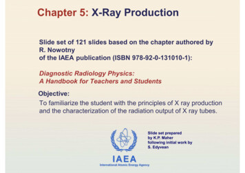
5.3 X-RAY TUBES5.3.3 AnodeThermal PropertiesThe Limiting Factor in the use of X ray tubes is given mainlyby the thermal loading capacity of the anodeMaximum PermissibleTube Load vs. time for asingle exposure, constantcurrent, 100 kV tube voltageand a 50 kW tubeThe Nominal Power isdetermined for an exposuretime of 0.1 sIAEADiagnostic Radiology Physics: a Handbook for Teachers and Students – chapter 5, 45
5.3 X-RAY TUBES5.3.3 AnodeThermal PropertiesWithin the First 100 ms the maximum load is determined bymechanical stress in the anode material developing fromtemperature gradients near the surface of the focal spot (A)As a consequence cracks can develop leading to an increasein anode surface roughnessThis effect can be reduced by:use of a more ductile alloy as the focal track (e.g.Tungsten/Rhenium alloys) oran increase in the size of the focal spot or therotational speed of the anodeIAEADiagnostic Radiology Physics: a Handbook for Teachers and Students – chapter 5, 46
5.3 X-RAY TUBES5.3.3 AnodeThermal PropertiesThe energy released in the focal spot Raises the temperatureto a max permissible level (2757 C for tungsten) for exposuresup to a few seconds thus limiting the maximum load (B)In CT and fluoroscopic procedures Longer exposure times areneeded (10 s to 200 s)Here the dissipation of heat across the Entire anodedisk becomes importantThe important physical properties are then the HeatConduction and Heat Capacity of the anode disk (C)IAEADiagnostic Radiology Physics: a Handbook for Teachers and Students – chapter 5, 47
5.3 X-RAY TUBES5.3.3 AnodeThermal PropertiesThe Heat Capacity is the energy stored in the anode disk withthe anode at its maximum permissible temperatureIt depends on the Specific Heat and Mass of the anodematerialsMolybdenum is superior to Tungsten in this respectIncreasing the mass of the anode (diameter, thickness) has itslimitations as Balancing the rotating anode becomes difficultfor the wide range of temperatures occurringIAEADiagnostic Radiology Physics: a Handbook for Teachers and Students – chapter 5, 48
5.3 X-RAY TUBES5.3.3 AnodeThermal PropertiesSince Graphite has a higher specific heat at highertemperatures than molybdenum or tungsten the heat capacitycan be increased by attaching graphite heat sinks to the backof the anode diskGraphite enhances the dissipation ofheat by Black-Body Thermal RadiationThe Maximum Permissible Load for long or continuousexposures is determined by the effectiveness of heat removalfrom the anode (D)IAEADiagnostic Radiology Physics: a Handbook for Teachers and Students – chapter 5, 49
5.3 X-RAY TUBES5.3.3 AnodeThermal PropertiesMost of the heat is removed by Thermal Radiation andabsorbed in the tube envelope and the surrounding insulatingoilThe maximum permissible temperature and the heat capacityof the Tube Housing is then the limiting factor of applicablepowerIAEADiagnostic Radiology Physics: a Handbook for Teachers and Students – chapter 5, 50
5.3 X-RAY TUBES5.3.3 AnodeThermal PropertiesHeat Conduction in traditional tubes from anode disk viastem, spindle, bearings and bearing support is not veryefficientIn some tube designs the ball bearings have been replaced byspecial bush bearings (spiral grooves bearings) with a LiquidGallium Alloy for lubricationThe Thermal Resistance of such bearings is muchlower compared to ball bearings which enhancesthe heat flow and increases the continuouspower rating of the tubeIAEADiagnostic Radiology Physics: a Handbook for Teachers and Students – chapter 5, 51
5.3 X-RAY TUBES5.3.3 AnodeThermal PropertiesIn the latest generation of X ray tubes (Rotational EnvelopeTube) the removal of heat from the anode is increasedconsiderably by directly exposing the back of the anode disk tothe cooling oilEnabling Long exposures with High anode currents asrequired in CT scansIAEADiagnostic Radiology Physics: a Handbook for Teachers and Students – chapter 5, 52
5.3 X-RAY TUBES5.3.3 AnodeTube EnvelopeThe tube envelope maintains the required Vacuum in the XRTA Failing vacuum due to leakage or degassing of the materialscauses increased ionization of the gas molecules which slowsdown the electronsFurther, a current of Positive Ions flowing back could impair ordestroy the cathode filamentThe envelope is commonly made of glass but highperformance tubes increasingly have Glass/Metal orCeramic/Metal envelopesIAEADiagnostic Radiology Physics: a Handbook for Teachers and Students – chapter 5, 53
5.3 X-RAY TUBES5.3.3 AnodeTube EnvelopeThe X ray beam exits the tube through a Window in theenvelopeTo reduce absorption the Thickness of the glass isreduced in this areaIf low-energy X rays are used as in mammography the exitport is a Beryllium window which has less absorption thanglass due to its low atomic numberIAEADiagnostic Radiology Physics: a Handbook for Teachers and Students – chapter 5, 54
5.3 X-RAY TUBES5.3.3 AnodeTube EnvelopeThe XRT (often referred to as the Insert) is installed in aHousing providing the structural support requiredTypical housingassembly for ageneral purposeXRTIAEADiagnostic Radiology Physics: a Handbook for Teachers and Students – chapter 5, 55
5.3 X-RAY TUBES5.3.3 AnodeTube EnvelopeThe space between housing and envelope is filled withTransformer Oil serving as electrical insulation and for heatremoval from the envelope surface which is heated by theinfrared radiation from the anodeThe change of the oil volume with varying temperature istaken care of by the Expansion BellowsThe oil carries the heat away to the housing byconvection sometimes enhanced by Forced Coolingwith a ventilator or heat exchangersIAEADiagnostic Radiology Physics: a Handbook for Teachers and Students – chapter 5, 56
5.3 X-RAY TUBES5.3.3 AnodeTube EnvelopeThe housing also provides Radiation Shielding to prevent anyradiation except the primary beam from leaving the housingThe inside of the housing is lined with Lead Sheets tominimize leakage radiationThe maximum acceptable exposure due to LeakageRadiation is limited by regulationTube housings also provide Mechanical Protection againstthe impact of envelope failureIAEADiagnostic Radiology Physics: a Handbook for Teachers and Students – chapter 5, 57
5.4 ENERGIZING & CONTROLLING THE XRTThe X Ray GeneratorProvides all electrical power sources and signalsrequired for the operation of the X ray tubeControls the operational conditions of X ray productionControls the operating sequence of exposure during anexamIAEADiagnostic Radiology Physics: a Handbook for Teachers and Students – chapter 5, 58
5.4 ENERGIZING & CONTROLLING THE XRTThe essential components are:a Filament Heating circuit to determine anode currenta High Voltage supplya Motor Drive circuit for the stator windings required fora rotating anode tubean Exposure Control providing the image receptor doserequiredan Operational ControlIAEADiagnostic Radiology Physics: a Handbook for Teachers and Students – chapter 5, 59
5.4 ENERGIZING & CONTROLLING THE XRTSchematic diagram of a basic X ray generatorIAEADiagnostic Radiology Physics: a Handbook for Teachers and Students – chapter 5, 60
5.4 ENERGIZING & CONTROLLING THE XRTThe Operational Control is often accomplished by amicroprocessor system but electromechanical devices are stillin useModern generators provide control of the Anode TemperaturebyMonitoring the power applied to the tube andCalculating the cooling times required according to thetube rating chartsIAEADiagnostic Radiology Physics: a Handbook for Teachers and Students – chapter 5, 61
5.4 ENERGIZING & CONTROLLING THE XRT5.4.1 Filament CircuitAn Isolated Transformer supplies the filament heating currentThe generator is Programmed to set the heating currentaccording to the tube characteristicsHeating currents range up to 10 A with voltages of 15 VACTo minimize thermal stress and increase durability, thefilament is Permanently Preheated to a temperature for whichthermionic emission is negligibleIAEADiagnostic Radiology Physics: a Handbook for Teachers and Students – chapter 5, 62
5.4 ENERGIZING & CONTROLLING THE XRT5.4.1 Filament CircuitThe Thermal Inertia of the filament limits the speed of changein tube current (e.g. falling load)Thermal Time Constants range from 50-200 msFor a frequency of heating currents of 100 or 120 Hz sometube current Ripple is due to the temperature variationsinducedFor high frequency generators the thermal inertia of thefilament suppresses Fluctuations of thermionic emissionIAEADiagnostic Radiology Physics: a Handbook for Teachers and Students – chapter 5, 63
5.4 ENERGIZING & CONTROLLING THE XRT5.4.2 Generating the Tube VoltageIrrespective of the waveform the tube
cathode and anode controls both X ray energy and yield e.g. 40 to 150 kV for general diagnostic radiology and 25 to 40 kV in mammography Thus Twomain circuits operate within the XRT: Filament circuit Tube voltage circuit 5.3 X-RAY TUBES 5.3.1 Components of the X Ray Tube Diagnostic Ra