Transcription
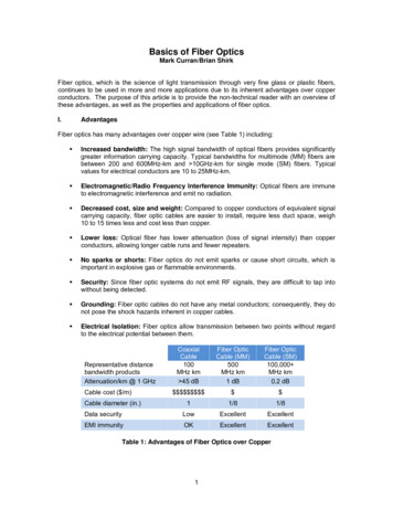
Basics of Fiber OpticsMark Curran/Brian ShirkFiber optics, which is the science of light transmission through very fine glass or plastic fibers,continues to be used in more and more applications due to its inherent advantages over copperconductors. The purpose of this article is to provide the non-technical reader with an overview ofthese advantages, as well as the properties and applications of fiber optics.I.AdvantagesFiber optics has many advantages over copper wire (see Table 1) including: Increased bandwidth: The high signal bandwidth of optical fibers provides significantlygreater information carrying capacity. Typical bandwidths for multimode (MM) fibers arebetween 200 and 600MHz-km and 10GHz-km for single mode (SM) fibers. Typicalvalues for electrical conductors are 10 to 25MHz-km. Electromagnetic/Radio Frequency Interference Immunity: Optical fibers are immuneto electromagnetic interference and emit no radiation. Decreased cost, size and weight: Compared to copper conductors of equivalent signalcarrying capacity, fiber optic cables are easier to install, require less duct space, weigh10 to 15 times less and cost less than copper. Lower loss: Optical fiber has lower attenuation (loss of signal intensity) than copperconductors, allowing longer cable runs and fewer repeaters. No sparks or shorts: Fiber optics do not emit sparks or cause short circuits, which isimportant in explosive gas or flammable environments. Security: Since fiber optic systems do not emit RF signals, they are difficult to tap intowithout being detected. Grounding: Fiber optic cables do not have any metal conductors; consequently, they donot pose the shock hazards inherent in copper cables. Electrical Isolation: Fiber optics allow transmission between two points without regardto the electrical potential between them.CoaxialCable100MHz km 45 dBFiber OpticCable (MM)500MHz km1 dBFiber OpticCable (SM)100,000 MHz km0.2 dB 11/81/8Data securityLowExcellentExcellentEMI immunityOKExcellentExcellentRepresentative distancebandwidth productsAttenuation/km @ 1 GHzCable cost ( /m)Cable diameter (in.)Table 1: Advantages of Fiber Optics over Copper1
II.Fiber Optic Link ComponentsIn order to comprehend how fiber optic applications work, it is important to understand thecomponents of a fiber optic link. Simplistically, there are four main components in a fiber optic link(Figure 1). Optical TransmitterOptical Fiber/CableConnectorsOptical ReceiverFigure 1: Simple Fiber Optic LinkII.1TransmitterThe transmitter converts the electrical signals to optical. A transmitter contains a light source suchas a Light Emitting Diode (LED) or a Laser (Light Amplification by Stimulated Emission ofRadiation) diode, or a Vertical Cavity Surface Emitting Laser (VCSEL).LED: Is used in multimode applications and has the largest spectral width that carries theleast amount of bandwidth.VCSEL: Is also used in multimode applications with a narrower spectral width that can carrymore bandwidth than the LED.LASER: Has the smallest spectral width, carries the most bandwidth, and is used insinglemode applications.These sources produce light at certain wavelengths depending upon the materials from whichthey are made. Most fiber optic sources use wavelengths in the infrared band, specifically 850nm(1nm 10-9m), 1300nm and 1550nm. For reference, visible light operates in the 400-700nm range(see Figure 2).Figure 2: Electromagnetic Spectrum2
II.2Optical Fiber/CableIn this section, we discuss the structure and properties of an optical fiber, how it guides light, andhow it is cabled for protection.An optical fiber is made of 3 concentric layers (see Figure 3): Core: This central section, made of silica or doped silica, is the light transmitting region ofthe fiber. Cladding: This is the first layer around the core. It is also made of silica, but not the samecomposition as the core. This creates an optical waveguide which confines the light in thecore by total internal reflection at the core-cladding interface. Coating: The coating is the first non-optical layer around the cladding. The coatingtypically consists of one or more layers of polymer that protect the silica structure againstphysical or environmental damage. The coating is stripped off when the fiber isconnectorized or fusion spliced.Figure 3: Optical Fiber Construction Buffer (not pictured): The buffer is an important feature of the fiber. It is 900 microns andhelps protect the fiber from breaking during installation and termination and is locatedoutside of the coating.The light is "guided" down (see Figure 4) the core of the fiber by the optical "cladding" which hasa lower refractive index (the ratio of the velocity of light in a vacuum to its velocity in a specifiedmedium) that traps light in the core through "total internal reflection."Figure 4: Diagram showing Total Internal Reflection3
In fiber optic communications, single mode and multimode fiber constructions are useddepending on the application. In multimode fiber (Figure 5), light travels through the fiberfollowing different light paths called "modes." In single mode fiber, only one mode is propagated"straight" through the fiber (Figure 6).Figure 5: Multimode Fiber Light PropagationFigure 6: Single Mode Fiber Light PropagationTypical multimode fibers have a core diameter/cladding diameter ratio of 50 microns/125 microns(10-6 meters) and 62.5/125 (although 100/140 and other sizes are sometimes used depending onthe application). Single mode fibers have a core/cladding ratio of 9/125 at wavelengths of 1300nmand 1550nm.Multimode Fiber( 62.5/125 µm )Single Mode Fiber( 9/125 µm )CoreCladdingMultimode Fiber(50/125 µm )Multimode Fiber( 100/140 µm )Figure 7: Popular Optical Fiber Core/Cladding Diameter Ratios4
Light is gradually attenuated when it travels through fiber. The attenuation value is expressed indB/km (decibel per kilometer). Attenuation is a function of the wavelength (λ) of the light. Figure 8shows the attenuation as a function of the wavelength.Figure 8: Attenuation vs. Wavelength of Optical FiberAs discussed in Section II.1, the typical operating wavelengths are 850nm (nanometers) and1300nm in multimode, and 1300nm or 1550nm in single mode. Note that there are natural "dips"in the attenuation graph at these wavelengths. For example, at an 850nm operating wavelength,there is 3dB attenuation after 1km propagation (according to the graph). 3dB of attenuationmeans that 50% of light has been lost.Bandwidth is a measure of the data-carrying capacity of an optical fiber. It is expressed as theproduct of frequency and distance. For example, a fiber with a bandwidth of 500MHz-km(Megahertz kilometer) can transmit data at a rate of 500MHz along one kilometer of fiber. Thebandwidth of single mode fibers is much higher than in multimode fibers. The main reason for thelower bandwidth in multimode fibers is modal dispersion.In multimode fibers, information (ABC) is propagated in fiber according to N modes or paths (seeFigure 9), as if it were "duplicated" N times (for example, in the diagram, the mode 3 path islonger than the mode 2 path, which are both longer than the mode 1 path). If information is tooclose, there is a risk of overlapping ("smearing") the information, and then it will not berecoverable at the end of the fiber. It is necessary to space the data sufficiently to avoid overlap,i.e., to limit the bandwidth.Figure 9: Modal Dispersion in Multimode Fibers5
Modal dispersion can be alleviated to a large extent by grading the index of refraction from themiddle of the core to the cladding (graded index fiber), thereby equalizing the paths (Figure 10).In a step index fiber, the index of refraction changes abruptly from the core to the cladding. Tohelp reduce modal dispersion, fiber manufacturers created graded-index fiber. Graded-index fiberhas an index of refraction which gradually increases as it progresses to the center of the core.Light travels slower as the index of refraction increases. Thus, a light path propagating directlydown the center of the fiber has the shortest path but will arrive at the receiver at the same timeas light that took a longer path due to the graded-index of the fiber.Figure 10: Graded Index in Multimode FibersOf course, modal dispersion is not an issue in single mode fiber because only a single mode ispropagated (Figure 11).Figure 11: Single Mode PropagationUnfortunately, the optical fiber construction shown in Figure 3 is fragile. Thus, for mostapplications, the fiber must be made into a cable. There are many ways to construct a cable (tightbuffer, loose tube, gel filled, distribution, breakout, etc). However, in our single fiber cableexample (see Figure 12), the 250 micron coating is jacketed with a 900 micron buffer and builtinto a 3.0mm outer sheath cable with aramid yarn (KevlarTM ) as a strength member. As a typicalexample, Figure 13 portrays a cable with multiple optical fibers.6
Figure 12: Construction of a Single Fiber CableFigure 13: Example of the Construction of a Multi- Fiber CableII.3ConnectivityFiber optic links require a method to connect the transmitter to the fiber optic cable and the fiberoptic cable to the receiver. In general, there are two methods to link optical fibers together.II.3.1Fusion SpliceThe first method is called a fusion splice. This operation consists of directly linking two fibers bywelding with an electric arc or a fusion splicer (see Figure 14). The advantages of this approachare that the linking method is fast and simple and there is very little insertion loss (the loss of lightgenerated by a connection is called Insertion Loss [IL]). The disadvantages are that the link isrelatively fragile, is permanent, and the initial cost (of the fusion splicer) is high.7
Figure 14: Fiber-optic Fusion SplicerII.3.2ConnectorsThe second method involves the uses of fiber optic connectors. A connector terminates theoptical fiber inside a ceramic ferrule, using epoxy to hold the fiber in place. The connectors canbe mated and unmated at any time. The advantages of this approach are that the connection isrobust, the connector can be chosen according to the application, and the connector can beconnected and disconnected hundreds or even thousands of time without damaging theconnectors. The disadvantages of this approach are that the connectorization takes longer thanfusion splicing, requires special tools, and the insertion loss can be higher when compared withfusion splicing.There are two types of fiber optic connectors: physical contact and expanded beam.II.3.2.1 Physical Contact ConnectorsPhysical contact connectors utilize fiber in a tightly toleranced ceramic ferrule. This allows easyhandling of the fiber and protects it from damage. The principle of physical contact connectorsinvolves the direct contact of polished fibers within two ceramic ferrules. The ferrules are alignedusing a ceramic alignment sleeve (see Figure 15). Insertion loss is a function of the alignmentaccuracy and the polish quality. There are springs behind the ferrule to ensure that the twoferrules are in constant contact even in high vibration and shock environments.Figure 15: Physical Contact8
Physical contact connectors are the most common type of fiber optic connection. They arerugged, repeatable, easy to clean, cost-effective, and perform well. In addition, for physicalcontact connectors, the insertion loss is generally low (approximately 0.3dB). There are manytypes of fiber optic connectors used in various applications. The most popular single fiberconnectors are (see Figure 16): FC-Ferrule Connector: Although the FC connector is being replaced in many applications(telecom and datacom) by LC and SC connectors, it is still used in measurementequipment. The connector has a screw threading and is keyed allowing the ferrule to beangle polished providing low backreflection (light is reflected back to the transmitter, mostoften at the connector interface due to an index of refraction change). LC-Lucent Connector: LC connectors are supplanting SC connectors because of theirsmaller size and excellent panel packing density and push-pull design. They are alsoused extensively on small form-factor pluggable transceivers. SC-Subscriber Connector: SC connectors also offer a push-pull design (which reducesthe possibility of end-face damage when connecting) and provide good packing density.They are still used in datacom and telecom applications. ST-Straight Tip Connector: ST connectors are engaged with a bayonet lock which isengaged by pushing and twisting the connector. The bayonet interlock maintains thespring-loaded force between the two fiber cores.Figure 16: Popular Single Fiber ConnectorsThese physical contact connectors perform well against particle contaminates (dust, mud, etc)and are usually less sensitive to liquid contaminates (water or oil). The physical contact pushesliquid out of the way and the liquid does not degrade the connection. Physical contact connectorsare cleaned by wiping the ferrule with a clean cloth or wipe, spraying with a cleaner or washingwith water.It is also common to provide multiple fibers in a single connector. An example is the MPO(Multiple Fiber Push-On/Pull-Off-see Figure 17) connector which supports 12 fibers in a singleferrule. Another example is the TFOCA-II connector which provides 4 or 12 fiber optic channelsfor harsh environment fiber-optic applications (see Figure 18).Figure 17: MPO Multi-fiber Connector9
Figure 18: AFSI TFOCA-II ConnectorII.3.2.2 Expanded Beam TechnologyThe other connector technology is expanded beam, which consists of placing a lens at the exit ofeach fiber to widen and collimate the light. In this configuration, there is an air gap between thetwo optical fibers/lens assemblies (see Figure 19).The mechanical interface between the connectors must be precise. Dust and dirt must notinterfere with the alignment of the optical elements. Expanded beam connectors are l
Basics of Fiber Optics Mark Curran/Brian Shirk Fiber optics, which is the science of light transmission through very fine glass or plastic fibers,