Transcription
Published by :http://www.ijert.orgInternational Journal of Engineering Research & Technology (IJERT)ISSN: 2278-0181Vol. 6 Issue 12, December - 2017Design and Construction of Automated StampingMachine for Small Scale IndustriesMauton Gbededo¹ ² and Olayinka Awopetu²1. Department of Mechatronics Engineering, Bells University of Technology, Ota, Ogun-State, Nigeria2. Department of Mechanical Engineering, Federal University of Technology, Akure, Ondo-State, NigeriaAbstract - Packaging is one of the end process of everymanufacturing industries as outputs are required to be stored,protected and shipped according to customers’ requirements.Most small scale industries have outsourced the end process ofmanufacturing due to high cost of using automated means ofstamping cartons, papers and nylons. Small scale industries havebeen accustomed to manual methods of stamping with lowmachine efficiency, longer delivery time, high labour costs in aquest to meet customers’ requirements. This current trend ofstamping problems has made the small scale enterprises to loselarge number of market share to the large scale manufacturingoutfits. The need to make stamping process affordable, using easyto maintain machines and also complying to rood regulatorybodies necessitated the need for this work. An AutomatedStamping Machine driven by pneumatic systems that consists ofair compressor, directional control valves, air service unit wasdesigned, fabricated, tested and operated. The FluidSim softwaremade by Festo didactic using the cascade method was adopted inthe design and stimulation of the pneumatic circuit. The selectionof materials as well as methods in relation to engineeringproperties and design parameters such safety factor, force ofrotation, stress analysis, bending moments and speed of travelswere derived during the fabrication processes. Before starting thestamping operation, the pre packed product is positioned at thebeginning of the belt travel and the belt guide prevents the packedjob from moving out of its travel due to any external constraints.The job to be imprinted was loaded in the stock hold plate on thecylinder A. The compressor and the start button of the electricmotor were switched on. The motor drives the roller over whichruns the conveyor belt that carries the job. The compressed airflows into the system from a compressor. The compressed airentered the system and passes through the Filter-Regulator –Lubricator unit. The FRL unit prepares the compressed air forutilization by the pneumatic components. Once exiting the FRLunit is started and the compressed air led into the manifold or theair distributor, immediately the manifold takes in the compressedair and splits it into the required number depending on the numberof components used and the compressed air is sent to thecomponents from the manifold. The compressed air flows to thedirection control valve that controls the cylinders. The stampingmachine utilizes two pneumatic cylinders to carry out the stampingand ejection of the prepackaged items. The two cylinders areconfigured to operate in a controlled sequential manner in orderto execute the required operations.Keywords: Small Scale Industries, Automated Stamping machine,Packaging, Pneumatic Circuit, Manufacturing industries, FilterRegulator-Lubricator unit.IJERTV6IS120029INTRODUCTIONPackaging is one of the most important productionprocesses. It is a value adding activity which the manufactureroften uses to effectively project its brands. The stampingprocess is incorporated in packaging operation to identify andconfirm to important data like product registration number,manufacturing date and expiration date that meets legal andstatutory requirements of the food industries. The importance ofpackaging can therefore cannot be over emphasized. [1]In the modern fast world of new and latest technologies,everyone goes for perfection and quickness. The presentpractice in food packaging industries is that, stamping ismanually done by operatives and may require up to sevenoperatives per line if one need to achieve a higher output. Thissingle action is time consuming, generate higher expenditureand also result to poor finishing by operatives during manualstamping process to meet production target. In order to achievehigher productivity and safe tremendous cost there is need forautomatic stamping if small scale industries are to remaincompetitive while maximizing profit.Automation has been defined as “the use of control systemssuch as pneumatics, hydraulics, electrical, electronics andcomputers to control industrial machinery and processes,reducing the use of human intervention. In small-scale andmedium scale food packaging industries there are frequent needof stamping machine to imprint images or data on their cartonsafter packaging. [2]By automating the machine, it could achieve a fullyautomated state where there is no worker interface till theinventory on the machine is exhausted hence a worker isremoved from the machine cell and employed in a cell where aworker is needed. Here the manual system would have beenreplaced by pneumatics system as it is cheaper so that theoverall cost of the automated machine is lowered and themachine is easily available for the small scale industries.The ever increasing use of cartons for product identity inthe food packaging industries cannot be over-emphasized. Thesmall scale industries cannot afford to buy and maintain animported automated stamping machines. At the same time, theycannot depend on the few industries that has stamping machinesto achieve their production targets because of hightransportation cost, cost of automation, labour cost, etc.Besides, the stamping machines in industries are operating atlow capacity because of frequent breakdown as a result of lackof spare parts for worn-out parts, which are imported. Theseproblems necessitated the need for this work with the aim ofdesigning and fabricating a low cost automated stampingmachine. By the application of pneumatics, the pneumaticswww.ijert.org(This work is licensed under a Creative Commons Attribution 4.0 International License.)19
Published by :http://www.ijert.orgInternational Journal of Engineering Research & Technology (IJERT)ISSN: 2278-0181Vol. 6 Issue 12, December - 2017cylinder with piston, which is operated by an air compressor, itis excepted that the automated stamping machine will give thesuccessive action to quickly imprint images on material withease, less bottleneck and human error.i.ii.iii.iv.v.Cascade method.Classic or intuitive method.Step counter method.Karnaugh Veitch method.Combinatorial circuit design.The main objectives of this project is:(a) to design and produce a low cost automated stampingmachine as a modification to the existing codingmachine and injet printers used in large-scale foodpackaging industries which are controlled byProgrammable Logic Control and are quite expensive,(b) to design and fabricate a machine with improvedtechnical efficiency and technology simplicity than theexisting stamping machines through the introductionof belt and rollers to increase the speed of the machineand also the incorporation of a pneumatics controlsystems to perform automatic stamping through aninserted rubber ink and;(c) to build/manufacture a product that complies with foodregulatory body in Nigeria.MATERIAL AND METHODThis section analyses the design description, designconsideration and design analysis and method used for theconstruction of an automated stamping machine.Design descriptionThe working principle and description of the prototypeautomated stamping machine for this work is as follow.Before starting the stamping operation, the pre-packedproduct is positioned at the beginning of the belt travel and thebelt guide prevents the packed job from moving out of its traveldue to any external constraints.The job to be imprinted was loaded in the stock hold plate onthe cylinder A. The compressor and the start button of theelectric motor are switched on. The motor drives the roller overwhich runs the conveyor belt that carries the job. Thecompressed air flows into the system from a compressor. Thecompressed air entered the system and passes through the FilterRegulator–Lubricator (FRL) unit . The FRL unit prepares thecompressed air for utilization by the pneumatic components.Once exiting the FRL unit is started and the compressed air ledinto the manifold or the air distributor, immediately themanifold takes in the compressed air and splits it into therequired number depending on the number of components usedand the compressed air is sent to the components from themanifold. The compressed air flows to the Direction ControlValve (DCV) that controls the cylinders. The stamping machineutilizes two pneumatic cylinders to carry out the stamping andejection of the prepackaged items. The two cylinders areconfigured to operate in a controlled sequential manner in orderto execute the required operations.MethodIn order to execute the required operations, sequential motioncircuits involving the use of more than one actuator can bedesigned using any of several available methods. These includethe following:IJERTV6IS120029The cascade method has been selected for use in the designof this stamping machine. The cascade method was designed toovercome the problem of “opposed signals”, which often occurwhen sequential control circuits are designed using the intuitiveapproach. It is the simplest and most straightforward approachfor these types of design problems. [3]The following step by step procedure need to be followedwhen using the cascade method.i. Each cylinder is represented by a letter such as A, B,C. the required movement sequence is then writtenwith ( ) representing the forward stroke of theactuators (cylinders), while (-) is used to represent thereturn stroke of the actuator.ii. The given sequence is split into a minimum number ofgroups as follows: The first group is split where the first change instroke occurs. Subsequent groups are formed such that no letteris repeated within any group. The groups are given the identity group 1, group2, group 3 etc.iii. Each group is assigned a pressure manifold such thatthe number of groups equals the number of manifolds.iv. Each pneumatic cylinder is provided with two limitswitches to detect the full forward and full retractedpositions of the actuator.v. Each pneumatic cylinder is provided with a doublepiloted 4/2 way or 5/2-way valve for movementcontrol.vi. Reversing valves, also double piloted 4/2 or 5/2 wayvalves, are provided to distribute air supply among thedifferent groups. The number of reversing valves isone less than the number of groups.The valve connections are made as follows; The output of each limit switch is connected to thepilot input corresponding to the next sequencestep. The limit switch responsible for the last step of thegiven group is connected to the pilot line of thereversing valve so as to switch supply to thesubsequent group. The manifold line is then connected to the pilotline corresponding to the first step of the nextgroup.Following the above step by step procedure, we arrive atthe following sequence of actions by the pneumatic cylinders;A , A-, B , B-. That is, we have two cylinders A and B. as thepacket comes into the stamping machine, cylinder A, whichcarries out the stamping operation, advances to make contactwith the package, thereby placing the required mark, forexample batch number, on the package. After this, it retracts.Cylinder B, which serves as an ejector then advances to pushwww.ijert.org(This work is licensed under a Creative Commons Attribution 4.0 International License.)20
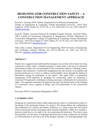
Published by :http://www.ijert.orgInternational Journal of Engineering Research & Technology (IJERT)ISSN: 2278-0181Vol. 6 Issue 12, December - 2017the package out of the stamping tunnel, before retracting tomake way for the next package to come into the tunnel. Thensequence is then ready for repetition, and continues as long asthere is supply of packages from the attached conveyor.Breaking down these sequence into groups, we have; A group 1. A-, B as group 2. B- as group 3.Thus we have three groups in total. The number ofreversing valves is then 3-1 2. The complete pneumatic circuitdiagram for this control operation is shown in figure 1. Thecircuit was simulated using the software Fluidsim version 4.2from FESTO, and it successfully exhibited all expectedbehavior. [4]iv. The specifications mostly used were those of AmericanSociety of Mechanical Engineers (ASME) code.Material SelectionComponents’ materials used in the cause of this work areselected based on the following factors:a. Properties: The materials selected must possess thenecessary properties for the proposed application. Thevarious requirements to be satisfied can be weight,surface finish, rigidity, ability to withstandenvironment attack from chemicals, service life,reliability etc. The following four types of principleproperties of materials decisively affect their selection. PhysicsMechanicalFrom manufacturing point of viewChemicalThe various physical properties concerned are meltingpoint, thermal conductivity, specific heat, efficient of thermalexpansion, specific conductivity magnetic purpose etc.The various mechanical properties concerned are strength intensile, comprehensive shear, bearing tensional and buckingload, fatigue resistance impact resistance, elastic limit, andmodulus of elasticity, harness, wear resistance and slidingproperties. [6]The various properties concerned from the manufacturingpoint of view are.Fig. 3.1: Pneumatic circuit for sequential control of the motion; A A-B B-.Design ConsiderationThe design of a machine requires the inter-relatedconsideration of a number of factors, such as material and heattreatment, strength for power and loading requirements,pressure, volume, weight and space limitations etc. With theobjectives of this project in mind, the design and fabrication ofthe machin
The stamping machine utilizes two pneumatic cylinders to carry out the stamping and ejection of the prepackaged items. The two cylinders are configured to operate in a controlled sequential manner in order to execute the required operations. Keywords: Small Cited by: 1Publish Year: 2017Author: Mauton Gbededo, Olayinka Awopetu