Transcription
The Design and Constructionof anIntelligent Power Assist Jib CraneHarry M. PearceA thesis submitted to the faculty ofNorthwestern Universityin partial fulfillment of the requirements for the degree ofMaster of ScienceinMechanical EngineeringDepartment of Mechanical EngineeringNorthwestern UniversityAugust 27th, 1999
AbstractCurrent material handling systems exhibit anisotropic behavior. That is, their two planar degrees offreedom require different amounts of force input from the operator. Movement of these devices iscorrespondingly difficult.One of the three most prevalent material handling devices, the jib crane, is selected for research intocreating isotropic motion. A platform for this research is created with two intended future directions inmind. The first direction creates isotropy by floating the boom over the load. The second directionadds a powered trolley and is capable of providing power assist to actually accelerate the load.The thesis walks the reader through the design of the platform. Selection of the jib crane is followed bythe design and selection of a servo motor and transmission capable of supporting both future directions.A cable angle sensor and ultrasonic distance sensor provide the intelligence necessary to achieveisotropy.i
Table of Contents1 Introduction . . . . . . . . . . . . . . . . . . . . . . . . . . . . . . . . . . . . . . . . . . . . . . . . . . . . . . . . . . . 12 Design Analysis . . . . . . . . . . . . . . . . . . . . . . . . . . . . . . . . . . . . . . . . . . . . . . . . . . . . . . . . . 4Jib Crane Selection . . . . . . . . . . . . . . . . . . . . . . . . . . . . . . . . . . . . . . . . . . . . . . . . . 5Acceleration and Velocity Goals . . . . . . . . . . . . . . . . . . . . . . . . . . . . . . . . . . . . . . . . 5Mass Moment of Inertia Calculations . . . . . . . . . . . . . . . . . . . . . . . . . . . . . . . . . . . . 6Mass Moment of Inertia of Upper Pivot . . . . . . . . . . . . . . . . . . . . . . . . . . . . 6Mass Moment of Inertia of Boom Mount . . . . . . . . . . . . . . . . . . . . . . . . . . . 7Mass Moment of Inertia of Boom . . . . . . . . . . . . . . . . . . . . . . . . . . . . . . . . . 8Mass Moment of Inertia of Trolley . . . . . . . . . . . . . . . . . . . . . . . . . . . . . . . . 9Mass Moment of Inertia of Load and Chain . . . . . . . . . . . . . . . . . . . . . . . . . 9Total Moment of Inertia . . . . . . . . . . . . . . . . . . . . . . . . . . . . . . . . . . . . . . . . 9Design Torque . . . . . . . . . . . . . . . . . . . . . . . . . . . . . . . . . . . . . . . . . . . . . . . . . . . . 10Design Angular Speed . . . . . . . . . . . . . . . . . . . . . . . . . . . . . . . . . . . . . . . . . . . . . . 11Transmission Type Selection . . . . . . . . . . . . . . . . . . . . . . . . . . . . . . . . . . . . . . . . . . 11Rollerchain Selection . . . . . . . . . . . . . . . . . . . . . . . . . . . . . . . . . . . . . . . . . . . . . . . 13Allowable Transmission Ratios . . . . . . . . . . . . . . . . . . . . . . . . . . . . . . . . . . . . . . . 15Motor and Gearhead Selection . . . . . . . . . . . . . . . . . . . . . . . . . . . . . . . . . . . . . . . . 15Inertia Matching . . . . . . . . . . . . . . . . . . . . . . . . . . . . . . . . . . . . . . . . . . . . . 18Regeneration . . . . . . . . . . . . . . . . . . . . . . . . . . . . . . . . . . . . . . . . . . . . . . . 19Continuation of Rollerchain Transmission Design . . . . . . . . . . . . . . . . . . . . . . . . . . . 22Rollerchain Verification . . . . . . . . . . . . . . . . . . . . . . . . . . . . . . . . . . . . . . . . 22Center Distance . . . . . . . . . . . . . . . . . . . . . . . . . . . . . . . . . . . . . . . . . . . . . 23Motor Mount . . . . . . . . . . . . . . . . . . . . . . . . . . . . . . . . . . . . . . . . . . . . . . . . . . . . . 24Electrical Enclosure . . . . . . . . . . . . . . . . . . . . . . . . . . . . . . . . . . . . . . . . . . . . . . . . 27Sensors to Add Intelligence . . . . . . . . . . . . . . . . . . . . . . . . . . . . . . . . . . . . . . . . . . 28Cable Angle Sensor . . . . . . . . . . . . . . . . . . . . . . . . . . . . . . . . . . . . . . . . . . 28Radial Position Sensor . . . . . . . . . . . . . . . . . . . . . . . . . . . . . . . . . . . . . . . . 303 Experimental Results . . . . . . . . . . . . . . . . . . . . . . . . . . . . . . . . . . . . . . . . . . . . . . . . . . . . 354 Conclusion . . . . . . . . . . . . . . . . . . . . . . . . . . . . . . . . . . . . . . . . . . . . . . . . . . . . . . . . . . . 39Future Work . . . . . . . . . . . . . . . . . . . . . . . . . . . . . . . . . . . . . . . . . . . . . . . . . . . . . 39Appendix A–Drawings . . . . . . . . . . . . . . . . . . . . . . . . . . . . . . . . . . . . . . . . . . . . . . . . . . . . 42Appendix B–Component Information . . . . . . . . . . . . . . . . . . . . . . . . . . . . . . . . . . . . . . . . . 59Appendix C–Conversion Factors . . . . . . . . . . . . . . . . . . . . . . . . . . . . . . . . . . . . . . . . . . . . 60ii
List of FiguresFigure 1.1 Jib Crane Anatomy . . . . . . . . . . . . . . . . . . . . . . . . . . . . . . . . . . . . . . . . . . . . . . . . . . . . 1Figure 1.2 Articulating Arm Jib Crane . . . . . . . . . . . . . . . . . . . . . . . . . . . . . . . . . . . . . . . . . . . . . . 2Figure 1.3 Gantry Crane . . . . . . . . . . . . . . . . . . . . . . . . . . . . . . . . . . . . . . . . . . . . . . . . . . . . . . . . . 2Figure 1.4 Bridge Crane . . . . . . . . . . . . . . . . . . . . . . . . . . . . . . . . . . . . . . . . . . . . . . . . . . . . . . . . . 2Figure 2.1 Coordinate System . . . . . . . . . . . . . . . . . . . . . . . . . . . . . . . . . . . . . . . . . . . . . . . . . . . . . 4Figure 2.2a Bushing Joint . . . . . . . . . . . . . . . . . . . . . . . . . . . . . . . . . . . . . . . . . . . . . . . . . . . . . . . . 5Figure 2.2b Hinge Joint . . . . . . . . . . . . . . . . . . . . . . . . . . . . . . . . . . . . . . . . . . . . . . . . . . . . . . . . . . 5Figure 2.3 Velocity and Acceleration Experimental Platform . . . . . . . . . . . . . . . . . . . . . . . . . . . . 5Figure 2.4 Components of the Jib Crane which Add to the Rotational Moment of Inertia . . . . . . 6Figure 2.5 Cross Section for Error Analysis . . . . . . . . . . . . . . . . . . . . . . . . . . . . . . . . . . . . . . . . . . 8Figure 2.6 Torque Necessary to Achieve Acceleration Goal as a Function of Trolley RadialPosition and Load Weight . . . . . . . . . . . . . . . . . . . . . . . . . . . . . . . . . . . . . . . . . . . . . . 10Figure 2.7 Desired Angular Speed as a Function of the Trolley’s Radial Position . . . . . . . . . . . . 11Figure 2.8 Location of Transmission . . . . . . . . . . . . . . . . . . . . . . . . . . . . . . . . . . . . . . . . . . . . . . 12Figure 2.9 Cable Transmission . . . . . . . . . . . . . . . . . . . . . . . . . . . . . . . . . . . . . . . . . . . . . . . . . . . 12Figure 2.10 Chordal Action Schematic . . . . . . . . . . . . . . . . . . . . . . . . . . . . . . . . . . . . . . . . . . . . . 13Figure 2.11 Rollerchain Power Rating Table . . . . . . . . . . . . . . . . . . . . . . . . . . . . . . . . . . . . . . . . 14Figure 2.12 Torque Curve for Selected Motor . . . . . . . . . . . . . . . . . . . . . . . . . . . . . . . . . . . . . . . 17Figure 2.13 Motor Mount . . . . . . . . . . . . . . . . . . . . . . . . . . . . . . . . . . . . . . . . . . . . . . . . . . . . . . . 25Figure 2.14 Forces on Small Sprocket from Chain . . . . . . . . . . . . . . . . . . . . . . . . . . . . . . . . . . . 25Figure 2.15 Collage of Pictures taken during Motor Mount Machining . . . . . . . . . . . . . . . . . . . 26Figure 2.16 Motor Mount, Servo Motor, and Rollerchain Transmission . . . . . . . . . . . . . . . . . . . 26Figure 2.17 Dead Man Switch . . . . . . . . . . . . . . . . . . . . . . . . . . . . . . . . . . . . . . . . . . . . . . . . . . . . 27Figure 2.18 Electrical Enclosure Housing Drive and Regeneration Resistor . . . . . . . . . . . . . . . . 27Figure 2.19 Cable Angle Sensor and Enclosure . . . . . . . . . . . . . . . . . . . . . . . . . . . . . . . . . . . . . . 28Figure 2.20 Cable Angle Sensor and Fabricated Enclosure . . . . . . . . . . . . . . . . . . . . . . . . . . . . . 29Figure 2.21 Cable Angle Calculation . . . . . . . . . . . . . . . . . . . . . . . . . . . . . . . . . . . . . . . . . . . . . . 30Figure 2.22 Conical Beam Pattern of Emitted Sound Wave . . . . . . . . . . . . . . . . . . . . . . . . . . . . 31Figure 2.23 Ultrasonic Sensor Attached to Boom . . . . . . . . . . . . . . . . . . . . . . . . . . . . . . . . . . . . 32Figure 2.24 Ultrasonic Sensor Mount . . . . . . . . . . . . . . . . . . . . . . . . . . . . . . . . . . . . . . . . . . . . . . 32Figure 2.25 CW and CCW Limit Switches . . . . . . . . . . . . . . . . . . . . . . . . . . . . . . . . . . . . . . . . . . 33Figure 2.26 Completed Platform for an Intelligent Power Assist Jib Crane . . . . . . . . . . . . . . . . 34Figure 2.27 Motor Current and Motor Angular Speed in Response to a Velocity Step Inputof 100 RPM . . . . . . . . . . . . . . . . . . . . . . . . . . . . . . . . . . . . . . . . . . . . . . . . . . . . . . . . 35Figure 2.28 Velocity Response to a Constant Torque (Current) Command . . . . . . . . . . . . . . . . . 36Figure 2.29 Cable Angle Sensor Response to Jib Crane Motion . . . . . . . . . . . . . . . . . . . . . . . . . 37Figure 2.30 Voltage Output from Ultrasonic Sensor . . . . . . . . . . . . . . . . . . . . . . . . . . . . . . . . . . 38Figure 2.31 Diagram Showing Inability of Cable Angle Sensor to Measure Intent when Loadmust be Accelerated . . . . . . . . . . . . . . . . . . . . . . . . . . . . . . . . . . . . . . . . . . . . . . . . . 39iii
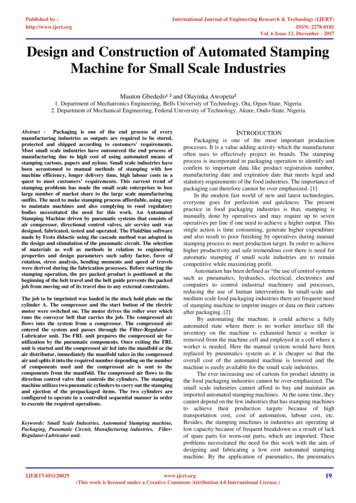
1IntroductionEntrance into the durable goods manufacturing plant of today is marked by the dominance of overheadmaterial handling systems. The purpose of these devices is simply to help workers move objects,weighing from 30 pounds to 100 tons, from one point to another. The overhead material handlingsystems discussed here have three degrees of freedom (DOF). The two degrees of freedom in thehorizontal plane are provided by motion of beams and trolleys, while the third, vertical degree offreedom is provided by a hoist. There exist three such types of systems.The first 3-DOF material handling device and the one which is the subject of this thesis, is the jib crane,depicted in Figure 1.1. An anatomical description begins with the mast. Figure 1.1 shows a mastwhich is secured to the floor, but other types of masts can be mounted to a wall or ceiling. A rotationaljoint permits the boom (translucent in the figure) to rotate about the mast. While Figure 1.1 shows anaxle and bushing type joint, joints with two or more hinges (like on a door) are common. There aretwo types of booms: enclosed track booms (shown in the figure) have a channel in which a trolley rides.This design keeps the rolling surface clean, significantly reducing rolling friction. The greater stiffnessper unit mass of the I-beam boom provides increased capacity, greater span, and slightly lower inertia.A hybrid boom combines the stiffness of the I-beam with the low friction of the enclosed track bystacking two such beams on top of one another. To finish up the description, a trolley translates alongthis boom. A cable or chain, often in conjunction with a hoist, suspends a load from the trolley.Figure 1.1 Jib Crane Anatomy This figure depicts the parts of a typicaljib crane. The boom is shown translucent for clarity.1
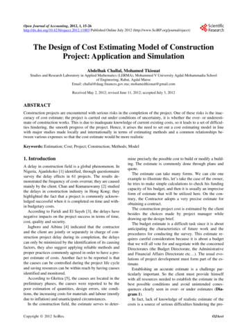
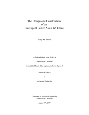
A variant of the standard jib crane is the articulating arm jib crane, shown in Figure 1.2. It has notrolley and thus no boom. Instead, it has two arms joined by apivot joint, which allows up to 360 degrees of rotation of thesecond arm relative to the first. There is an attachment point atthe end of the second arm for a chain, cable, or hoist. Theadvantage of the articulating arm over the standard jib is asfollows: the moment of inertia of the two arms is generally less Figure 1.2 Articulating Arm Jibthan that of a comparable boom. This means motionsCraneperpendicular to the boom’s length on a standard jib cranerequire more force. Forces along the boom on a standard jib crane, however, often require less forcedue to the even lower inertia of the trolley.The two other types of overhead material handling machines are the gantry crane (Figure 1.3) andbridge crane (Figure 1.4). Both types have a rail (identical to a boom) and trolley similar to those onthe jib crane. On the gantry crane, though, the rail is rigidly attached to two supports which roll alongthe ground, often in tracks. On the bridge crane, one or two rails form a bridge across two fixed rails.In Figure 1.4, the one rail which forms the bridge is shown in yellow. This bridge then has two or fourtrolleys at each end to allow movement along the fixed rails.The three material handling machines exhibit a tradeoff between high load capacity and low spaceinfringement. The cantilevered mount of the jib crane gives it a lower capacity than similarly sizedgantry and bridge cranes, where the boom is supported at both ends. This same characteristic,however, allows the jib crane to take up significantly less floor space. The bridge crane necessitates theconstruction of a large frame around the perimeter and/or over the top of its rectangular work space.The gantry crane usually necessitates the mounting of track (for safety reasons) and the existence of thetwo mobile supporting columns along its rectangular workspace. In contrast, a jib crane merelyrequires the mounting of a slender mast at the center of a circular workspace or the attachment to a wallalong a semicircular workspace. The large rolling mass of the gantry crane creates a safety problemand often necessitates powered motion; thus it is generally restricted to outdoor applications where theuse of tracks allow for longFigure 1.3 Gantry CraneFigure 1.4 Bridge Crane2
distance movements. For this rea
Figure 1.1 Jib Crane Anatomy This figure depicts the parts of a typical jib crane. The boom is shown translucent for clarity. 1 Introduction Entrance into the durable goods manufacturing plant of today is marked by the dominance of overhead material handling systems. The purpose of these devices is simply to help workers move objects, weighing from 30 pounds to 100 tons, from one point to .