Transcription
Guidance Notes on Structural Analysis of Self-Elevating UnitsGUIDANCE NOTES ONSTRUCTURAL ANALYSIS OF SELF-ELEVATING UNITSAPRIL 2016American Bureau of ShippingIncorporated by Act of Legislature ofthe State of New York 1862Copyright 2016American Bureau of ShippingABS Plaza16855 Northchase DriveHouston, TX 77060 USA
ForewordForewordThe guidance contained herein should be used in conjunction with the ABS Rules for Building andClassing Mobile Offshore Drilling Units for the purpose of ABS Classification of a Self-Elevating Unit.The guidance indicates acceptable practice in a typical case for types of designs that have been usedsuccessfully over many years of service. The guidance may need to be modified to meet the needs of aparticular case, especially when a novel design or application is being assessed. The guidance should notbe considered mandatory, and in no case is this guidance to be considered a substitute for the professionaljudgment of the designer or analyst. In case of any doubt about the application of this guidance ABSshould be consulted.A self-elevating unit is referred to herein as an “SEU”, and the ABS Rules for Building and ClassingMobile Offshore Drilling Units, are referred to as the “MODU Rules”.These Guidance Notes become effective on the first day of the month of publication.Users are advised to check periodically on the ABS website www.eagle.org to verify that this version ofthese Guidance Notes is the most current.We welcome your feedback. Comments or suggestions can be sent electronically by email to rsd@eagle.org.0HTerms of UseThe information presented herein is intended solely to assist the reader in the methodologies and/or techniquesdiscussed. These Guidance Notes do not and cannot replace the analysis and/or advice of a qualifiedprofessional. It is the responsibility of the reader to perform their own assessment and obtain professionaladvice. Information contained herein is considered to be pertinent at the time of publication, but may beinvalidated as a result of subsequent legislations, regulations, standards, methods, and/or more updatedinformation and the reader assumes full responsibility for compliance. This publication may not be copiedor redistributed in part or in whole without prior written consent from ABS.iiABS GUIDANCE NOTES ON STRUCTURAL ANALYSIS OF SELF-ELEVATING UNITS . 2016
Table of ContentsGUIDANCE NOTES ONSTRUCTURAL ANALYSIS OF SELF-ELEVATING UNITSCONTENTSSECTION 1Introduction . 11Overview . 13General Requirements of Strength Analysis. 15Information Required for Strength Analysis . 17SECTION 25.1Unit’s Data . 15.3Gravity and Functional Load. 25.5Environmental Data . 2Methods of Analysis . 87.1Static Response . 87.3Dynamic Response . 8TABLE 1Wind Pressure Height Coefficients . 3FIGURE 1Plot of Wind Force Height Coefficient vs. Height aboveDesign Water Surface . 4FIGURE 2Current Velocity Profile . 7FIGURE 3Water Depth . 7Loads. 91Overview . 93Gravity and Functional Loads . 95Wind Load . 1075.1Wind Load on Open Truss. 105.3Wind Load on Leg . 115.5Dynamic Effects and Vortex Induced Vibration . 11Wave and Current Loads . 117.1Validity and Application of the Morison’s Equation . 117.3Hydrodynamic Coefficients . 127.5Wave Theories . 197.7Asymmetry . 207.9Stretching . 207.11Shielding. 217.13Wave Approach Angle . 217.15Breaking Wave and Slamming . 217.17Stepping Wave through Structures . 22ABS GUIDANCE NOTES ON STRUCTURAL ANALYSIS OF SELF-ELEVATING UNITS . 2016iii
91113Large Displacement Load (P- Effect) .229.1Large Displacement Method . 229.3Geometric Stiffness Method . 22Dynamic Load (Inertial Effect).2411.1Magnitude of Inertial Load . 2411.3Distribution of Inertial Load . 24Leg Inclination .24TABLE 1SECTION 3SECTION 4ivP- Effect Approaches .23FIGURE 1Non-cylindrical Chords .13FIGURE 2ADrag Coefficient of Tubular Chord with Rack: DeterministicAnalysis .14FIGURE 2BDrag Coefficient of Triangular Chords: DeterministicAnalysis .14FIGURE 3One Bay of Lattice Leg .17FIGURE 4Split-Tube Chord Section .17FIGURE 5Triangular Chord Section .18FIGURE 6Wave Theories Applicability Regions (After API RP2A) .19FIGURE 7Wheeler Stretching of Wave .21Structural Analysis Models . 251Overview .253Structural Model .253.1Hierarchy of Models . 253.3Hull Model . 273.5Leg Model . 283.7Leg-to-Hull Connection Model . 303.9Foundation Modeling . 36TABLE 1Applicability of Leg Models .25TABLE 2Applicability of Hull Models .25TABLE 3Applicability of Connection Models .26TABLE 4Comparisons of Global Models .26FIGURE 1Simplified Guide Modeling .33FIGURE 2Linearization of Guides .35FIGURE 3Eccentricity of Spudcan .37Structural Analyses . 381Overview .381.1Two-Step Procedure Analysis . 381.3Step 1 – Dynamic Analysis and Inertial Load Set . 381.5Step 2 – Quasi-static Analysis . 391.7Critical Storm Load Directions . 401.9Exception . 40ABS GUIDANCE NOTES ON STRUCTURAL ANALYSIS OF SELF-ELEVATING UNITS . 2016
3579SECTION 5Specification of Wave Parameters and Spudcan-Soil Stiffness . 413.1Introduction. 413.3Spectral Characterization of Wave Data for Dynamic Analysis . 423.5Spudcan-Soil Rotational Stiffness (SC-S RS) . 42Dynamic Analysis Modeling . 435.1Introduction. 435.3Stiffness Modeling . 435.5Modeling the Mass . 455.7Hydrodynamic Loading . 455.9Damping . 45Dynamic Response Analysis Methods . 467.1General. 467.3Random Wave Dynamic Analysis in Time Domain . 467.5Other Dynamic Analysis Methods . 53Dynamic Amplification Factor and Inertial Load Set . 559.1Introduction. 559.3Inertial Load Set based on Random Wave Dynamic Analysis . 559.5Inertial Load Set based on SDOF Approach . 569.7Inertial Load Set Applications . 56FIGURE 1Flowchart of Two-step Procedure . 41FIGURE 2The Drag-Inertia Method Including DAF Scaling Factor . 50FIGURE 3Graphical Representation of DAF Scaling Factor, FDAF,Applied in the Drag-Inertia Method . 51Commentary on Acceptance Criteria . 571Introduction . 573Categories of Criteria . 575Wave Crest Clearance and Air Gap . 577Overturning Stability. 579Structural Strength . 589.1Yield Criteria . 589.3Buckling Criteria . 599.5Hybrid Members . 599.7Punching Shear . 609.9P- Effect on Member Checking . 6011Fatigue of Structural Details. 6013Strength of the Elevating Machinery . 6015Spudcan Check. 611715.1Preload Condition . 6115.3Normal Operating and Severe Storm Conditions . 61Other Checks . 61FIGURE 1Chords Section Stress Points . 60ABS GUIDANCE NOTES ON STRUCTURAL ANALYSIS OF SELF-ELEVATING UNITS . 2016v
APPENDIX 1 Equivalent Section Stiffness Properties of a Lattice Leg . 621Introduction .623Formula Approach .623.1Equivalent Shear Area of 2D Lattice Structures . 623.3Equivalent Section Stiffness Properties of 3D Lattice Legs . 63TABLE 1Equivalent Shear Area of 2D Lattice Structures .64TABLE 2Equivalent Moment of Inertia Properties of 3D LatticeLegs .65FIGURE 1Shear Force System for X Bracing and its EquivalentBeam .62APPENDIX 2 Equivalent Leg-to-Hull Connection Stiffness Properties . 661Introduction .663Empirical Formula Approach.6653.1Horizontal Stiffness . 663.3Vertical Stiffness . 663.5Rotational Stiffness . 66Unit Load Approach .675.1Unit Axial Load Case . 675.3Unit Moment Case . 675.5Unit Shear Load Case . 67APPENDIX 3 References . 68viABS GUIDANCE NOTES ON STRUCTURAL ANALYSIS OF SELF-ELEVATING UNITS . 2016
Section 1: Introduction1SECTION1IntroductionOverviewThese Guidance Notes provide suggested practices that can be used in the structural analysis of a selfelevating unit (also referred to herein as an ‘SEU’ or a ‘unit’) in the elevated condition. The emphasis is onanalyses that are used to assess the structural strength of the unit to resist yielding and buckling failuremodes considering the static, and as needed the dynamic, responses of the unit in accordance with the ABSRules for Building and Classing Mobile Offshore Drilling Units (MODU Rules). As an aid to users of theRules, these Guidance Notes also provide explanations on the intent and background for some of therelated criteria contained in the Rules.3General Requirements of Strength AnalysisA unit’s modes of operation in an elevated condition should be investigated using anticipated loads,including gravity, functional and environmental loads. The Owner is to specify the environmentalconditions for which the plans for the unit are to be approved. Owners or designers are to thoroughlyinvestigate the environmental and loading conditions for each water depth considered in the Classification.It is the Owner’s responsibility to ensure that the unit is not exposed to conditions more severe than thosefor which it has been approved.A unit with an ‘Unrestricted Classification’ is designed considering a minimum wind speed of 100 knots inthe elevated severe storm condition, and 70 knots in the elevated normal drilling condition. The wave andother conditions that accompany these winds are to be as specified by the Owner. These other conditions,especially those related to waves and currents may not be the maximum values that are expected during theoperational life of the unit. Accordingly other sets of environmental and other design parameters aretypically specified by the Owner and are included in the scope of the unit’s Classification.5Information Required for Strength AnalysisSufficient information needs to be obtained to adequately perform the structural analysis on the unit.5.1Unit’s DataBasic information about the unit’s configuration is required for the analysis. These data are summarizedbelow.5.1.1Structural InformationMost of the structural information is obtained from relevant drawings and reports. These data canbe categorized as: The primary sizes, scantlings and locations of structural members The detailed sections, connections and localized designs of structural members The material properties of structural members The characteristics of some machinery equipment that affect structural responseABS GUIDANCE NOTES ON STRUCTURAL ANALYSIS OF SELF-ELEVATING UNITS . 20161
Section1IntroductionIn particular, the properties of leg-to-hull connections are of great importance and need specialattention:5.1.25.3 The basic configuration and arrangement of connections, which include pinions, chocks (ifany), upper/lower guides, jacking case, shock pads (if any), etc. The stiffness and capacity of pinions and chocks (if any) The gap between leg chords and upper/lower guides The detailed structural configuration of jacking case The detailed structural configuration of upper/lower guidesOther InformationOther data that are required for the SEU strength analysis include: Wind projected areas of the hull, deckhouses, derrick, drilling floor and leg in each direction The capacity and moving range of the cantilever The capacity of jacking systemGravity and Functional LoadThe gravity loads include: steel weights, equipment and outfitting weights, the weights of liquid and solidvariable quantities; and live loads. The gravity loads should be taken into account for the structural designand stability. The load effects due to operations such as drilling, work over and well servicing (rotary/hookloads and tensioner loads) should also be taken into account as functional loads.For all modes of operation, the combinations of gravity and functional loads are specified by the Owner forthe operations considered in the design. However, maximums (or minimums) of the combinations thatproduce the most unfavorable load effects on the unit’s strength or stability should be used in the design.Total elevated load defined in 3-1-1/16 of the MODU Rules consists of the lightship weight excluding legsand spudcans, all shipboard and drilling equipment and associated piping, the liquid and solid variablesand combined drilling (functional) load. The total elevated load is normally used to identify the capacity ofan SEU in the elevated mode.The following information needs to be collected:5.52 The magnitude and distribution of the lightship weight The magnitude and distribution of variable loads The magnitude and location of functional loads The magnitude and distribution of the total elevated load Extreme limits of center of gravity for the whole hull and the corresponding load magnitude Weight, center of gravity and buoyancy of the legs including non-structural parts.Environmental DataEnvironmental loads contribute most of the horizontal forces acting on a unit, which are usually thecontrolling factors to determine the capacity of the unit. Below, the environmental data requirements as per3-1-3 of MODU Rules are discussed. Each of the following environmental parameters that affect the loadsacting on a jack-up unit is discussed: Wind Wave Current Water depthABS GUIDANCE NOTES ON STRUCTURAL ANALYSIS OF SELF-ELEVATING UNITS . 2016
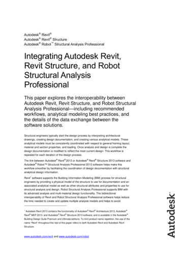
Section1Introduction Airgap and wave clearance Geotechnical data5.5.1WindThe MODU Rules specify that for unrestricted offshore service, a unit should be designed for anoperating wind velocity of at least 36 m/s (70 knots) and at least 51.5 m/s (100 knots) for a severestorm condition.5.5.1(a) Wind Profile. The wind velocity increases with height above the still water level. TheMODU Rules specify a profile as given in Section 1, Table 1 to be applied when calculating thewind pressure. This is not a complete listing of the table as given in the Rules, but may besufficient for most elevated SEU analyses. (A complete listing is given in 3-1-3/Table 2 of theMODU Rules.) It is important to note that this is NOT a wind velocity profile. Velocity profilefactors are squared during the calculation of wind force. In order to compare the wind pressurecoefficients with a wind velocity profile, it is necessary to either square the velocity profileordinates, or take the square root of the Rules’ pressure coefficients.TABLE 1Wind Pressure Height CoefficientsHeight (m)Height 91.5250-3001.4391.5-106.5300-3501.48Section 1, Figure 1 gives a plot of the MODU Rules specified height coefficient, Ch in conjunctionwith various others. The “API 1 min Force Profile” is the wind force profiles as suggested in APIRP 2A, but modified from a velocity profile, to a force profile. The basic form of these profiles is: Vh Vref h href 1 n whereVh wind velocity at elevation h above the mean sea levelVref wind velocity at the reference heighthref reference height 10 meters (33 feet)1/n exponent of the velocity profile. Note that if the exponent of the velocityprofile is 1/n the exponent of the force profile will be 2/nIn older versions of API RP 2A it was suggested that the exponent should range between 1/13 forgusts, and 1/8 for sustained winds, but there was no definition of “gusts” or “sustained” winds.The twentieth edition modifies the format and gives an exponent of 1/8 for a one hour wind, butthen gives a more complex conversion to a height profile for the one minute mean wind. It is thismodified one minute mean wind speed profile that has been plotted in Section 1, Figure 1.ABS GUIDANCE NOTES ON STRUCTURAL ANALYSIS OF SELF-ELEVATING UNITS . 20163
Section1IntroductionOne of the major causes of difference between different profiles in Section 1, Figure 1 is due tochanges in the reference height. The ABS profile is for a wind measured at a reference height of50 feet, whereas the API profiles are for a wind measured at a reference height of 33 feet. Thiscan be a major cause of the differences between different sets of height coefficients. If the APIRP-2A one-minute wind profile were plotted with respect to the same reference height as the ABSCh profile, the results would be very similar.FIGURE 1Plot of Wind Force Height Coefficient vs. Height above Design Water Surface60.0Force Profilefor 1/12Velocity Profile50.0API 1 minForceProfileForceProfile for1/8 VelocityProfile40.0ABS Ch30.020.010.01/8 and 1/12 Profiles of form:Vz V1.0m(Z/1.0m)1/n011.21.41.61.822.2Wind Force Height Coef5.5.2WaveThe Owner may specify wave criteria as either irregular sea states or deterministic regular waveshaving shape, size, and period appropriate to the water depth in which the unit is to operate.In the deterministic design procedure, the design wave is defined as a regular wave described bythe maximum wave height (Hmax) and its associated wave period (Tass) for each water depth inwhich the unit is to operate.In the stochastic design procedure, a short-term irregular sea state is defined in terms of a waveenergy spectrum characterized by a significant wave height (Hsrp) and a zero-crossing wave period(Tz). The spectrum should reflect the shape and width of typical spectra appropriate to the depthof water in which the unit is to operate. For a fully developed sea, the Pierson-Moskowitz (P-M)spectrum may be applied. For long swells or locations with a limited “fetch”, a narrower spectrum(e.g., JONSWAP spectrum) should be used. See also 4/3.3 regarding wave parameters. Long-termwave statistics can be described by a family of irregular sea states in a wave scatter diagram.4ABS GUIDANCE NOTES ON STRUCTURAL ANALYSIS OF SELF-ELEVATING UNITS . 2016
Section1Introduction5.5.2(a) Design Wave Selection. The selected design wave should induce the most unfavorableresponse of the structure under consideration. Most SEU analyses for Classification are based on adeterministic wave approach, even when dynamics are being included, although appropriatespectral data can be used.The wave (and current) conditions, which are to be combined with the Rule required minimumwind speeds, are those specified by the Owner. For other wave conditions specified by the Ownerfor inclusion in the scope of classification, they should be the maximum wave heights appropriateto the depths of water in which the unit is expected to operate.Where dynamic effects are insignificant, the wave forces on an SEU are not too sensitive to thechoice of wave period, except in unusual cases (e.g., where wave force cancellation occurs). It istherefore normally acceptable to use the maximum wave height with a single “Associated WavePeriod”, as described below. Where dynamic effects are considered potentially significant, thechoice of period can be critical, thus a range of wave periods associated with a range of waveheights are to be investigated.At a certain wave period, the wave forces acting on an SEU will be significantly reduced due toforce cancellation. The selected design wave should not be a wave that causes wave forcecancellation. This occurs when there is a wave crest at one leg (or a set of legs) and a trough atanother. For example, a unit with a leg spacing of 60 meters (200 feet) will experiencecancellation in regular waves of approximately 8.8-second period. The length of an 8.8-secondwave is 120 meters (400 feet) which is twice the leg spacing. The effect is more severe for fourlegged units than for three legged units. In the extreme case, the wave force on a four legged unitwill be reduced to zero with perfect cancellation, whereas a three legged unit will effectivelyalways have a different number of legs at the crest then at the trough. It is also possible to havewave force reinforcement at shorter wave periods, with wave crests at both sets of legs. Bothreinforcement and cancellation can also occur at shorter periods due to harmonic effects. Undercertain circumstances, the response to the component of the sea state close to resonance may besignificantly reduced if the periods of resonance and cancellation happen to coincide.5.5.2(b) Variations in Defining Wave Periodsi)Peak Period (Tp). Also known as the “Modal Period”, it is the wave period associatedwith the “peak” of the wave energy spectrum. It is normally longer than the periodassociated with the maximum wave.ii)Mean Period (Tm). The Mean Period is the period corresponding to the centroid of thearea enclosed under the wave spectrum. The mean period for a Pierson-Moskowitz (P-M)spectrum equals Tp/1.296.iii)Mean Zero Crossing Period (Tz). The Mean Zero Crossing Period is the average timebetween the instances when the instantaneous water surface crosses the mean still watersurface, moving in a specific direction (normally the up-crossing period). Normally0.75Tp Tz 0.82Tp.iv)Associated Period (Tass). The Associated Period is the period associated with the highestwave. Most of the other sea state wave periods are based on statistics for that sea state,but there is only one maximum wave in any given storm, so the associated period is themost probable period of the maximum wave. For this reason it is common to give a rangeof wave periods for Tass that are independent of Tp. One common range is to have12 H s Tass 20 H s , where Hs is the significant wave height in meters.5.5.2(c) Dynamic Response. When an analysis for dynamic response due to waves, or waveswith current, is being pursued, a spectral characterization of selected sea state is needed, refer to4/3.3 for this topic.ABS GUIDANCE NOTES ON STRUCTURAL ANALYSIS OF SELF-ELEVATING UNITS . 20165
Section15.5.3IntroductionCurrentThe Owner is to specify the current velocity from water surface to seabed. For Classification,current is normally assumed to act collinearly with wind and wave.When determining loads due to the simultaneous occurrence of wave and current using Morison’sequation, the current velocity is to be added vectorially to the wave particle velocity before thetotal force is computed. When diffraction methods are used for calculating wave force, the dragforce due to current should be calculated in accordance with Section 3-1-3 of the MODU Rulesand added vectorially to the calculated wave force.The significance of current loads should not be underestimated, particularly in relatively benignenvironments. The effects of current are greatest on drag force dominated lattice leg units, butthey can still be significant on large tubular legged units. On a drag dominant structure, the forceis proportional to the square of the water particle velocity, so even a 10% increase in particlevelocity due to current will cause a 20% increase in hydrodynamic load.5.5.3(a) Current Associated with Waves. The current velocity is to include components due totidal
ABS GUIDANCE NOTES ON STRUCTURAL ANALYSIS OF SELF-ELEVATING UNITS . 2016 Foreword Foreword The guidance contained herein should be used in conjunction with the ABS Rules for Building and Classing Mobile Offshore Drilling Units for the purpose of ABS Classification of a Self-Elevating Unit. The guidance indicates acceptable practice in a typical case for types of designs that have been used