Transcription
Engineering Solid Mechanics (2018) 113-128Contents lists available at GrowingScienceEngineering Solid Mechanicshomepage: www.GrowingScience.com/esmFlexural and shear performance of an innovative foam-filled sandwich panel with 3-D highdensity polyethylene skinsP. Sharafia, S. Nematia*, B. Samalia, A. Bahmanib, S. Khakpourc and Y. AliabadizadehdaCentre for Infrastructure Engineering, Western Sydney University, AustraliaDepartment of Mechanical and Mechatronics Engineering, University of Waterloo, 200 University Ave. West, Waterloo N2L 3G1, CanadacMIPT Group, University of Oulu, FinlanddUniversity of Maryland, College Park, Maryland, USAbA R T I C L EI N F OABSTRACTArticle history:Received 25 November, 2017Accepted 15 March 2018Available online15 March 2018Keywords:Sandwich panelPolyurethane foam core3-D high density polyethyleneskinFirst-order Shear DeformationTheory (FSDT)In this paper, an innovative and efficient sandwich panel is proposed for the structural wallsfor quickly assembled post-disaster housing, as well as load bearing panels for pre-fabricatedmodular construction and semi-permanent buildings. This study focuses on the flexural andshear behavior of the innovative sandwich panels, which is composed of two 3-D high densitypolyethylene (HDPE) skins, and high-density Polyurethane (PU) foam core. An experimentalstudy was carried out to validate the effectiveness of this panel for increasing the ultimatebending strength. A series of experimental tests were performed on medium-scale specimensto characterize their core shear behavior. Then, some supplementary tests were run todetermine the panels’ flexural and shear stiffness. The numerical and experimentalinvestigations show that the 3-D-HDPE sheets, manufactured with a studded surface;considerably enhance the pull-out and delamination strength. Good agreement has beenobserved between the numerical and experimental tests. 2018 Growing Science Ltd. All rights reserved.1. IntroductionInnovative foam-filled sandwich composite structures have attracted attention in the past decade,mainly because of their great comparative advantages such as light weight, high strength, corrosionresistance, durability and speedy construction. These types of sandwich panels are becoming a majorrole player in modular and rapid assembly construction with a variety of applications in residential andcommercial buildings worldwide (Thomsen et al., 2006). These products are popular because they arelight, easy to install and have good thermal and acoustic properties. In recent years, considerableresearch efforts have been continuously looking for new construction materials and efficient designsfor such sandwich panels. Various forms of sandwich construction are being produced by combiningdifferent skin and core materials, with various geometries and configuration. In addition to their* Corresponding author.E-mail addresses: s.nemati@uws.edu.au (S. Nemati) 2018 Growing Science Ltd. All rights reserved.doi: 10.5267/j.esm.2018.3.002
114applications as non-structural building elements, sandwich panels with polyurethane (PU) foam-coreand exterior and interior facing materials such as gypsum, engineered wood or some compositematerials are being used as structural members in building construction (Thomsen et al., 2009).With regard to the literature, a wide range of studies on the foam-filled composite panels are onthose made of polyurethane (PU) foam-core (Allen, 2013). Fam et al. (2010) explored the feasibility offabrication and flexural performance of panels composed of low-density polyurethane foam coresandwiched between two GFRP skins. Reis and Rizkalla (2008) presented an innovative 3-D glass fibrereinforced polymer (GFRP) panels with foam-core designed to overcome delamination problems,typically encountered in traditional sandwich panels. Sharafi et al. (2010) studied the flexural behaviourof sandwich panels fabricated by laminating two glass fibre reinforced polymer skins to a prefabricatedpolyurethane foam core. They showed that flexural strength and stiffness increased substantially, as thecore density was doubled. Manalo (2013) investigated the structural behaviour of an emergingprefabricated wall system made up of glass fibre reinforced rigid polyurethane foam and MagnesiumOxide board. Their results indicated that the behaviour of the composite walls is governed by thestrength of the board. Wang et al. (2014) focused on the bending behaviour of an innovative sandwichpanels with GFRP face sheets and a foam-web core (GFFW) panels, where t]heir experimental studydemonstrated that the ultimate bending strength and initial bending stiffness can be significantlyenhanced by increasing web thickness. Kumar and Soragaon (2014) studied on the effect of changethickness of fibre reinforced polymer (FRP) facing sheets and inserts on the flexural behaviour ofsandwich panels with a constant total thickness. Tuwar et al. (2015) evaluated three differentpolyurethane foam configurations for (GFRP) foam-core sandwich panels. Lv et al. (2017) studied onbending properties of 3-D honeycomb sandwich structure composites with three different cross sectionshapes. Sharafi (2010) and Sharaf and Fam (2010) addressed the flexural performance of sandwichpanels composed of a polyurethane foam core and GFRP skins. They also presented numericalmodelling of the flexural behaviour of sandwich panels composed of woven glass fibre reinforcedpolymer skins and polyurethane foam core, including various patterns of glass fibre reinforced polymerribs, as well as different densities of cores (Sharaf and Fam, 2012). In a similar study, Dawood et al.(2010) evaluated the two-way bending behaviour of 3-D GFRP sandwich panels consisting of GFRPskins with a foam core and through-thickness fibre insertions. In a comprehensive study, Mostafa et al.(2015a) studied composite sandwich panels composed of GFRP skin with polyvinylchloride andpolyurethane foam core, reinforced with shear keys under static bending load, while the semicircularshear keys inserts were made of chopped strand glass fibre impregnated with epoxy resin. Theyconducted series of quasi-static tests, while the flexural response of the sandwich panel with andwithout shear keys has been evaluated under four-point bending test. A significant improvement in theflexural stiffness and strength of the panel incorporated with shear keys accompanied with a goodcorrelation with the analytical results were observed. They also tested light weight sandwich structuresthrough four-point bending tests to characterize their flexural behaviour (Mostafa et al., 2015b), andtried to extend the knowledge of mechanical properties of the sandwich structures, by studying theeffects induced by inserting semi-circular shear keys between the skin and the foam core (Mostafa,2015). Since, one of the major failure modes in foam made structures, is the crack growth and brittlefracture, some of the scholars have been investigated the fracture toughness and crack growth resistanceof such materials under different tensile and shear loads (Marsavina et. al. 2013,2014; Aliha et al. 2018).The results of previous studies indicate that the stiffness and strength of a majority of conventionalfoam-filled sandwich panels hardly meet the structural requirements for use in building floors or walls,at least for standard spans and loads, mainly due to some different failure modes such as delaminationof the skins from the core, buckling or wrinkling of the compression skin, flatwise crushing of the coreor rupture of the tension skin. The main weaknesses of these panels stem from the low stiffness andstrength of the core, and the skin’s susceptibility to delamination and buckling, owing to the localmismatch in stiffness and the lack of reinforcements bridging the core and the skins (Correia et al.,2012). The use of stitches for connecting the two side skins (Potluri et al., 2003), or use of reinforcing
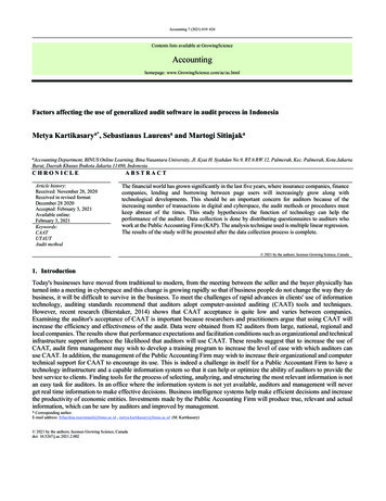
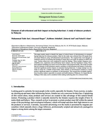
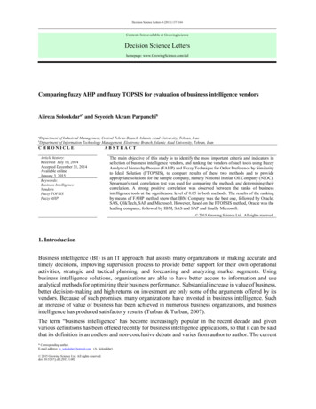
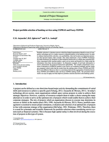
115P. Sharafi et al. / Engineering Solid Mechanics 6 (2018)ribs (Dawood et al., 2010) are two popular strengthening techniques being employed for improving themechanical performance of standard sandwich panels.This study proposes a new geometry design and material to enhance the properties of the foam-filledsandwich panels with regard to such failure modes. A 3-D high density Polyethylene (HDPE) sheetsare used as the skins with a thickness as 2 mm, and high-density PU foam is used as the core with atotal thickness as 100 mm, as illustrated in Fig. 1. Using the HDPE sheets, manufactured withapproximately 1200 studs per square meter, higher pull-out and delamination strength, as well as betterstress distribution, and buckling performance can be achieved. The studs also improve the resistanceof the face sheets and foam-core from debonding and increasing the interface strength between thefoam-core and the face sheets. This innovative sandwich panel was developed at the centre forinfrastructure engineering (CIE) in the Western Sydney University to be used as modular walls andfloors in rapid assembly buildings for semi-permanent post disaster housing.Fig. 1. Introduced sandwich panel with HDPE skins and PU foam-core2. Material characterizationThis section reports the detailed descriptions of the tests carried out for material characterization ofthe constituent materials i.e. PU rigid foam and 3-D HDPE skin sheets. To evaluate the basic materialproperties, in addition to using the manufacturers’ data, some experimental tests were performed.2.1 Polyurethane foam used in the sandwich panelPolyurethane high-density rigid foam with a density of 192 kg/m3 was selected for the core material,according to the results the preliminary finite element models. Table 1 shows the PU foam’smanufacturing and mechanical properties, provided by the manufacturer, and validated in thelaboratory according to the ASTM 1730 standard specification for rigid foam for use in structuralsandwich panel cores (Garrido et al., 2016; ASTM-E1730, 2015).Table 1. Mechanical and manufacturing properties of the selected PU rigid foamDensity(kg/m3)192Cream time35-40 secMechanical Properties of the PU foamCompressive yield strengthTensile yield strength(MPa)(MPa)3.511.896Manufacturing PropertiesGel timeTack free time94 4 sec115 5 secShear yield strength (MPa)1.034Free rise cup density280 – 300 kg/m3Using a uniaxial load machine (Fig. 2), three cubic specimens (dimensions: 50mm 50mm 50mm)were tested based on the ASTM E1730 and ASTM D1621 (ASTM-D1621, 2010) standards at a loadingrate of 5 mm/min in order to identify the structural properties of the rigid PU foam.
116Fig. 2. Uniaxial load test for determining the compressive behaviour of PU foamTable 2 shows the yield stress and elastic modulus for each specimen, and Fig. 3 illustrates the stressstrain curves in the elastic region and failure graph, respectively. The curves show that this type of PUfoam, which is made of a 100:110 weight ratio mixture of AUSTHANE POLYOL AUW763 andAUSTHANE MDI, can undertake considerable deformation before the failure. These stress-straincurves are relatively linear in the elastic region, with a yield region at an average stress of 3.51 MPa,and an average elastic modulus of 135.5 MPa.Table 2. Yield stress and elastic modulus of PU specimensTest 1Test 2Test 3Test 4Test 5AverageStandard Deviationσy (MPa)3.63.523.453.53.483.510.056E (MPa)130137.9132.9141.3136.7135.55.05Fig. 3. Results of the uniaxial load test on PU foam, left: total behaviour and right: elastic rangeThe yield behaviour can be explained by the buckling of the foam's internal walls. ScanningElectron Microscopic images (SEM), provided before and after compression test, shown in Fig. 4,substantiate such behaviour. A long and rather flat plateau was followed. Then, a densification(hardening) region was created by a gradual stress increase when the cell walls were stacked prior tofinal densification. In this range of loading, no visible signs of failure were observed. Residualdisplacement of the collapsed foam however, occurs once the unloading stage was complete.
117P. Sharafi et al. / Engineering Solid Mechanics 6 (2018)Fig. 4. Images from the scanning electron microscope on the PU specimens (a) before and (b) after the compression test.2.2 High density Polyethylene sheetsThe face sheets of the sandwich panels are made of 3-D HDPE (High Density Polyethylene) sheetsprimarily produced as a concrete embedment liner to provide protection from mechanical damage anda corrosive and erosive environment. In addition to resistance to chemical and environmental threats,its relatively high strength, and in particular its 3-D studded face with approximately 1200 studs persquare meter, can effectively contribute to the sandwich composites’ structural performance byproviding high pull out strength, minimum lateral movement of the skin, and stronger bonding. Fourdifferent thicknesses of the sheets were initially investigated (2mm, 3mm, 4mm and 5mm), and at theend the sheets with 2mm tackiness were selected for the sandwich composite. Table 3 shows somemechanical properties of the selected sheet, provided by the manufacturer and validated byexperimental tests in the laboratory, in accordance with the ASTM D5199, ASTM D1505 and ASTMD6693 provisions (ASTM-D6693, 2015) at a loading rate of 5 mm/min.Table 3. Specifications of the HDPE sheetsTested PropertyThickness (mm)Density (g/mm2)Sher strength at yield (MPa)Elongation at Break (%)Stud pull-out strength (kN/m2)Notched Constant Tensile Load, hoursCoefficient of Linear Thermal Expansion, per ⁰CLow Temperature Brittleness, ⁰CDimensional Stability, % (each direction)Water Absorption, %Test MethodASTM D 5199ASTM D 1505ASTM D 5397ASTM D 696ASTM D 746ASTM D 1204ASTM D 570Nominal value20.945.2500 6704001.20E-04-7710.1In order to identify the structural behaviour of the skin, in-plane tensile tests were conducted on twoprincipal perpendicular directions (lengthwise and crosswise) of the HDPE sheets, using a universalhydraulic testing machine. Five repeated specimens for each direction of the HDPE face sheet weretested as shown in Fig. 5. Typical tension specimens consisted of flat strips with a total width of 19 mmand a total length of 115 mm, according to ASTM D6693 standard (ASTM-D6693, 2015). Fig. 6 showsthe coupon test results. The 3-D HDPE sheets exhibited a relatively linear elastic response up to a strainof 0.15 mm/mm at the yield stress of 19.7 MPa in the lengthwise direction; and to a strain of 0.11mm/mm at the yield stress of 20.6 MPa in the transverse (crosswise) direction, indicating relativelysimilar behaviour in the elastic range. Since the coupon specimens were cut from 3-D panels, the minordifferences in behaviour could be due to the combination of the presence of the studs in differentdirections, or manufacturing homogeneity of the sheets. A non-linear plastic stress–strain relationshipwas observed in the higher ranges of strain. Results show the HDPE modulus of elasticity in lengthwise
118direction is EL 19.7 / 0.15 131.33 MPa, and in crosswise direction is EC 20.6 / 0.11 187 MPa. Inthe computer model average value of ESTUD 159 MPa is used to model the HDPE as isotropic material.Fig. 5. HDPE coupon test and specimens’ dimensionsFig. 6. HDPE coupon tests results for the Lengthwise and Crosswise directions
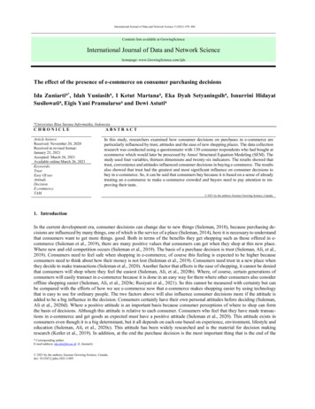
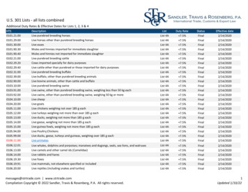
P. Sharafi et al. / Engineering Solid Mechanics 6 (2018)1193. Experimental ProgramGeneral speaking, the flexural stiffness of sandwich beams/panels can be calculated using First-orderShear Deformation Theory (FSDT) (Sharafi et al., 2012a, 2012b; Carlsson & Kardomateas, 2011). TheFSDT can also be used to estimate the shear stiffness of each sandwich beam type by fitting the resultscollected from four-point flexural tests. In this regard, a perfect bond must be assumed to exist betweenthe core and the facings. The bending stiffness can be computed accounting for the deflectioncomponents that are associated with bending and shear deformations (Sharafi et al., 2014a, 2014b;Hayes, 2003). This study examined the core shear properties of introduced polyurethane infill-foamcomposite panels subjected to flexure in such a manner that the applied moments produce curvature ofthe sandwich facing planes. Also, in this regard, core shear ultimate stress (Fsult), facing bending stress(σ), transverse shear rigidity (U) and core shear modulus (G) of introduced sandwich panel arecalculated based on ASTM C393/C393M (ASTM-C393/C393M, 2011) and ASTM D7250/D7250M(ASTM-D7250/D7250M, 2011) using six medium-scale sandwich specimens with 45cm length, 20cmwidth and 10cm as total thickness of composite section. The detailed descriptions of the tests carriedout on specimens which are four-point quarter-span loading and three-point mid-span loading flexuraltests (Fig. 7) are discussed in this section.Fig. 7. Four-point quarter loading and three-point mid span loading configurationsThe four-point bending test in accordance with ASTM C393/C393M under quarter point loadingconfiguration is performed for core shear ultimate stress (Fsult) and facing bending stress (σ)calculations. This test method is limited to obtaining the core shear strength or core-to-facing shearstrength, and to obtaining load-deflection data for use in calculating sandwich beam flexural and shearstiffness using practice D7250/D7250M. The test setup is illustrated in Fig. 8(a). An INSTRON testmachine (model no. 5500R) was used. High resistance rubber pads (with a Shore A durometer hardnessof 60, a nominal width of 25 mm and a nominal thickness of 3 mm) were inserted at the loading andsupporting points to distribute the load uniformly and reduce the stress concentrations. Three specimenswere investigated, where they were tested in one-way bending with the span of 400 mm, under twoequal point loads, applied at 100 mm from each support. The specimens have been inserted into the testfixture and then were aligned so that the longitudinal axis of the specimen was perpendicular (within1 ) to the longitudinal axes of the loading bars, and the bars were parallel (within 1 ) to the plane ofthe specimen facings. The specimens were loaded to failure at a displacement rate of 6 mm/min. Thebottom deflection at mid-span was recorded using a Linear Potentiometer (LP) having a minimumaccuracy of /-1%. A data acquisition system was used to record the load, displacement, and deflectionduring testing. In this study applied force versus crosshead displacement, and applied force versusdeflection data were recorded continuously. In addition, the visual method was used to determine anyinitial failure (Fig. 8 (b)).
120Fig. 8. (a) Four-point quarter-span loading flexural test setup; and (b) multi-mode of failure in the vicinity of the midspanThe applied force versus crosshead displacement and mid-span deflection are shown in Figs. 9 and 10,respectively.Fig. 9. The applied force versus crosshead displacement forfour-point quarter-span loading testFig. 10. The applied force versus mid-span deflection forfour-point quarter-span loading flexural test4. Calculation of core shear ultimate stress and facing bending stressIn this section, shear ultimate stress (Fsult) and facing bending stress (σ) of innovated sandwich panelare calculated using the typical cross section shown in Fig. 11; parameters and formulas based onASTM C393/C393M.Fig. 11. Sandwich panel thickness dimensions (ASTM-C393/C393M, 2011)
121P. Sharafi et al. / Engineering Solid Mechanics 6 (2018)The results and calculation of core shear ultimate stress and facing bending stress are summarized inTable 4.Table 4. Calculation of core shear ultimate stress and facing bending stress of innovated sandwich panelPmax(kN)Fsult(MPa)σ(MPa)Failure mode and location*Specimen 176.191.997.2Specimen 279.722101.7Specimen 371.951.891.8Average75.951.996.9Standard deviation3.890.15CV (%)5.125.25.2* (M)(G)(B/C): (Multi-mode)/(Gage)/( Bottom facing/Core) (ASTM-C393/C393M, The facing bending stress is calculated as a reference value at the maximum applied force. Sincethis test method is restricted to the core or core-to-facing shear failures, the facing stress does notrepresent the facing ultimate strength. To obtain the facing ultimate strength, the test method ASTMD7249/D7249M can be used (ASTM-D7249/D7249M, 2017). The results show that the foam core incomposite section, withstand twice shear stress as the bare foam material.5. Calculation of transverse shear rigidity and core shear modulusTransverse shear rigidity (U) and core shear modulus (G) of innovated sandwich panel can becalculated based on the results of the four-point quarter-span loading tests and a series of similar threepoint mid-span loading supplementary tests based on ASTM D7250/D7250M. The formulations forcalculating are presented in Table 5 (ASTM-D7250/D7250M, 2011).Table 5. Transverse shear rigidity and core shear modulus based on ASTM standardsLoading ConfigurationOne D7249/D7249M Standard 4-Point LoadingandOne 3-Point Mid-Span LoadingOne D7249/D7249M Standard 4-Point LoadingandOne 4-Point Third-Span LoadingOne D7249/D7249M Standard 4-Point LoadingandOne 4-Point Quarter-Span LoadingOne 3-Point Mid-Span LoadingandOne 4-Point Quarter-Span LoadingOne 3-Point Mid-Span LoadingandOne 4-Point Third-Span LoadingOne 4-Point Quarter-Span LoadingandOne 4-Point Third-Span LoadingTwo 3-Point Mid-Span LoadingU transverse shear rigidity (N)G core shear modulus (MPa) 1 beam mid-span deflection for configuration #1corresponding to force P1 (mm) 2 beam mid-span deflection for configuration #2corresponding to force P2 (mm)U(Transverse shear rigidity)G(Core shear 22-1)/4Δ1((P1S13Δ2/P2S23Δ1)-1)P1 applied force for configuration #1 (N)P2 applied force for configuration #2 (N)S1 length of support span for configuration #1(mm)S2 length of support span for configuration #2(mm)U(d-2t)/[(d-t)2b]According to ASTM D7250/D7250M transverse shear rigidity are calculated based on ten loaddeflection selective steps of the least maximum applied force regarding both loading configurations(Tables 6 and Fig. 12).
122Table 6. The least maximum applied forces and their related mid-span deflections.4-Point QuarterPmax76.1979.7271.95 (minimum)75.953.895.12Specimen 1Specimen 2Specimen 3AverageStandard deviationCV (%)Span Loading midspan21.922.419.121.11.88.423-Point Mid SpanPmax56.2352.54 (minimum)53.9854.251.863.5Loading midspan24.923.824.224.30.562.3Fig. 12. Selected load-displacement levels of four-point quarter (right) and three-point mid span (left) loadingconfigurationsThe results and calculation of transverse shear rigidity and core shear modulus are summarized inTables 7.Table 7. Transverse shear rigidity (U) and core shear modulus calculations (G)Step 1 (adjusting)Step 2Step 3Step 4Step 5Step 6Step 7Step 8Step 9Step 10 (main)Average over time3-PointP1 Mid Span 1 (mm)1.22.54.66.99.111.914.516.920.123.8LoadingS1 (mm)4004004004004004004004004004004-PointP2 0Quarter Span 2 (mm)0.823.55.37.49.71214.416.719.1LoadingS2 (mm)400400400400400400400400400400USTEP 00383500417000225700GSTEP 36. Numerical investigationNumerical simulations were carried out to find the non-linear behaviour of the sandwich panel andcompare with the experimental measurements of the flexural behaviour of the composite sandwichbeams. The simulations of the four-point static bending test of the composite sandwich, the FEmodelling was performed using ANSYS R15 where a quasi-static three-dimensional model has beendeveloped to simulate and predict the mechanical performance of the composite sandwich panel underbending. For FE modelling, the same dimensions, and the same loading rate (6 mm/min) wereconsidered as for the experimental program. The PU foam was meshed using Hexahedral dominant,Quadrilateral and Triangular meshing. The HDPE sheets were meshed using MultizoneHexahedral/prism with Quadrilateral and Triangular elements while the studs meshed using hexahedralelements (Sharafi, et al. 2015, 2017a, 2017b). The mechanical properties of the PU foam and the HDPEsheets, obtained from experiments, were used for calibrating the inputs.
P. Sharafi et al. / Engineering Solid Mechanics 6 (2018)1236.1 Flexural behaviourThe FE results show equivalent (Von-Mises) stress of foam has been concentrated at two stripsbetween loading effect points and supports and other areas are under very low stress. The first yieldingsymptom of foam occurs when the equivalent (Von-Mises) stress of foam reaches to manufactureminimum identified yielding stress (2.8 MPa). However, the real yielding stress occurs at 3.51 MPa.Fig. 13 shows Von-Mises stress-strain diagram of foam.Fig. 13. Equivalent (Von-Mises) stress – strain diagramof foamFig. 14. Equivalent (Von-Mises) stress – strain diagram ofStudlinerWith regard to the skins, by applying more pressure, equivalent (Von-Mises) stress of Studlinerreaches to yielding stress, where the maximum strain of Studliner is 0.048 mm/mm. Maximumequivalent stress appears at the edges of Studliner. In addition, shear stress at studs keeps increasing asthe applied load continues increasing. Fig. 14 shows Von-Mises stress-strain diagram of the skins.Then, as similar as experimental tests, at 60th second the model start to collapse and large deformation,debonding and demolition between foam and skins appear on the loading point until 70th second (Figs.15 - 18).Fig. 15. (a) Stress and (b) strain of composite panel at collapsing modeFig. 16. Large deformation and debonding between the skin and foam core at collapsing mode
124Fig. 17. Large deformation and debonding of Studlinerat collapsing modeFig. 18. Large deformation and maximum strain ofcomposite panel just before collapseBy applying more pressure to the specimens, the ultimate fracture occurs on the mid-span at themaximum deflection point. The fracture profile is shown in Fig. 19.Fig. 19. The fracture profile and maximum deflection at mid-span of composite panel.Fig. 20 shows maximum Von-Mises stress-strain diagram of the composite panel. As it can be seen,in elastic range (as strain 2%) the composite panel has a semi linear demeanour but, after yieldingpoint shows a hyper elastic behaviour.
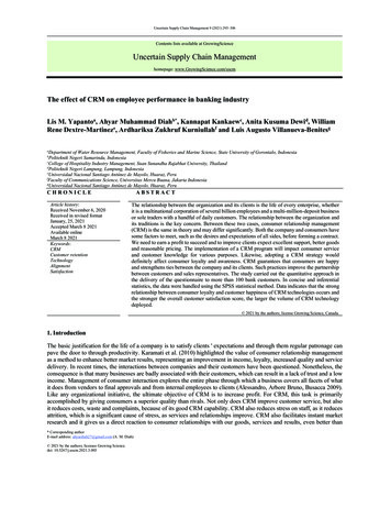
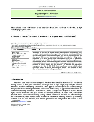
P. Sharafi et al. / Engineering Solid Mechanics 6 (2018)125Fig. 20. Equivalent (Von-Mises) maximum stress – strain diagram of composite panelResults indicate that under flexure, the foam core and skins displacement are in sync, whichdemonstrate well integrated behaviour of the introduced composite panel, as shown in Fig. 21 and Fig.22.Fig. 21. Homologous deflection of Studliner skins and foam coreFig. 22. Sync behaviour of maximum mid-span displacement of the skin and foam in time6.2 Shear BehaviourXY component of shear stress has a uniform distribution on the skin and core, which demonstratesthe good performance of skin studs in shear transfer. When the XY component of shear stress reachesto yielding point at both of core and skin, maximum XY shear component occurs at edges of the skinand core, under loading point. In addition, there is not any shear concentration in the skin studs on XYplane. YZ component of shear stress has a uniform distribution on the skin and core. This componenthas a strip of concentration at the loading line on the surface of the core as well as surface and body ofthe foam core. These strips continue toward supports in foam core. The YZ component of shear stress
126reaches to yielding point at both the core and skin, where there is not any shear concentration at studsof skin on the YZ plane.Fig. 23. Distribution of component of shear stress on the skin and foam core at collapsing modeThe distribution of XZ component of shear stress on the skin is as similar as XY component. Thedistribution of this component on studs is completely uniform. Maximum XZ shear component occursat the edges of skin. The XZ component of shear stress on the core has some local concentration and atother areas has a very low intensity. The XZ component of shear stress reaches to yielding point at bothof foam and the skin. These distributions are illustrated in Fig. 23. As shown in Fig. 24, results indicatethat the XY component of shear stress show relatively linear behaviour at low strains ( 2%) andnonlinear behaviour at higher amounts. The diagram of YZ component of shear stress-strain is linear.In addition, the XY component of shear stress show nonlinearity with a positive slope until collapsingmode.Fig. 24. Schematic stress-strain diagrams of XY, YZ and XZ component of shear at composite panel7. ConclusionFoam filled sandwich panels are one of the most popular and widely investigated types of compositestructures. In this study an innovative sandwich panel comprising 3D-HDPE skin layers and a highdensity foam core was proposed and the flexural and shear behaviour was investigated by experimentaland numerical research. The results showed that using 3D skins with 1200 studs per square meter, the
P. Sharafi et al. / Engineering Solid Mechanics 6 (2018)127composite sandwich panels resulted in a strong and stable composite section than individual sandwichsections alone. Results of the quasi-static three-dimensional model and the material nonlinearsimulations of the sandwich panels also indicate that under flexure, the foam core and s
P. Sharafi et al. / Engineering Solid Mechanics 6 (2018) ribs (Dawood et al., 2010) are two popular strength 115 ening techniques being employed for improving the mechanical performance of standard sandwich panels. This study proposes a new geometry design an d material to enhance the pr operties of the foam-filled