Transcription
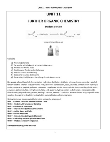
ENGINEERING GRAPHICS(Engineering Drawing is the language of Engineers)UNIT 1Conic Section (Ellipse, Parabola & Hyperbola) Cycloids, epicycloids,hypocycloids & Involutes around circle and square – scales – diagonal – vernierscale – Free hand sketchingDefinition: Engineering graphical language for effective communication among engineers whichelaborates the details of any component, structure or circuit at its initial drawing throughdrawing.The following are the various drafting tools used in engineering graphics. Drawing BoardMini drafter or T- squareDrawing Instrument boxDrawing PencilsEraserTemplatesSet squaresProtractorScale SetFrench curvesDrawing clipsDuster piece of cloth (or) brushSand-paper (or) Emery sheet blockDrawing sheet
Drawing board and mini drafterAbove figure shows drawing board and mini drafter. A mini drafter is a drafting instrumentwhich is a combination of scale, protractor and set square. It is used for drawing parallel,perpendicular and angular at any place in the drawing sheet.Divider and compassPro-circle
Set squaresSizes of drawing sheetThe table shows the designation of drawing sheet and its size in millimeter.DesignationDimension, mm Trimmed sizeA0841 x 1189A1594 x 841A2420 x 594A3297 x 420A4210 x 297
Method of dimensioning for circle, arc, semicircle:Φ – diameterR - radius
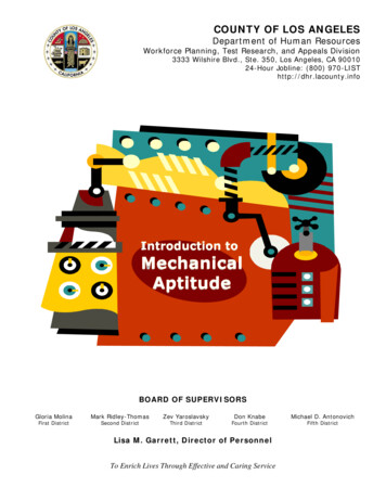
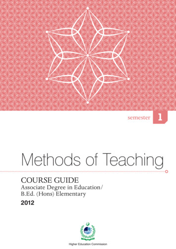
CONIC SECTIONSThe figure 1 shows the terminologies used in engineering graphics for acone. Generators are the lines which are assumed that they are present onthe surface of cone. These lines are called as “generators”, because it isgenerated by the user.Figure 11. When the cutting plane cuts the cone parallel to its base then the shape obtained will be acircle.2. When the cutting plane BB is inclined to the axis of the cone and cuts all the generators on oneside of the apex, the section obtained is an Ellipse
3. When the cutting plane CC is inclined to the axis of the cone and parallel to one of thegenerators, the section obtained is a Parabola4. When the cutting plane DD makes a smaller angle with the axis than that of the angle made bythe generator of the cone, the section obtained is a Hyperbola.Construction of conic curves by eccentricity method
Eccentricity is defined as the ratio between distance of vertex from focus and distance of vertexfrom the directrix.Important HintsIf e 1, curve obtained is EllipseIf e 1, curve obtained is ParabolaIf e 1, curve obtained is Hyperbola
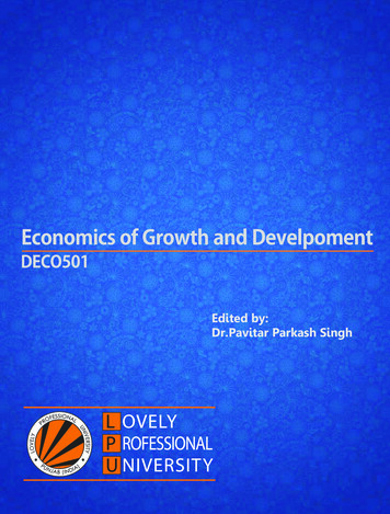
SOLVED EXAMPLESCONIC SECTIONS1. The focus of a conic is 30 mm from directrix. Draw the locus of a point P moving in sucha way that eccentricity is 2/3. Also draw a tangent and normal at any point on the curve.
Procedure to find number of divisions and size of each divisionGiven,Eccentrici ty 23Number of division Numerator value Denominator Value 2 3 5 divisionsSize of each divison 30 6 mm5Procedure :1. Draw the directrix.2. Draw a horizontal (axis) line perpendicular from a point C on directrix.3. Mark a point F (Focus) at a distance on the horizontal line at a distance of 30 mm fromdirectrix.4. Mark a point A (Vertex) by leaving two divisions from focus (each of size 6 mm) and thename the divisions as 1 and 2. Mark the remaining three divisions from A.5. Draw a vertical line from A, so that AX is equal to FA.6. Draw a line joining C and X and extend it in the same angle and direction.7. After focus mark the points 3,4,5 etc. so that each division is of 6 mm.8. Draw vertical lines crossing the points 1,2,3,4,5 etc.9. Mark the points 1’, 2’, 3’ etc., on the inclined line.10. With 1-1’ as radius F as centre draw the arcs above below the horizontal line on the line 1-1’and name the points as P1’ and P1 respectively.11. Follow the same procedure and mark the points P 2’ and P2 and so on.12. Join all the points with a single stroke smooth curve to get an ellipse.Procedure to draw tangent and normal1. Mark a point P on the ellipse.2. Join P and F.3. Draw a perpendicular to the line PF till the line meets the directrix at the point T4. Join the points T and P for getting a tangent for the ellipse.5. Keep the protractor parallel to the line TP and draw the perpendicular line from P for getting anormal.
2. The distance of focus for a conic curve from directrix is 30 mm. Draw the locus of apoint P so that the distance moving point from directrix and focus is unity.Procedure to find number of divisions and size of each divisionEccentrici ty 11Number of division Numerator value Denominator Value 1 1 2 divisionsSize of each divison 30 15 mm2
Procedure :1. Draw the directrix d-d’.2. Draw a horizontal (axis) line perpendicular from a point C on directrix.3. Mark a point F (Focus) at a distance on the horizontal line at a distance of 30 mm fromdirectrix.4. Mark a point A (Vertex) by leaving two divisions from focus (each of size 6 mm) and thename the divisions as 1 and 2. Mark the remaining three divisions from A.5. Draw a vertical line from A, so that AX is equal to FA.6. Draw a line joining C and X and extend it in the same angle and direction.7. After focus mark the points 3,4,5 etc. so that each division is of 6 mm.8. Draw vertical lines crossing the points 1,2,3,4,5 etc.9. Mark the points 1’, 2’, 3’ etc., on the inclined line.10. With 1-1’ as radius F as centre draw the arcs above below the horizontal line on the line 1-1’and name the points as P1’ and P1 respectively.11. Follow the same procedure and mark the points P 2’ and P2 and so on.12. Join all the points with a single stroke smooth curve to get a parabola.Procedure to draw tangent and normal1. Mark a point P on the ellipse.2. Join P and F.3. Draw a perpendicular to the line PF till the line meets the directrix at the point T4. Join the points T and P for getting a tangent for the ellipse.5. Keep the protractor parallel to the line TP and draw the perpendicular line from P for getting anormal.3. Draw a hyperbola whose distance of focus from directrix is 60 mm. The eccentricity is3/2. Also draw a tangent and normal at any point P on the curve.32Number of division Numerator value Denominator ValueEccentrici ty 3 2 5 divisionsSize of each divison 30 6 mm5
Procedure:1. Draw the directrix d-d’.2. Draw a horizontal (axis) line perpendicular from a point C on directrix.3. Mark a point F (Focus) at a distance on the horizontal line at a distance of 30 mm fromdirectrix.4. Mark a point V (Vertex) by leaving two divisions from focus (each of size 6 mm) and thename the divisions as 1 and 2. Mark the remaining three divisions fromV.5. Draw a vertical line from V, so that VA is equal to FV.6. Draw a line joining C and A and extend it in the same angle and direction.7. After focus mark the points 3,4,5 etc. so that each division is of 6 mm.8. Draw vertical lines crossing the points 1,2,3,4,5 etc.
9. Mark the points 1’, 2’, 3’ etc., on the inclined line.10. With 1-1’ as radius F as centre draw the arcs above below the horizontal line on the line 1-1’and name the points as P1’ and P1 respectively.11. Follow the same procedure and mark the points P2’ and P2 and so on.12. Join all the points with a single stroke smooth curve to get a hyperbola.Procedure to draw tangent and normal1. Mark a point P on the hyperbola.2. Join P and F.3. Draw a perpendicular to the line PF till the line meets the directrix at the point T4. Join the points T and P for getting a tangent for the ellipse.5. Keep the protractor parallel to the line TP and draw the perpendicular line from P for getting anormal.PROBLEMS FOR PRACTICE1. A fixed point F is 7.5 cm from a fixed straight line. Draw the locus of a point P moving insuch a way that its distance from the fixed straight line is 2/3 times the distance from focus.Name the curve. Draw the tangent and normal at any point on the curve.2. Draw the path traced by a point P moving in such a way that the distance of the focus fromdirectrix is 40 mm. The eccentricity is unity.3. A point moves such that its distance from a fixed straight line to its distance from a fixed pointis equal. Draw the locus of the curve traced by that point. Add a normal and tangent to the curveat 40mm above the axis4. Draw an ellipse when the distance of focus from the directrix is equal to 35 mm andeccentricity is 3/4. Draw a tangent and normal at a point P located at 30mm above the major axis.5. Draw an ellipse whose focus distance from is 70 mm and e is 0.5. Draw the tangent andnormal 40 mm above the axis.6. Draw hyperbola whose distance of focus is 55 mm and e 1.5. Draw the tangent and normal50 mm from the directrix.
CYCLOIDSCycloid : It is a curve traced by a point on the circumference of a circle which rolls along astraight line without slipping.Epicycloid : It is a curve traced by a point on the circumference of a circle which rolls outsideanother circle.Hypocycloid : It is a curve traced by a point on the circumference of a circle which rolls insideanother circle.SOLVED EXAMPLES1. A circle of diameter 50 mm rolls on a straight line without slipping. Trace the locus of apoint on the circumference of the circler rolling for one complete revolution. Name thecurve, draw the tangent and normal at any point on the curve.Procedure :1. Draw a circle of diameter 50 mm.2. Divide the circle into 12 equal parts, by taking an angle of 30o each.3. Name the divisions as 1,2,3 in anticlock wise direction from the division next to the bottommost one.4. Name the bottom most division as P.5. Draw a horizontal line as a tangent from P, for a length of L πd, where d is diameter ofcircle.6. Divide the horizontal line into 12 equal divisions and the name the points as 1’, 2’, 3’, etc.7. Draw lines passing through 11 and 1, 10 and 2, 8 and 3 and so on.8. Draw vertical lines from 1’, 2’, 3’, etc., so that they meet the horizontal line from 9.9. Name the meeting points as C1, C2, C3, etc.
10. With C1 as centre 25 mm (radius of circle) as the radius, draw the arc on the horizontal linedrawn from 1. Name the cutting point as P1.11. Follow the same procedure and get the points P2, P3,P4, etc.12. Join all the points with a single stroke smooth curve to get a cycloid.Procedure to draw a tangent and normal to a cycloid1. Mark a point A on the cycloid.2. With A as centre, 25 mm as the radius draw an arc on the horizontal line drawn from 9.3. Name the cutting point as C.4. Draw a perpendicular line from C to the horizontal line drawn from P.5. Name the cutting point as B.6. Join B and A, which will be the normal to cycloid7. Keep the protractor parallel to the line BA and draw a perpendicular line from P, which will bethe tangent to cycloid.2. Draw epicycloid of a circle of 40 mm diameter, which rolls outside on another circleof 150 mm diameter for one revolution clockwise. Draw a tangent and normal to itat a point 95 mm from the center of the directing circle.
To calculate θ:r 360Rwhere, r radius of rolling circleR radius of directing circle20 36075 98 Procedure :1. Mark a point O’.2. With O’ as centre draw a sector ((O’PA) with radius of generating circle 75 mm for an angle of 98o.3. Extend the line from P for a distance of 20 mm (radius of rolling circle) and the mark the point O at theend.4. With O as centre, draw the rolling circle of diameter 20 mm.5. Divide the circle into 12 equal parts and name the points as 1,2,3.etc., in the anticlockwise directionfrom the point next to the bottom most one.6. With O’ as centre, draw the arcs passing through the points 11-1, 10-2, 9-3 etc.7. Divide the sector in to 12 equal angles and draw the lines starting from O’.8. Mark the cutting points of the lines on the arc starting from 3-9, as O1, O2 etc.9. O1 as centre, 20 mm as radius draw an arc on the curve drawn from 11. Name the cutting point as P 1.10. Similarly mark the other points P 2,P3,P4,. etc.11. Join all the points by a smooth curve to get a hypocycloid.
3. Draw hypocycloid of a circle of 40 mm diameter, which rolls inside of another circle of160 mm diameter for one revolution counter clockwise. Draw a tangent and normal to itat a point 65 mm from the center of the directing circle.Calculation :r 360Rwhere, r radius of rolling circleR radius of directing circle20 36080 90
Procedure :1. Mark a point O’.2. With O’ as centre draw a sector (O’PA) with radius of generating circle 80 mm for an angle of 98o.3. Mark P on the line PO’ so that OP radius of rolling circle.4. With O as centre, draw the rolling circle of diameter 20 mm.5. Divide the circle into 12 equal parts and name the points as 1,2,3.etc., in the clockwise direction fromthe point next to the top most one.6. With O’ as centre, draw the arcs passing through the points 11-1, 10-2, 9-3 etc.7. Divide the sector in to 12 equal angles and draw the lines starting from O’.8. Mark the cutting points of the lines on the arc starting from 3-9, as O1, O2 etc.9. O1 as centre, 20 mm as radius draw an arc on the curve drawn from 11. Name the cutting point as P 1.10. Similarly mark the other points P 2,P3,P4,. etc.11. Join all the points by a smooth curve to get an epicycloid.PROBLEMS FOR PRACTICE1. Draw epicycloids of a circle of 40 mm diameter, which rolls outside on another circle of 150mm diameter for one revolution clockwise. Draw a a tangent and normal to it at a point 95 mmfrom the center of the directing circle.2. Draw hypocycloids of a circle of 40 mm diameter, which rolls inside of another circle of 160mm diameter for one revolution counter clockwise. Draw a a tangent and normal to it at a point65 mm from the center of the directing circle.3. A roller of 40 mm diameter rolls over a horizontal table without slipping. A point on thecircumference of the roller is in contact with the table surface in the beginning till one end ofrevolution. Draw the path traced by the point.
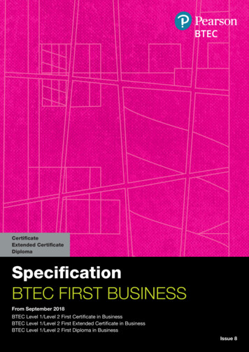
INVOLUTEDefinition : Involute is a path traced a point at the end of the string when it is wound orunwound from a cylindrical drum, cuboid or any tubular object.SOLVED EXAMPLES1. Draw an involute of a circle of 50mm diameter. Also, draw a tangent and normal at anypoint on the curve.Procedure :1. Draw a circle of diameter 50 mm.2. Divide the circle into 12 equal parts and mark the names 1,2,3, etc., in clockwise directionstarting from a point next to the bottom most one. Mark the centre point of the circle as O.3. Draw a tangent AC from point 12 for a length of L πd, (d – diameter of circle).4. Divide AC into 12 equal points and the name points 1’,2’,3’.etc.,5. Draw tangents from 1, 2, 3, etc., as shown in figure.6. With 11-11’ as radius 11 as centre cut an arc on the tangent drawn from 11 and name the pointas P11.7. Similarly obtain other points P10, P11, .etc.,8. Join all the points by a smooth curve to obtain an involute.
Procedure to draw a tangent and normal to an involute :1. Mark a point N on the involute.2. Join N and O. With the midpoint of ON as centre, half of ON as the radius, draw a semicircleon the opening side of the involute.3. Mark the cutting point of the semicircle and circle as M.4. Join M and N, which will be the normal.5. Keep the protractor parallel to MN and draw a perpendicular from N, to draw the tangent.2. An inelastic string 155 mm long has one stone end attached to the circumference of acircular disc of 40 mm diameter. Draw the curve traced out by the end of the string, whenit is completely wound around the disc keeping it always tight (wound method)Hints : Draw a line 12-P tangent to 12. Divide the line 12 equal parts only for a distance of L πd (d –diameter of circle).Mark the same divisions after that till p.Follow the same procedure with the starting radius of 12-14 with 1’ as centre.The involute will be closed after 12’, since the length of chord is more than circumference of thecircle.
Tutorial: (Students are requested to refer the book and write the procedure for problem 3)3. Draw the path traced by a point at the end of a string, when it is wound around a square of size40 mm.
PROBLEMS FOR PRACTICE1. Draw the path traced by the end of a string when it is wound around a cylindrical drum ofdiameter 40 mm.2. Draw an involute around a hexagon of side 25 mm.ORTHOGRAPHIC PROJECTION ORTHO means Right-angle. GRAPHIC means Drawing. ORTHO GRAPHIC means Right-angled Drawing.How to draw the front view (elevation) and top view (plan) in first angle projection?
Obtaining right side view on left of the object in first angle projectionSymbol for I angle and III angle projection
Example 1 : Draw the elevation, plan and left side view of the rectangle shown in the figure.AnswerExample 2 : Draw the elevation and plan of the block given below.Example 2 : Draw the elevation and plan of the block shown below.Answer
Example 3 : Draw the elevation, plan and left end view of the object shown below.AnswerExample 4: Draw the front view, top view and left side view of the block shown below.Answer
Example 5: Draw the front, top and right end view of the block shown below.AnswerExample 6: Draw the elevation, plan and right side view of the object.Answer
Example 7 : Draw the elevation, plan and right side view.Answer8. Draw the plan, elevation and left end view of the block shown below.Answer
PROBLEMS FOR PRACTICE1. Draw the elevation, plan and left end view of the block shown below.2. Draw the elevation, plan and left side view of the object given below.
3. Draw the front, top and left side view of the block shown below.4. Draw the plan, elevation and right end view of the object shown below.
5. Draw the front view, top view and right side view of the block shown below.SCALESIntroductionWhat is a scale?It is not always possible or convenient to draw drawings of an object to its actual size. Forinstance, drawings of very big objects like buildings, machines etc., cannot be prepared in fullsize because they would be too big to accommodate on the drawing sheet.Drawings of very small objects like precision instruments, namely, watches, electronic devicesetc., also cannot be prepared in full size because they would be too small to draw and to read.Therefore a convenient scale is always chosen to prepare the drawings of big as well as smallobjects in proportional with smaller or larger sizes. So the scales are used to prepare a drawing ata full size, reduced size or enlarged size.Definition :Scale is defined as the ratio of the linear dimension of an element of an object as represented inthe original drawing to the linear dimension of the same element of the object itself.
Full size scaleIf we show the actual length of an object on a drawing, then the scale used is called full sizescale.Reducing scaleIf we reduce the actual length of an object so as to accommodate that object on drawing, thenscale used is called reducing scale. Such scales are used for the preparation of drawings of largemachine parts, buildings, bridges, survey maps, architectural drawings etc.Enlarging scaleDrawings of smaller machine parts, mechanical instruments, watches, etc. are made larger thantheir real size. These are said to be drawn in an increasing or enlarging scale.Note: The scale of a drawing is always indicated on the drawing sheet at a suitable place eitherbelow the drawing or near the title thus “scale 1:2”. Representative Fraction (R.F)The ratio of the drawing of an object to its actual size is called the representative fraction, usuallyreferred to as R.F.R.F Drawing of an object/ Its actual size (in same units)For reducing scale, the drawings will have R.F. values of less than unity.For example, if 1 cm on drawing represents 1 m length of an object,1cm(1 100 cm)1R.F 1100R.F For drawings using increasing or enlarging scale, the R.F values will be greater than unity.For example, when 1 mm length of an object is shown by a length of 1cm on the drawing, thenR.F 1 10 10 11 mm 1
The engineering scales recommended by BIS (Bureau of Indian Standards) are as followsTypes of Scales1. Simple scales2. Diagonal scales3. Vernier scalesPlain ScaleA plain scale is simply a line, which is divided into a suitable number of equal parts, the first ofwhich is further sub-divided into small parts. It is used to represent either two units or a unit andits fraction such as km, m and dm, etc.Example 1: Construct a plain scale to show meters when 1cm represents 4 meters and longenough to measure up to 50 metres. Find the R.F. and mark on it a distance of 36 meters.Procedure:Drawing size1cm1 Actual size (in same units) (4 100 cm) 4002. Length of scale R. F M aximum length to be measuredM aximum length to be measured 50 m.1. R.F 1 1 Therefore length of scale, L 50 m 50 100 cm 12.5 cm 400 400 3. Draw a horizontal line of length 12.5 (L).4. Draw a rectangle of size 12.5 0.5 cm on the horizontal line drawn above5. Total length to be measured is 50m.therefore divide the rectangle into 5(n) equal divisions,each division representing 10 m.
6. Mark 0 at the end of the first main division.7. From 0, number 10, 20, 30 and 40 at the end of subsequent main divisions towards right asshown.8. Then sub-divide the first main division into 10 subdivisions to represent metres (usinggeometrical construction).9. Number the sub-divisions i.e. metres to the left of 0 as shown.10.Write the names of main units and sub-units (METRES) below the scale. Also mentionthe R.F. as shown.11. Indicate on the scale a distance of 36metres [ 3main divisions to the right side of 0 6subdivisions to the left of 0 (zero)]Example 2 : Construct a plain scale of R.F. 1:50,000 to show kilometers and hectometersand long enough to measure upto 7 kilometres. Measure a distance of 54 hectometers onyour scale.Procedure: 1 1. Length of scale 7 km 7 1000 100 cm 14 cm 50000 2. Draw a rectangle of size 14cmx0.5cm.divide the rectangle into 7 equal divisions, eachrepresenting 1km or 10 hm.3. Mark 0 at the end of first main division and 1,2,3 6 at the end of subsequent main divisionstowards right. Sub-divide the first division into 10 sub-divisions, each representing 1 hm.Number the sub-divisions to the left of 0 (zero).
Example 3 : A room of 1000 m3 volume is represented by a block of 125 cm3 volume. FindR.F. and construct a plain scale to measure upto 30 m. Measure a distance of 18 m on thescale.Procedure:1. 125 cm3 1000 m3 (given) i.e. 5 cm 10 m.1cm1 (2 100 cm) 20013. Length of the scale, L 30 100 15 cm2002. Therefore R.F Note: While doing problems on volume /area, change the units of volume/area into thecorresponding linear measures in order to find the length of the scale to construct the plain scale.Diagonal ScalesPlain scales are used to read lengths in two units such as metres and decimeters or to read theaccuracy correct to first decimal. Diagonal scales are used to represent either three units ofmeasurements such as metres, decimeters, centimeters or to read to the accuracy correct to twodecimals.Principle of Diagonal ScaleIt consists of a line divided into required number of equal parts. The first part is sub-divided intosmaller parts by diagonals.1. Draw vertical lines at A and B. Divide AD into ten equal divisions of any convenientlength (say 5cm) and complete the rectangle ABCD.2. Join the diagonal AC.
3. Draw horizontal lines through the division points to meet AC at 1’, 2’, 3’, 4’, 5’, & 6’.4. Consider the similar triangles ADC and A88’. 88’/DC A8/AD; but A8 8/10 AD.Therefore 88’/DC 8/10 i.e. 88’ 8/10 DC 0.8 DC 0.8 AB.5. Thus the horizontal lengths 11’,22’, 33’ etc. are equal to 0.1 AB, 0.2 AB, 0.3 AB etc.respectively, i.e. the horizontal line below CD becomes progressively shorter in length by1/10 CD. This principle is used in constructing the diagonal scaleExample 4: Construct a diagonal scale of R.F. 1:32,00,000 to show kilometers and longenough to measure upto 400 km. Show distances of 257 km on your scale.
Procedure :1. R.F. 1:32,00,000 (Given).2. Length of the scale R.F Maximum distance to be measured 1 400 km32000001 400 1000 100 cm 12.5 cm32000003. Draw a line PQ of 12.5 cm long.4. Maximum length to be measured is 400 km. Minimum distance to be measured 1 km257(which is obtained from datakm)333Maximum distanceTherefore 400. This can be obtained in 3 stepsas 4 10 10Minimum distance5. Therefore by geometrical construction divide PQ into 4 main divisions, each main divisionrepresenting 100 km. Mark 0 (zero) at the end of the first main division. Also mark 100, 200 and300 towards the right of zero.6. Using geometrical construction sub-divide the main division into 10 sub-divisions, eachrepresenting 10 km. To avoid crowding of numbers, mark only 50,100 towards the left of zero.7. Draw a line PS of 5cm long perpendicular to PQ.8. Complete the rectangle PQRS and draw vertical lines from each main division on PQ.9. Divide PS into 10 equal divisions and name the divisions as 0,1,2,3 10 from P to S.10. Draw horizontal lines from each division on PS.11. Join S to the first sub-division from P on the main scale PQ.Thus the first diagonal line isdrawn.12. Similarly draw the remaining 9 diagonals parallel to the first diagonal. Thus each 10 kmis divided into 10 equal parts by diagonals.
Example 5: The distance between Coimbatore and Madurai is 200 km and its equivalentdistance on the map measures 10 cm. Draw a diagonal scale to indicate 223 km and 135km.Procedure:1.10 cm on the map represents200 km. So R F 10 cm2000000200 km2.So, take the length of the scale as 12.5 cm to represent the actual distance3. M ax 250 km; M in 1 km;12.5 cm 200 km 250 km10 cmM ax 250 5 5 10MinVernier ScalesLike diagonal scales, vernier scales are used to read very small units with accuracy. They areused, when a diagonal scale is inconvenient to use due to lack of space. A vernier scale consistsof two parts, i.e., Main scale and a vernier. The main scale is a Plain scale divided into minordivisions.The vernier is also a scale used along with the main scale to read the third unit, which is thefraction of the second unit on the main scale.Least count: Least count the smallest distance that can be measured accurately by the vernierscale and is the vernier scale and is the difference between a main scale division and a vernierscale division.Types of Verniers:1. Forward vernier or direct vernier2. Backward vernier or retrograde vernier
Backward / Retrograde VernierIn this type, the markings on the vernier are in a direction opposite to that of the main scaleand (n 1) main scale divisions are divided into n vernier scale divisions.Example 6: Construct a vernier scale to read meters, decimeters and centimeters and longenough to measure upto 4 m. R F of the scale is 1/20. Mark on your scale a distance of2.28 m.Procedure:1. Least count: It is required to measure metres, decimeters and centimeters, i.e., the smallestmeasurement on the scale is cm. Therefore, L.C . smallest distance to be measured 1cm 0.01m. 1 2. Length of the scale R F maximum distance to be measured 4 cm 20 3. Main scale : Draw a line of 20 cm length. Complete the rectangle of 20 cm 0.5 cmand divide this into 4 equal partseach representing1metre.Sub divide each part into10 main scale divisions.1m.s.d 1m 1dm10
To construct the vernier to centimeter:4. Take1division on the main scale and divide it into10 equal partson the vernier scale by11M.S.D 11 1dm105. Mark 0,55,1106 towards the left from 0on the vernier scale as shown.6. Name the units of the main divisions, sub-divisions and vernier divisions on the figure asshown.7. 2.28 m (V.S.D x 8) (M.S.D x14) (0.11 m x 14) 90.88 1.4) m.geometrica l construction. So 1 V.S.D References K.V, Natarajan, Engineering graphics, Dhanalakhshmi Publications, 2012. Venugopal, Engineering graphics, New age international, 2010.
5. Draw a vertical line from A, so that AX is equal to FA. 6. Draw a line joining C and X and extend it in the same angle and direction. 7. After focus mark the points 3,4,5 etc. so that each division is of 6 mm. 8. Draw vertical lines crossing the points 1,2,3,4,5 etc. 9. Mark the points 1', 2', 3' etc., on the inclined line. 10.