Transcription
TopCon devices Error listFor HMI / TC.RCU and Software TopControlV11.51
1TopCon – Error list1. General information 2021 Regatron AGThis document is protected by copyright.All rights, including translation, re-printing and duplication of this manualor parts of it, reserved. No part of this work is allowed to be reproduced,processed, copied or distributed in any form, also not for educationalpurposes, without the written approval of Regatron.This information in this documentation corresponds to the developmentsituation at the time of going to print and is therefore not of a bindingnature. Regatron AG reserves the right to make changes at any time forthe purpose of technical progress or product improvement, withoutstating the reasons. In general we refer to the applicable issue of our“Terms of delivery”.2 / 752021-08-17
1TopCon – Error listIdentificationManufacturerInformation on the manufacturerRegatron AGFeldmuehlestrasse 509400 RorschachSWITZERLAND 41 71 846 67 44www.regatron.comsupport@regatron.comTab. 1InstructionsDocument identificationIdentifierTopCon devices Error listError list VersionV11.51Tab. 2Open questionsIn you have any questions, your TopCon sales partner will be pleasedto be of assistance.3 / 752021-08-17
1TopCon – Error listTable of contents1.GENERAL INFORMATION . 2Identification . 3Manufacturer . 3Instructions . 3Open questions . 32.ERROR LIST . 52.1.Introduction . 52.2.Overview of group error codes and group warning codes . 72.3.Error group . 92.3.1.0) Internal . 92.3.2.1) Internal (PDSP) . 112.3.3.2) Output current . 142.3.4.3) Output voltage . 162.3.5.4) Supply . 182.3.6.5) Temperature . 222.3.7.6) Communication . 242.3.8.7) Internal (Modulator) . 272.3.9.8) Internal (AD overrange 1) . 302.3.10.9) Internal (AD overrange 2) . 322.3.11.A) Internal (AD underrange 1). 342.3.12.B) Internal (AD underrange 2). 362.3.13.C) Login. 382.3.14.D) Configuration . 442.3.15.E) Configuration 2 . 472.3.16.F) Miscellaneous . 492.3.17.G) IBC System . 522.3.18.H) IBC Supply . 532.3.19.J) IBC Communication . 532.3.20.K) IBC Power . 542.3.21.L) IBC Inverter . 552.3.22.M) IBC Miscellaneous . 572.3.23.N) IBC Inverter 2 . 582.3.24.Q) Configuration 4 . 592.3.25.R) Miscellaneous 2 . 622.3.26.S) Supply 2. 642.3.27.T) Login 2 . 652.3.28.U) Configuration 3 . 672.3.29.V) Communication 3 . 712.3.30.W) Internal 2. 742.3.31.X) Communication 2 . 754 / 752021-08-17
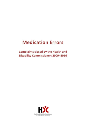
TopCon – Error list2Error list2. Error list2.1. IntroductionDivision into group and detail errorsTo be able to troubleshoot errors as quickly and accurately as possible,the possible errors are divided into 16 group errors. Each of thesegroup errors is in turn broken down into 16 detail errors.The group and detail errors can be identified by direct digital access (viaTopControl or HMI/RCU). Group errors and detail errors are alsoindicated sequentially on the front panel via a flashing code on the red“ERROR” light emitting diode.There is the same mechanism for warnings. They are indicated on thefront panel via the yellow “STATUS” light emitting diode or can bepolled via TopControl and HMI/RCU.Acknowledging an errorOn the occurrence of an error, the device remains in the ERROR stateuntil the error is acknowledged and the device signals this statecorrespondingly with the digital outputs (relay) and the light emittingdiodes on the front panel.The positive edge on the Clear Error signal is used to acknowledge anerror. The digital input provided for this purpose or the related controlparameter (direct digital access) is used.Control signals in case of an errorPower upClear ErrorVoltage ONClearingOutputvoltageStateError248124Fig. 1 Control signals in case of an error.Errors and acknowledgingThe warnings are also saved until they are acknowledged. The positiveedge of the Clear Error signal is used for this purpose.Errors can also be acknowledged via the TopControl application and viathe HMI/RCU.5 / 752021-08-17
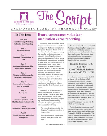
TopCon – Error list2Error listError and warning indication on the front panel LEDsThe number of flashes indicates the possible reasons for themalfunction (group error and detail error). The following illustrationshows a period in the indication cycle.1s0.2s2sStart1.5s0.2s123Group error codenG1sBreak 12345nDBreak StartDetail error codeErrors are indicted via the red ERROR LED; warnings via the yellowSTATUS LED.Error codes and warning codes are identical. All errors and warningsare output one after the other based on the scheme above. Then theflashing sequence starts again with the first error or first warning.The chapter lists all flashing codes and provides information on thereason for the error and how to rectify it.6 / 752021-08-17
TopCon – Error list2Error list2.2. Overview of group error codesand group warning codesIndication of the reason for the 02122232425262728293031321) ErrorgroupsPage0) Internal1) Internal (PDSP)2) Output current3) Output voltage4) Supply5) Temperature6) Communication7) Internal (Modulator))8) Internal (AD overrange 1)9) Internal (AD overrange 2)A) Internal (AD underrange 1)B) Internal (AD underrange 2)C) LoginD) ConfigurationE) Configuration 2F) MiscellaneousG) IBC SystemH) IBC SupplyJ) IBC CommunicationK) IBC PowerL) IBC InverterM) IBC MiscellaneousN) IBC Inverter 2P) not usedQ) Configuration 4R) Miscellaneous 2S) Supply 2T) Login 2U) Configuration 3V) Communication 3W) Internal 2X) Communication 5962646567716775On the HMI/RCU there is not enough space to output the errors or warnings with asmuch detail as in TopControl. I.e. the text may be indicated truncated. The code infront of the text is however identical in TopControl and HMI/RCUThe above list provides an overview of all existing group errors. Someof the groups can also occur as warnings via the same group code.The code prefix [ 0) . X) ] helps to clearly identify the errorgroup/warning group. This code appears both in TopControl ("ShowErrordetail" / "Show Warndetail" buttons) and also on the HMI/RCU(Error/Warning menu).7 / 752021-08-17
TopCon – Error listError list2Overview of detail errors and detail warning codesThe following table lists all detail errors. Some of the detail errors canalso occur as warnings with the same code.The error or the warning can be identified using the flashing code incolumn 1 based on the number of flashes on the front panel LEDs.The “TopControl/HMI indication” column contains the exact wording inTopControl (“Show Errordetail” / ”Show Warndetail” button). The textsare truncated on the HMI/RCU for space reasons. The errors canhowever be unambiguously identified from the code given first.8 / 752021-08-17
TopCon – Error list2Error group 0) Internal2.3. Error group2.3.1.0) InternalFlashError messageErrorCodeTopCon (Long)DescriptionAn invalid internal state wasInvalid system state detected.(Used for debugging pur-pose).An invalid internal state wasInvalid moduledetected.state(Used for debugging pur-pose).CalculationThe internal calculation overflow isOverflowprevented.1-1001-2011-3021-403Flash fullInternal non-volatile memory is full1-504EEPROM tablewriteWrite error in the non-volatilememory when storing deviceparameters.1-605Flash timeoutTimeout while writing or deleting aflash page.1-706ADC sequenceAD converter sequence is incorrect.1-807Invalid EEPROMtableEmpty or invalid table of deviceparameters.1-908Requested statenot availableAn unexpected change of state wasdetected. (Used for debuggingpurpose).Possible CauseIn the case of repeatedoccurrence refer to customersupport .In the case of repeatedoccurrence refer to customersupport .Wrong parameters are set. Possilyafter a firmware updateTried to e.g. store more functionsequneces than possible.You have made an update fromVersion V4.11.33 or older toV4.11.34 or new-er.In the case of repeatedoccurrence refer to customersupportA strong EMI pulse affects the ADdata stream or hardware defect.In the case of repeatedoccurrence refer to customersupport.In the case of repeatedoccurrence refer to customersupport.9 / 75CounteractionnonoMake sure that the correct Update-Gridfile hasbeen used when applying the firmware updateDelete some unused function sequences an tryagainAfter power up activate button "Store settings"and restart device.noExtensive measures to thoroughly earth the deviceis needed.Find the EMI sources e.g. contactors without freewheeling diodesnono2021-08-17
TopCon – Error listFlashError messageErrorCodeTopCon (Long)Thyristor notswitched onDescriptionThe Thyristor switch for DC link loadresistor isn’t switched on.1-10091-110A1-120B1-130C1-140DInternal debug error1-150EInvalid interruptroutine called0FThe version stored in the deviceOld EEPROM tableparameter table differs from theloadedupdated software version.1-162Error group 0) InternalNo active system controller wasNo active controllerdefined or identified. (Used fordefineddebugging pur-pose).An internal timeout oc-curred duringADC timeoutdata acquisition.ADC DMA interrupt Incomplete collection of the currentmissingstatus.An unexpected interrupt routine wascalled.(Used for debugging pur-pose).Possible CauseTried to switch on output (voltageon) when DCLink voltage and/ormains voltage error limit isreached but that error was not yetreported because of aprogrammed delay.In the case of repeatedoccurrence refer to customersupport.CounteractionMake sure mains voltage of each phase is withinvalid range.noImplied by error 06)See above error 06)Implied by error 06)See above error 06)In the case of repeatedoccurrence refer to customersupport .In the case of repeatedoccurrence refer to customersupport .Can appear after a firmwareupdate of the main DSP.10 / 75noMake sure that the correct Update-Gridfile hasbeen used when applying the firmware update.(See also in the manual in section softwareupdate).2021-08-17
TopCon – Error list2.3.2.1) Internal (PDSP)FlashError messageErrorCodeTopCon (Long)2-1102Error group 1) Internal (PDSP)DescriptionPDSP pack-agecheck-sumSystem communication failed.2-211Wrong PDSP SWversionThe version of the peripheral DSPdoes not support the version of themain DSP.2-312PDSP faultAn internal error occurred.2-413Write queueoverrunAn internal error occurred.2-514Too many PDSPpackagesAn internal error occurred.2-615SCI check-sumVarious errors on interface RS232.2-716SCI parityVarious errors on interface RS232.2-817SCI overrunVarious errors on interface RS232.Possible CauseCounteractionA strong EMI pulse.Extensive measures to thor-oughly earth thedevice is needed.Find the EMI sources e.g. contactors without freewheeling diodes.The peripheral DSP wasn’tsuccessfully refreshed during asoftware update.Newest parameters aren’t loadedafter a software update.In the case of repeatedoccurrence refer to customersupport.In the case of repeatedoccurrence refer to customersupport.In the case of repeatedoccurrence refer to customersupport.Interference on the RS232 cable.Wrong RS232 timings are set(baud rate, stop bit, parity bit, .).Wrong RS232 timings are set(baud rate, stop bit, parity bit, .).11 / 75You have to follow the Soft-ware updateinstructions in the manual.nononoExtensive measures to thor-oughly earth thedevice is needed.Use a shorter cable.Use a shielded cable.Prevent ground loops. Use a voltaic isolatedRS232 interface.Find the EMI sourcese.g. contactors without free wheeling diodes.Correct the settings according to the devicemanual.Correct the settings according to the devicemanual.2021-08-17
TopCon – Error listFlashError messageErrorCodeTopCon (Long)2-918SCI framingDescriptionPossible CauseVarious errors on interface RS232.Level switching on RS232Interface while PC/Laptop isswitched on/off .On host side, a wrong level for aninactive state exists, while theRS232- interface hasn’t beenopened2-918SCI framingVarious errors on interface RS232.2-1019SCI breakVarious errors on interface RS232.2-111AUnknown SCIstatus bitUndefined internal communication.(Used for debugging purpose).2-121BUnknown CANstatus bit2-131CUnknown PDSPpackage2-141DPackage from notinitialised CI timeout withina talk frame.SCI timeout withina talk frame.2Error group 1) Internal (PDSP)In the case of repeatedoccurrence refer to customersupport .In the case of repeatedUndefined internal communication.occurrence refer to customer(Used for debugging purpose).support .In the case of repeatedUndefined internal communication.occurrence refer to customer(Used for debugging purpose).support .Occurs at start with firm-warev4.11.30 while con-trolling at leastReceived a CAN pack-age from a4 inter-connected devices. Is to benot initialized CAN mailbox.(Used forignored in this case.debugging purpose).In other constellations, refer to thecustomer supportCommunication to the peripheralIn the case of repeatedDSPoccurrence refer to customerfailed.support.Timeout while receiving a TALKRS232 communication wasframe by RS232disconnected or interrupted.Timeout while receiving a TALKConsequence of error 18.frame by RS23212 / 75CounteractionPlug in the RS232 cable after booting PC/laptopand re-move it before shut-down.Update the peripherals DSP to at least version0.11.Update the peripherals DSP to at least version0.11.Start TopControl: when running, the interface isopened. Acknowledge the error (“Clear error”).nononononoSee above errors 15-19See above errors 15-192021-08-17
TopCon – Error listFlashError messageErrorCodeTopCon (Long)2-161FSCI timeout withina talk frame.2Error group 1) Internal (PDSP)DescriptionPossible CauseCounteractionTimeout while receiving a TALKframe by RS232On host side (PC) theimplementation of the TALKprotocol is too slow.All bytes of a TALK Frame have to be sentbetween 5 ms (peripherals DSP version V0.09 /V0.10) and 200ms (from PDSP version v0.11upwards and devices with CTR4.20).13 / 752021-08-17
TopCon – Error list2.3.3.2Error group 2) Output current2) Output currentFlashError messageErrorCodeTopCon (Long)3-120i2t3-221Overcurrent Isek3-221Overcurrent Isek3-221Overcurrent Isek3-322Overcurrent Iprim3-322Overcurrent Iprim3-322Overcurrent Iprim3-423Gatedrive A fault3-524Gatedrive B faultDescriptionPossible CauseCalculated loss energy [(Ilimit)2–(Iout)2] * t exceeds the limit I2tmax.Output current exceeds the set levelduring a particular delay time.Output current exceeds the set levelduring a particular delay time.Current during some time exceedsAdjust the current llimit or l 2t to loadcurrent limit.Controller overshooting caused by Decrease steps of set value ramp.set value steps.Adapt controller parameters to the load.Output current exceeds the set levelduring a particular delay time.The transformer current exceeds thepreset level (Level is dependent onthe temperature).The transformer current exceeds thepreset level (Level is dependent onthe temperature).The transformer current exceeds thepreset level (Level is dependent onthe temperature).Hardware current monitoring.Detection of short circuits withimmediate switching off the powerstage.Hardware current monitoring.Detection of short circuits withimmediate switching off the powerstage.CounteractionController overshootingDecrease controller parametersStrong additional switching on of alow resistive load produces acurrent peak (result of the outputcapacitance).A temporary voltage drop is reduced by adding anexter-nal capacitor or a serial in-ductance.After a consultation with customer support, whereappropriate, increase the delay.Controller overshooting by setvalue jumps.Reduce the gradient of the set value ramp.Decreasing controller parameters.Strong additional switching on of a A temporary voltage drop is reduced by applyinglow resistive load (fast and largea exter-nal capacitance or serial inductance.voltage drop).Decrease of controller parameters.Hardware defect.Contact customer supportCf. “22) Overcurrent Iprim“Cf. “22) Overcurrent Iprim“Cf. “23) Overcurrent Iprim“Cf. “23) Overcurrent Iprim“14 / 752021-08-17
TopCon – Error listFlashError messageErrorCodeTopCon 3-142D2Error group 2) Output currentDescriptionPossible CauseCut-off level of current was reducedbecause of high temperature (fromCf. „21) Overcurrent Isek“110% to 100% device maximumcurrent) Cf. 21)The TC.LIN output current exceededTC.LIN Overcurrent the upper current level for a specific Cf. „21) Overcurrent Isek“time.Safe Operating Area (SOA)TC.LIN OverloadCf. „21) Overcurrent Isek“exceededArc detectionthreshold reachedOutput current in sink operation (Q4)Overcurrent Isekexceeds the set level during aCf. „21) Overcurrent Isek“Q4paricular time. Cf. 21)Overcurrent IsekQ4 (level deratedCf. 25)Cf. „21) Overcurrent Isek“by temperature)Overcurrent output Inductor current on DC outputCf. „21) Overcurrent Isek“inductorexceeds specified limitA battery is connected to theOverrcurrent DCCurrent on DC Discharge Unitoutput.Discharge Unitexceeds specified limitThe connected load violate thespecified limits.Overcurrent onCurrent on customised power board TC.ACP: Wrong parameters forcustomised powerexceeds specified limitthe control of the H bridgeboardOvercurrent Isek(level de-rated bytem-perature)15 / 75CounteractionLower ambient temperature and/orcf. „21) Overcurrent Isek“noReduce the output current and/or drop voltageover TC.LIN.Check if no battery is connected to the ouput.Check if the connected load does not violate thespecified limits.TC.ACP: Check the parameters for the control ofthe H bridge2021-08-17
TopCon – Error list2.3.4.2Error group 3) Output voltage3) Output voltageFlashError messageErrorCodeTopCon (Long)DescriptionPossible Cause4-130OvervoltageThe voltage exceeded the set levelfor a predefined duration.Load rejection while voltage wasalready on a high level.4-130OvervoltageThe voltage exceeded the set levelfor a predefined duration.Controller overshooting4-130OvervoltageThe voltage exceeded the set levelfor a predefined duration.Overshooting caused by set valuesteps.4-231The difference of module voltageMax. sense voltage minus sense voltage has exceededdrop reachedthe set limit for a specific duration(delay).4-332TC.LINOvervoltage4-433Sense polarity4-534RPP-Voltageunstable4-635RSC: Usense tohigh for switchingThe TC.LIN output voltage exceededthe over voltage limit for a specificduration.TopCon has sensed a negativesense voltage!Reverse Polarity error.TopCon had multiple faults keepingthe output voltage in preconfiguredlimits. This is necessary to be able toswitch the RPP switchRSC: Sense voltage is over thedefault value to switching the Relaisfor configuration the switch box.The difference of module voltageminus sense voltage hasexceeded the set limit for aspecific duration (delay).CounteractionActivate load rejection detection.Increase the controller parameters.Use adaptive controller parameters.Add an additional external capacitor.After consultation with Top-Con support, whereappropriate, increase the error delay.Decrease controller parameters - possiblyincreasing the proportional part (P Gain).Reduce the gradient of the set value ramp.Reduce controller parameters.Overshooting in open loop: use adaptiveController pa-rameters.Adapt the detection level and delay to actualconditions. Possibly deactivate the detection if it isnot necessaryUse low resistance load feed cable.Don’t disconnect the load feed cable.The TC.LIN output voltageexceeded the over voltage limit for Cf. 30)a specific duration.Connection with reversed polarityCheck the polarity of sense wires and polarity ofthe power cords.Voltage holding level too low.Adjust controller parameters, increase the limitsExtreme controller pa-rameter that Perhaps parameter adjustment after contact withled to oscillation.manufacturer.Battery to DC ouput connect orcapacitor from Inverter not fullydischarged16 / 75Disconnect battery or wait for dischargingcapacitors.2021-08-17
TopCon – Error listFlashError messageErrorCodeTopCon (Long)4-7364-7364-7364-8374-9384-10392Error group 3) Output voltageDescriptionPossible tageOutputundervoltageOvervoltage DCDischarge UnitOvervoltage oncustomised powerboardThe voltage fall below the set levelfor a predefined duration.The voltage fall below the set levelfor a predefined duration.The voltage fall below the set levelfor a predefined duration.Voltage on DC Discharge Unitexceeds specified limitVoltage on customised power boardexceeds specified limitTC.ACP: Wrong parameters forthe control of the H bridgeTC.ACP: Check the parameters for the control ofthe H bridgeRSC: SensemissingSense line for measuring the switchvoltage is not connected.Sense line for measuring theswitch voltage is not connected oris interrupted.Check the Sense line.Controller undershootingUndershooting caused by setvalue steps.The given reference value is toolow.The connected load violate thespecified limits.17 / 75Decrease controller parameters - possiblyincreasing the proportional part (P Gain).Reduce the gradient of the set value ramp.Reduce controller parameters.Increase reference value.Check if the connected load does not violate thespecified limits.2021-08-17
TopCon – Error list2.3.5.2Error group 4) Supply4) SupplyFlashError messageErrorCodeTopCon (Long)TC.LIN 5 V toohighTC.LIN 5 V toohighTC.LIN 5 V toohighTC.LIN 5 V toolowTC.LIN 5 V toolowTC.LIN 5 V toolow5-1405-1405-1405-2415-2415-2415-443 5V too low5-443 5V too low5-443 5V too low5-443 5V too low5-544 5V too high5-544 5V too high5-544 5V too highDescriptionPossible CauseCounteractionInternal supply voltage is outside ofthe valid range.Internal supply voltage is outside ofthe valid range.Internal supply voltage is outside ofthe valid range.Internal supply voltage is outside ofthe valid range.Internal supply voltage is outside ofthe valid range.Internal supply voltage is outside ofthe valid range.Internal supply voltage is outside ofthe valid range.Internal supply voltage is outside ofthe valid range.Internal supply voltage is outside ofthe valid range.Internal supply voltage is outside ofthe valid range.Internal supply voltage is outside ofthe valid range.Internal supply voltage is outside ofthe valid range.Internal supply voltage is outside ofthe valid range.Badly adjusted internalparameters.Correction after a consultation with customersupport.Hardware defect.Contact customer supportSubsequent error of error “07)(wrong gain values)”.Badly adjusted internalparameters.Hardware defect.Subsequent error of error “07)(wrong gain values)”.Badly adjusted internalparameters.Hardware defect.Subsequent error of “24V too low/too high”.Subsequent error of error “07)(wrong gain values)”.Badly adjusted internalparameters.Hardware defect.See below ,error 07)Correction after a consultation with customersupport.Contact customer supportSee below ,error 07)Correction after a consultation with customersupport.Contact customer supportSee below, errors 4B/4C)See below ,error 07)Correction after a consultation with customersupport.Contact customer supportSubsequent error of “24V too low/See below, errors 4B/4C)too high”.18 / 752021-08-17
TopCon – Error listFlashError messageErrorCodeTopCon (Long)5-544 5V too high5-645 15V too low5-645 15V too low5-645 15V too low5-645 15V too low5-746 15V too high5-746 15V too high5-746 15V too high5-746 15V too high5-847-15V too low5-847-15V too low5-847-15V too low5-847-15V too low5-847-15V too low2Error group 4) SupplyDescriptionPossible CauseInternal supply voltage is outside ofthe valid range.Internal supply voltage is outside ofthe valid range.Internal supply voltage is outside ofthe valid range.Internal supply voltage is outside ofthe valid range.Internal supply voltage is outside ofthe valid range.Internal supply voltage is outside ofthe valid range.Internal supply voltage is outside ofthe valid range.Internal supply voltage is outside ofthe valid range.Internal supply voltage is outside ofthe valid range.Internal supply voltage is outside ofthe valid range.Internal supply voltage is outside ofthe valid range.Internal supply voltage is outside ofthe valid range.Internal supply voltage is outside ofthe valid range.Internal supply voltage is outside ofthe valid range.Subsequent error of error “07)(wrong gain values)”.Badly adjusted internalparameters.Hardware defect.Subsequent error of “24V too low/too high”.Subsequent error of error “07)(wrong gain values)”.Badly adjusted internalparameters.Hardware defect.Subsequent error of “24V too low/too high”.Subsequent error of error “07)(wrong gain values)”.Badly adjusted internalparameters.Hardware defect.CounteractionSee below ,error 07)Correction after a consultation with customersupport.Contact customer supportSee below, errors 4B/4C)See below ,error 07)Correction after a consultation with customersupport.Contact customer supportSee below, errors 4B/4C)See below ,error 07)Correction after a consultation with customersupport.Contact customer supportSubsequent error of “24V too low/See below, errors 4B/4C)too high”.Subsequent error of error “07)See below ,error 07)(wrong gain values)”.Subsequent error of “24V too low/Contact customer supporttoo high”.19 / 752021-08-17
TopCon –
TopCon (Long) Description Possible Cause Counteraction 1-1 00 Invalid system state An invalid internal state was detected. (Used for debugging pur-pose). In the case of repeated occurrence refer to customer support . no 1-2