Transcription
PRODUCT AND ENGINEERING MANUAL4.6 CRANESTABLE OF CONTENTSTable of Contents . 1General Crane Information . 2Service Duty Classes . 2Top Running Bridge Crane Bracket Details . 4AH0010 – Runway Beam to Bracket Connection . 4AH0030 – Runway Beam to Column Bracing (Unbraced Bay) . 5AH0070 – Runway Beam to Column Bracing (braced Bay) . 6AH0090 – Runway Beam to Bracket Connection (Double Bracket) . 7AH0110 – Runway Beam to Column Bracing (Double Bracket) (Unbraced Bay) . 8AH0120 – Runway Beam to Column Bracing (Double Bracket) (braced Bay) . 9Top Running Bridge Crane Auxiliary Column Details . 10AH0150 – Runway Beam to auxiliary column Connection. 10AH0170 – Auxiliary Column to Frame Column Connection . 11Top Running Bridge Crane Stepped Column Details . 12AH0180 – Runway Beam to Stepped Column Connection. 12AH0200 – Runway Beam to Double Stepped Column Connection . 13Crane Stop Detail . 14AH0220 – Crane Stop Detail . 14AH0225 – Alternate Crane Stop Detail . 15Hook Bolt And Floating Rail Clamp Details . 16AH0230 – Rail to Runway Hook Bolt Connection . 16AH0240 – Rail to Runway Beam Floating Clamp Connection . 17Monorail/Underhung Cranes . 18AH0250 – Standard Connection (Crane Steel Not By Nucor) . 19AH0260 – Optional Connection (Crane Steel Not By Nucor). 20AH0255 – Standard Transverse Connection (Crane Steel Not By Nucor) . 21AH0265 – Optional Transverse Connection (Crane Steel Not By Nucor). 224.6.1
PRODUCT AND ENGINEERING MANUAL4.6 CRANESGENERAL CRANE INFORMATIONFollowing is an explanation of Nucor Building System’s (NBS) interpretation of basic craneserviceability criteria for use by the builder in properly defining the crane system. This information isbased on the MBMA Low-Rise Building Systems Manual, 1996 and CMAA Specification #74, 1994Revised.SERVICE DUTY CLASSESThe CMAA (Ref. 74.2) has established six categories of crane service classification as a guide fordetermining the usage or serviceability requirements of a specific crane application. These criteriaare related to number of lifts per hour, average percent of capacity per lift, speed requirements whenmoving the load, and height of lift. Since it is NBS standard approach to use the design proceduresoutlined in the MBMA Low-Rise Building Systems Manual, 1996 for crane design, Classes E and Fare considered extreme special cases and are not discussed herein. Please contact NBSEstimating Department directly with questions or requests concerning Class E or F cranes.The classes are as HeavyDescriptionThis service class covers cranes which may be used in installations such aspowerhouses, public utilities, turbine rooms, motor rooms and transformerstations where precise handling of equipment at slow speeds with long, idleperiods between lifts are required. Capacity loads may be handled for initialinstallation of equipment and for infrequent maintenance.This service class covers cranes which may be used in repair shops, lightassembly operations, service buildings, light warehousing, etc., whereservice requirements are light and the speed is slow. Loads may vary fromno load to occasional full rated loads with two to five lifts per hour, averagingten feet per lift.This service class covers cranes which may be used in machine shops orpapermill machine rooms, etc., where service requirements are moderate. Inthis type of service, the crane will handle loads which average 50 percent ofthe rated capacity with 5 to 10 lifts per hour, averaging 15 feet, not over 50percent of the lifts at rated capacity.This service class covers cranes which may be used in heavy machineshops, foundries, fabricating plants, steel warehouses, container yards,lumber mills, etc., and the standard duty bucket and magnet operationswhere heavy duty production is required. In this type of service, loadsapproaching 50 percent of the rated capacity will be handled constantlyduring the working period. High speeds are desirable for this type of servicewith 10 to 20 lifts per hour averaging 15 feet, not over 65 percent of the lifts atrated capacity.LAST REVISIONDATE:02/09/01BY: CDM CHK: RJF4.6.2
PRODUCT AND ENGINEERING MANUAL4.6 CRANESIn design of the crane beam and brackets, it is also important to consider the effects of fatigue on thewelds and bolted joints. This is taken into consideration by NBS as explained in the MBMA Low-RiseBuilding Systems Manual, 1996. AISC has defined four loading conditions in the AISC-ASD Manualof Steel Construction, 9th Ed. as follows:LoadingTotal No. of Loading Cycles *Equiv. No. CyclesConditionFromToPer Day Over Life Span.120,000100,0002 to 102100,000500,00010 to 503500,0002,000,00050 to 20042,000,000and over200 and up* over entire life span, assuming 25 year life span.These loading conditions define the allowable stresses on the joints of the beam and bracket. MBMAhas correlated these loading conditions to the service duty classes defined by CMAA so that if acertain class is chosen, the appropriate loading condition can then be chosen from the following table:ServiceAISC Loading ConditionClassR 0.5R 0.5B--1C12D23TW, for underhung monorail cranes,TW RCR (R TW, for bridge cranes.TW 2RCwhere,())TW Total weight of the crane including bridge with end trucks, hoist withtrolley, and cab with walkway for cab-operated cranes.RC Rated Capacity of the crane.Service Class A is not represented in the above table nor is there a value for Class B if R 0.5. This isbecause fatigue does not need to be considered in these cases. NBS requires only that the customersupply the Service Duty Class as defined previously for the given crane system. The customer mustdetermine and supply this value as NBS cannot define usage in relation to the crane system. Theloading condition per AISC is then determined by NBS.LAST REVISIONDATE:02/09/01BY: CDM CHK: RJF4.6.3
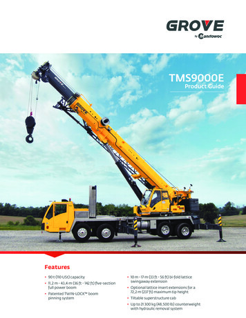
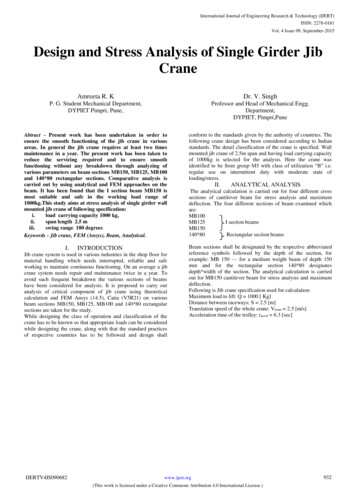
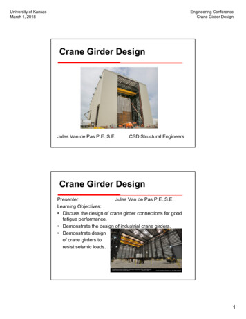
PRODUCT AND ENGINEERING MANUAL4.6 CRANESTOP RUNNING BRIDGE CRANE BRACKET DETAILSAH0010 – RUNWAY BEAM TO BRACKET CONNECTIONLAST REVISIONDATE:07/11/06BY: RJF CHK: KMCDETAIL NAME IF APPLICABLEAH0010.DWG4.6.4
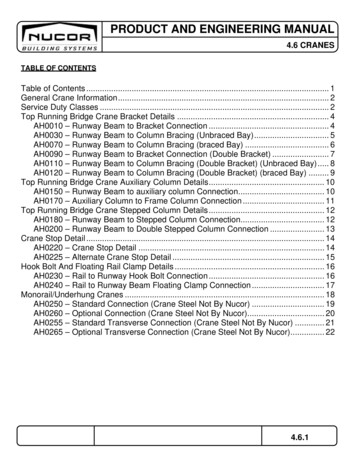
PRODUCT AND ENGINEERING MANUAL4.6 CRANESAH0030 – RUNWAY BEAM TO COLUMN BRACING (UNBRACED BAY)LAST REVISIONDATE: 03/03/05BY: KMC CHK:DETAIL NAME IF APPLICABLEEGBAH0030.DWG4.6.5
PRODUCT AND ENGINEERING MANUAL4.6 CRANESAH0070 – RUNWAY BEAM TO COLUMN BRACING (BRACED BAY)LAST REVISIONDATE: 03/03/05BY: KMC CHK:DETAIL NAME IF APPLICABLEEGBAH0070.DWG4.6.6
PRODUCT AND ENGINEERING MANUAL4.6 CRANESAH0090 – RUNWAY BEAM TO BRACKET CONNECTION (DOUBLE BRACKET)LAST REVISIONDATE:07/11/06BY: RJF CHK: KMCDETAIL NAME IF APPLICABLEAH0090.DWG4.6.7
PRODUCT AND ENGINEERING MANUAL4.6 CRANESAH0110 – RUNWAY BEAM TO COLUMN BRACING (DOUBLE BRACKET) (UNBRACED BAY)LAST REVISIONDATE: 03/03/05BY: KMC CHK:DETAIL NAME IF APPLICABLEEGBAH0110.DWG4.6.8
PRODUCT AND ENGINEERING MANUAL4.6 CRANESAH0120 – RUNWAY BEAM TO COLUMN BRACING (DOUBLE BRACKET) (BRACED BAY)LAST REVISIONDATE: 03/03/05BY: KMC CHK:DETAIL NAME IF APPLICABLEEGBAH0120.DWG4.6.9
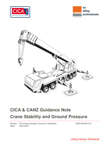
PRODUCT AND ENGINEERING MANUAL4.6 CRANESTOP RUNNING BRIDGE CRANE AUXILIARY COLUMN DETAILSAH0150 – RUNWAY BEAM TO AUXILIARY COLUMN CONNECTIONLAST REVISIONDATE:07/11/06BY: RJF CHK: KMCDETAIL NAME IF APPLICABLEAH0150.DWG4.6.10
PRODUCT AND ENGINEERING MANUAL4.6 CRANESAH0170 – AUXILIARY COLUMN TO FRAME COLUMN CONNECTIONLAST REVISIONDATE: 03/03/05BY: KMC CHK:DETAIL NAME IF APPLICABLEEGBAH0170.DWG4.6.11
PRODUCT AND ENGINEERING MANUAL4.6 CRANESTOP RUNNING BRIDGE CRANE STEPPED COLUMN DETAILSAH0180 – RUNWAY BEAM TO STEPPED COLUMN CONNECTIONLAST REVISIONDATE:07/11/06BY: RJF CHK: KMCDETAIL NAME IF APPLICABLEAH0180.DWG4.6.12
PRODUCT AND ENGINEERING MANUAL4.6 CRANESAH0200 – RUNWAY BEAM TO DOUBLE STEPPED COLUMN CONNECTIONLAST REVISIONDATE:07/11/06BY: RJF CHK: KMCDETAIL NAME IF APPLICABLEAH0200.DWG4.6.13
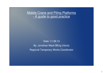
PRODUCT AND ENGINEERING MANUAL4.6 CRANESCRANE STOP DETAILAH0220 – CRANE STOP DETAILLAST REVISIONDATE: 08/11/04BY: KMC CHK:DETAIL NAME IF APPLICABLERJFAH0220.DWG4.6.14
PRODUCT AND ENGINEERING MANUAL4.6 CRANESAH0225 – ALTERNATE CRANE STOP DETAILLAST REVISIONDATE: 08/11/04BY: KMC CHK:DETAIL NAME IF APPLICABLERJFAH0225.DWG4.6.15
PRODUCT AND ENGINEERING MANUAL4.6 CRANESHOOK BOLT AND FLOATING RAIL CLAMP DETAILSAH0230 – RAIL TO RUNWAY HOOK BOLT CONNECTIONLAST REVISIONDATE: 03/03/05BY: KMC CHK:DETAIL NAME IF APPLICABLEEGBAH0230.DWG4.6.16
PRODUCT AND ENGINEERING MANUAL4.6 CRANESAH0240 – RAIL TO RUNWAY BEAM FLOATING CLAMP CONNECTIONLAST REVISIONDATE: 03/03/05BY: KMC CHK:DETAIL NAME IF APPLICABLEEGBAH0240.DWG4.6.17
PRODUCT AND ENGINEERING MANUAL4.6 CRANESMONORAIL/UNDERHUNG CRANES Underhung crane beams have rigid specifications with regard to tolerances. Manysuppliers of underhung systems require hardened flanges where crane wheelscome in contact with the crane beam. NBS standard approach to underhung andmonorail cranes is to design for the effects on the primary structural system only.Nucor will qualify back a maximum vertical frame deflection due to crane loadcombination; project engineer of record needs to review this information with cranesupplier. As a standard, all beams, rails, connections to main frames, etc. are byothers. NBS will design the frame of the building for the vertical and lateral loadsand the building longitudinal bracing for the longitudinal loads. There are capacity limits for the monorail and underhung cranes. For both cranetypes, we will not design to a CMAA service class above C. The monorail cranecapacity limit is 5 tons and the underhung capacity limit is 10 tons. It is important to specify clearly on the sketch of the building(s) included with theorder proposal the start and stop point, direction, orientation, and capacity of eachmonorail or underhung crane in the structure. Please also note that NBS standardconnection type designed for is the “truss” type. NBS will provide a web stiffenerplate to be welded in place directly over the centerline of the crane connection in therafter by an AWS certified welder in the field. We ship this stiffener plate loose forthe customer to place and weld because of the uncertainty of the exact end locationof the crane attachment. This allows the customer more flexibility during erection toallow for unknowns.LAST REVISIONDATE:02/09/01BY: CDM CHK: RJF4.6.18
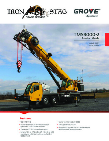
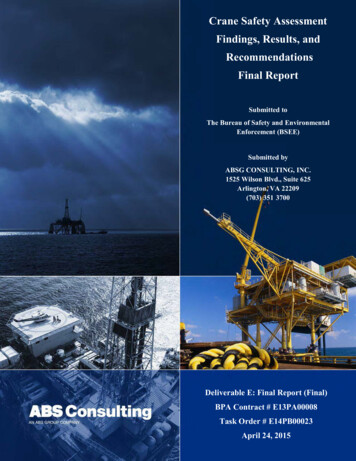
PRODUCT AND ENGINEERING MANUAL4.6 CRANESAH0250 – STANDARD CONNECTION (CRANE STEEL NOT BY NUCOR)LAST REVISIONDATE:08/11/04BY: KMC CHK: RJFDETAIL NAME IF APPLICABLEAH0250.DWG4.6.19
PRODUCT AND ENGINEERING MANUAL4.6 CRANESAH0260 – OPTIONAL CONNECTION (CRANE STEEL NOT BY NUCOR)LAST REVISIONDATE:08/11/04BY: KMC CHK: RJFDETAIL NAME IF APPLICABLEAH0260.DWG4.6.20
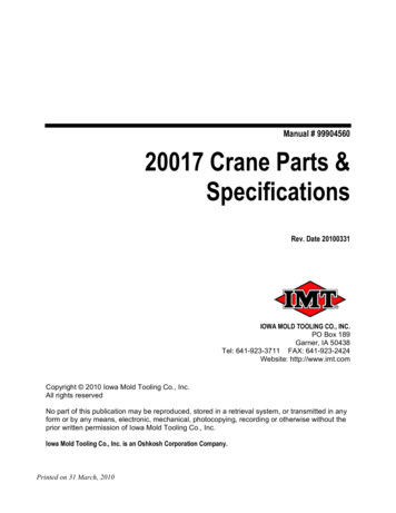
PRODUCT AND ENGINEERING MANUAL4.6 CRANESAH0255 – STANDARD TRANSVERSE CONNECTION (CRANE STEEL NOT BY NUCOR)LAST REVISIONDATE:08/11/04BY: KMC CHK: RJFDETAIL NAME IF APPLICABLEAH0255.DWG4.6.21
PRODUCT AND ENGINEERING MANUAL4.6 CRANESAH0265 – OPTIONAL TRANSVERSE CONNECTION (CRANE STEEL NOT BY NUCOR)LAST REVISIONDATE:08/11/04BY: KMC CHK: RJFDETAIL NAME IF APPLICABLEAH0265.DWG4.6.22
CMAA Specification #74, 1994 Revised. SERVICE DUTY CLASSES The CMAA (Ref. 74.2) has established six categories of crane service classification as a guide for determining the usage or serviceability requirements of a specific crane application. These criteria