Transcription
GUIDE TO MOBILE CRANES1This Guide provides information on mobile cranes and supports the General guide forcranes.This Guide also forms part of a series of guides and information sheets for cranes thatincludes information on: tower cranes inspecting and maintaining cranes bridge and gantry cranes vehicle loading cranes vessel-mounted cranes crane-lifted workboxes using other powered mobile plant as a crane, and quick-hitches for earth moving machinery.Note: vehicle loading cranes are technically mobile cranes for the purposes of designregistration but are not covered in this Guide.!What are mobile cranes?A mobile crane is a crane capable of travelling over a supporting surface without the needfor fixed runways and relying only on gravity for stability.They include three general types of mobile crane operating in Australia: hydraulic boom cranes lattice boom cranes including crawler cranes, and non-slewing (pick-and-carry) cranes.A slewing mobile crane is a mobile crane incorporating a boom or jib that can be slewed,but does not include earth moving equipment such as a front-end loader, backhoe, orexcavator configured for crane operation.A non-slewing mobile crane - also known as a pick up and carry crane - is a mobile craneincorporating a boom or jib that cannot be slewed and includes: an articulated mobile crane, or a locomotive crane.A vehicle tow truck is not considered to be a non-slewing mobile crane.A mobile crane can be set up in a range of locations and environmental conditions. Somemobile cranes, for example a non-slewing mobile crane can also carry a load while moving(known as mobiling).!High risk work licensingA person who operates a mobile crane (other than non-slewing mobile cranes with acapacity of less than 3 tonnes) must hold the relevant high risk work licence to operatethe crane. More information on high risk work licensing requirements is in the Generalguide for cranes.Safe Work Australia Contact InformationPhone 1300 551 832 Email info@swa.gov.au Web www.swa.gov.au978-1-76028-492-3 [Multi-Vol. Set]978-1-76028-470-1 [PDF]978-1-76028-471-8 [DOCX]
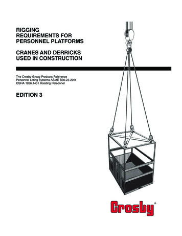
GUIDE TO MOBILE CRANES2!Crane stabilityFailure to maintain crane stability is one of the key factors associated with serious craneincidents. The main factors that affect crane stability include: operating the crane near its maximum rated capacity ground conditions and the means of supporting the crane’s outrigger pads, tyres ortracks the slope of the ground—both side slope and slope in direction of crane travel (thisparticularly applies to non-slewing mobile cranes), and wind conditions—this will vary depending on the size and shape of the suspended loadand crane boom.CounterweightsThe crane counterweight is critical in ensuring crane stability. A counterweight that is toolight for a load and boom configuration will cause the crane to overturn in the direction ofthe suspended load.A crane can also overturn backwards due to the effect of the counterweight in situationswhen: the counterweight is too heavy for the boom configuration the crane is travelling up a slope with the boom luffed up inadequate timbers are placed under the outrigger pads below the counterweightwhen the crane is positioned on soft ground, and outriggers are not extended or lowered into position.On smaller mobile cranes the counterweight is generally fixed and cannot be easilyremoved. Counterweights can be designed to be removed for road travel or when lighterloads are lifted. In this case it is important to attach the correct type and number ofcounterweights to the crane for the particular lift to be carried out.The crane manufacturer’s instructions specify how to secure the counterweights. Wherecounterweights are removable, each counterweight should be clearly identified with thecrane manufacturer’s name or trademark and the mass of the counterweight.Where the crane is fitted with a rated capacity limiter, the data input into the computermust be correct for the counterweight and boom configuration on the crane and relatedto that shown on the relevant load chart.Crane instrumentation including indicatorsSafety instrumentation and electronic load monitoring equipment fitted to mobile cranesinclude:Rated capacity limitersRated capacity limiters should be provided on mobile cranes manufactured since 2002with a rated capacity of more than 3 tonnes. The limiter should prevent exceeding therated capacity of the crane, within the tolerance of 100 to 110 per cent in order to preventlifting and radius increases.It is important that mobile cranes are operated within their rated design capacity.Working radius indicatorsA radius indicator displays the radius of the suspended load generally measured from thecentre of the slew ring. A radius indicator should be fitted on all mobile cranes that wereoriginally designed with this feature. The indicator should be displayed in metres and beaccurate to 10 per cent and -3 per cent of the actual radius.DECEMBER 2015
GUIDE TO MOBILE CRANES3Load indicatorsLoad indicators should be fitted to mobile cranes with a maximum rated capacity of morethan 3 tonnes. Load indicators measure and display the mass of the load being lifted. Thisindicator assists the crane operator to stay within the load chart and rated capacity of thecrane. The load indicator should be capable of displaying the mass of the suspended loadat all times.Load chartsLoad charts, also called rated capacity charts, identify what the crane is able to lift safely.The load chart should be available in the crane cabin for the crane operator to verify thecrane is not being overloaded.On some mobile cranes there may be more than one load chart for different boomand counterweight configurations. The load charts may be complex and include manyconditions that should be complied with to ensure the crane can safely lift a load.Stability function of load chartsWhen the load being lifted by the crane causes the crane to become unstable andoverturn this condition is called tipping. The maximum load that the crane can lift beforetipping occurs is calculated by applying a stability factor to work out when tipping mayoccur. The stability factor should be recorded on the crane load charts.The stability factor of mobile cranes allows for variables including: dynamic factors caused by the crane motion and the load e.g. for boom movement,application of brakes, swaying of the load, and wind effects on the load and boom.The stability factor typically used is: 75.0 per cent of tipping when the crane is operating on rubber or outriggers, and 66.6 per cent of tipping when the crane is operating in mobiling mode.It is however also possible for a crane to overturn with smaller loads when operating inwindy conditions, on sloping ground or if the crane is not operated smoothly.Wind conditionsStrong winds impose extra loads on a crane and may affect the crane’s stability. Toensure the stability of a mobile crane in windy conditions the following factors should beconsidered: The crane manufacturer’s instructions and load charts should state the maximum windspeed the crane can safely operate. Although a crane manufacturer may specify a maximum wind speed, a lowermaximum wind speed may need to be applied, for example where the load and boomhave large surface areas. Where the crane is lifting close to its rated capacity, wind speed is a critical factor asthe safety margin is lower and wind can more easily impact on the crane’s stability. Nearby thunderstorm activity may cause sudden very high speed wind conditionscalled microbursts which can lead to unexpected changes in the wind load on thecrane and make the load and crane unstable. Where the lift is a non-standard lift, with a suspended load or large surface area to becarried out in windy conditions, a competent person should provide written advice onsafe lifting conditions. For example, a lower maximum wind speed than that identifiedby the manufacturer may be applied. Check that wind gauges (anemometers) are operating. Wind gauges should bemounted at the boom tip where the highest wind loading will occur. Where windgauges are attached to the crane they should be mounted in accordance with themanufacturer’s instructions.DECEMBER 2015
GUIDE TO MOBILE CRANES4Ground factorsGround conditions can vary dramatically from one workplace to another and even withinone workplace. Failure to address poor ground conditions to ensure crane stability maycause the crane to overturn resulting in serious injury to the crane operator and otherpeople near the crane.Factors affecting ground support of cranes include: surface water, water mixed with soil e.g. mud and underground water like springs orstreams the type of ground e.g. clay, sand, rock or a mixture of these backfilled ground from a previous excavation or trench covered underground cavities or penetrations which still exist continued operation of the crane in one location, and the location of pressurised underground services e.g. a shallow fire hydrant mainwhich may burst if an outrigger is located directly above it.Decisions on the suitability of the ground conditions can only be made on the basis ofvisual inspection. Where it is difficult to work out if the ground conditions are suitable,documented information on the ground bearing pressure should be obtained from a geotechnical engineer. Rock usually provides the most stable supporting surface for a mobilecrane. Although rock may be present on the surface it may not extend far below thesurface. One way to establish how far rock may extend below the surface is to examinenearby excavations or trenches at the workplace. Rock that extends far below the surfaceprovides an indication of the ground’s integrity. Extra risks created when outriggers arepositioned close to an excavation must be managed.Whether the ground has a ‘crust’ on its surface should be checked. The surface of thistype of ground is usually firmer than the ground underneath. The firm surface may givethe impression that the ground is more stable than it actually is. If the ground is puncturedby an outrigger or the end of a crawler track, the softer ground will be exposed which maycause the crane to overturn.Where a mobile crane is continuously operated in one location the ground underneaththe outriggers will compact. The ground should be checked to ensure the crane has notcompacted it to the extent that the crane is more likely to overturn.Sloping groundCrane roll over can occur when a mobile crane travels along a side slope. Working on aslope has the effect of either increasing or decreasing the working radius of the crane,which may in turn affect the stability of the crane and cause the crane to overturn eitherforward, backwards or sideways.Most manufacturers of mobile cranes with mobiling capability specify the cranes shouldonly be operated on firm level ground. Working or travelling on sloping or uneven groundshould be avoided where possible. If working on slopes is unavoidable the crane should beused within the manufacturer’s specified capacity for operating on the relevant degree ofslope. Travel on a slope should be up or down the slope not across the slope.Where the centre of gravity of the mobile crane is high above the ground, a minimalground slope can be a major factor in causing the crane to overturn. This particularlyapplies when: the boom has a high luff angle the boom is telescoped out the centre of gravity of the suspended load is high, and there is articulation of an articulated crane.DECEMBER 2015
GUIDE TO MOBILE CRANES5A side slope of only 2 or 3 degrees can have a drastic effect on the stability of the crane.Soft ground, pneumatic tyres and suspension movement will also tend to increase the sideangle of the crane and increase the risk of overturning.Where fitted, the side slope inclinometer is to be used as a guide only as it is only accuratewhen the crane’s articulation is straight ahead with no load.Manufacturers and suppliers should provide clear documented information on themaximum side slope a crane can safely travel over while mobiling.Crane proximity to excavations and trenchesWhen cranes are set up close to excavations or trenches there may be an increased riskof the sides of the excavation or trench wall collapsing causing the crane to overturn. Thisrisk increases with softer ground and the presence of groundwater. The risk of collapse isgreater for vertical cuts in the excavation wall compared to walls that have been batteredback at an angle. The presence of ‘slippery back’ where there is a naturally occurring slipplane, for example a fracture in the ground, can also increase the risk of excavation ortrench collapse.The following principles should be applied when setting up mobile cranes nearexcavations: Where the ground is compact and not crumbling, the distance of any part of the craneoutrigger support dunnage from the excavation should be at least equal to the depthof the excavation (general 1:1 rule). Where the ground is loose or backfilled i.e. crumbling, the distance of any part of thecrane outrigger support dunnage from the excavation should be determined by acompetent person e.g. a geotechnical engineer.Outriggers and stabilisersStabilisers and outriggers have many configurations depending on the type of crane. Theyare used to minimise the risk of rollover when the centre of gravity of the combined loadand vehicle is outside the support base of the vehicle. Outriggers lift the vehicle’s wheelsoff the ground while stabilisers are mainly used on vehicle loading cranes and do not liftthe vehicles wheels off the ground.Using outriggers on mobile cranes helps to provide greater stability to the crane whenlifting loads. Irrespective of the ground conditions, timbers or other means of distributingthe load should be placed under the outriggers except where engineering indicates adirect outrigger pad applica
A crane can also overturn backwards due to the effect of the counterweight in situations when: the counterweight is too heavy for the boom configuration the crane is travelling up a slope with the boom luffed up inadequate timbers are placed under the outrigger pads below the counterweight when the crane is positioned on soft ground, and