Transcription
G500(H)/G600/G700 TXiSoftware v3.10What’s New
2020Garmin International, Inc., or its subsidiariesAll Rights ReservedExcept as expressly provided herein, no part of this manual may be reproduced, copied,transmitted, disseminated, downloaded or stored in any storage medium, for any purposewithout the express prior written consent of Garmin. Garmin hereby grants permission todownload a single copy of this manual and of any revision to this manual onto a hard drive orother electronic storage medium to be viewed and to print one copy of this manual or of anyrevision hereto, provided that such electronic or printed copy of this manual or revision mustcontain the complete text of this copyright notice and provided further that any unauthorizedcommercial distribution of this manual or any revision hereto is strictly prohibited.This document reflects the operation of system software v3.10. Some differences in operationmay be observed when comparing the information in this document to later software versions.SkyWatch and Stormscope are registered trademarks of L-3 Communications.SiriusXM Satellite Radio, Sirius, SXM and all related marks and logos are trademarks ofSiriusXM Radio Inc. All other marks and logos are property of their respective owners. All rightsreserved.Garmin , FliteCharts , and SafeTaxi are registered trademarks of Garmin International or itssubsidiaries. Connext , Garmin Pilot , G5 , GDU , GTN , and Smart Airspace aretrademarks of Garmin International or its subsidiaries. These trademarks may not be usedwithout the express permission of Garmin.The Bluetooth word mark and logos are registered trademarks owned by Bluetooth SIG, Inc.and any use of such marks by Garmin is under license.iPad and App Store are trademarks of Apple Inc. Windows is a trademark of Microsoft.SD is a registered trademark of SD-3C, LLC. All rights reserved.Iridium is a registered trademark of Iridium Communications, Inc. All rights reserved.The term Wi-Fi is a registered trademark of the Wi-Fi Alliance .Other trademarks and trade names are those of their respective owners.For information regarding the Aviation Limited Warranty, refer to Garmin’s website.For aviation product support, visit flyGarmin.com.SOFTWARE LICENSE AGREEMENTBY USING THE DEVICE, COMPONENT OR SYSTEM MANUFACTURED OR SOLD BY GARMIN("THE GARMIN PRODUCT"), YOU AGREE TO BE BOUND BY THE TERMS AND CONDITIONS OFTHE FOLLOWING SOFTWARE LICENSE AGREEMENT. PLEASE READ THIS AGREEMENTCAREFULLY. Garmin Ltd. and its subsidiaries ("Garmin") grants you a limited license to use thesoftware embedded in the Garmin Product (the "Software") in binary executable form in thenormal operation of the Garmin Product. Title, ownership rights, and intellectual property rightsin and to the Software remain with Garmin and/or its third-party providers. You acknowledgethat the Software is the property of Garmin and/or its third-party providers and is protectedunder the United States of America copyright laws and international copyright treaties. Youfurther acknowledge that the structure, organization, and code of the Software are valuabletrade secrets of Garmin and/or its third-party providers and that the Software in source codeform remains a valuable trade secret of Garmin and/or its third-party providers. You agree notto reproduce, decompile, disassemble, modify, reverse assemble, reverse engineer, or reduce tohuman readable form the Software or any part thereof or create any derivative works based onthe Software. You agree not to export or re-export the Software to any country in violation ofthe export control laws of the United States of America.
TXi Software v3.10SYSTEM . 1GDU 1060 Dual MFD and MFD/EIS Layouts .1New Interfaces .2MFD Engine Page on NON-EIS Units .2PFD . 3Dual-Knob PFD Control .3GFC 500 Localizer Autoswitch .3GPS Height Above Terrain .3CDI Source Menu .4Mach Number Display .4CDI and VDI indications on VFR Map (Rotorcraft) .4Variable Vno with Pressure Altitude .5Three-character V-speed Bugs .5GPS Roll Indicator .5MFD . 6Map/Weather Views .6Selected Altitude Range Arc (Any MFD Expansion) .6MFD Start Page Pre-Select .6EIS . 7Piper Meridian and Cirrus SR20/SR22 Support .711-Indicator Turboprop Layout .7Bar Gauge Digital Readout .7Digital Readout Color .7Rudder Trim Gauge .7Piston Engine Percent Power .8Turbine Engine Power Indicators .8Gauge Insets .8Bleed Valve and Inertial Separator Text Lamps .9Vacuum/Pressure Gauge .9Twin Engine Hour Meter .9Expanded Fuel Sender Support .10Advanced Fuel Quantity Gauge .10Selectable Fuel Quantity Gauges (Twin Cessna) .10ADVANCED FEATURES . 11Fuel Imbalance Monitor .11Auto Ignition .11Gauge-Driven Discrete Outputs Expansion .12190-01717-31 Rev. Ai
What’s New in v3.10NOTEThis document is intended for informational purposes only anddoes not provide operating instructions for the features described.For operating instructions, refer to the applicable revision ofG500(H)/G600/G700 TXi Pilot’s Guide.Reference ManualsDOCUMENTP/NG500(H)/G600/G700 TXi Pilot’s Guide, Rev. J190-01717-10Reference WebsitesWEBSITEADDRESSGarmin TXihttps://explore.garmin.com/en-US/txi/Garmin TXi Trainers(iOS and Windows PC) 1 Garmin trainers and simulators are provided free of charge.Available for DownloadElectronic Pilot’s GuideA version of this guide saved in Adobe Acrobat. Available for viewing on yourcomputer or portable device.Upgrade SupplementDetails document changes for software enhancements.Go to garmin.com/manualsii190-01717-31 Rev. A
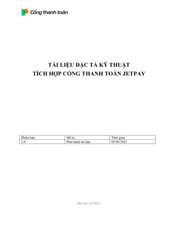
What’s New in v3.10SystemGDU 1060 DUAL MFD AND MFD/EIS LAYOUTSFEATURE LIMITATIONS/REQUIREMENTS GDU 1060 only Installer configurationWhen configured as an MFD, a Full/Split key toggles between dual MFD pagesand a full-screen MFD. An EIS strip may be added on either edge of the MFDdisplay.PG Section 1.2 - Display ConfigurationsPG Section 4.2 - MFD Display Size OptionsDual MFD/EISDual MFDFull MFD/EISFull-Screen MFD190-01717-31 Rev. A1
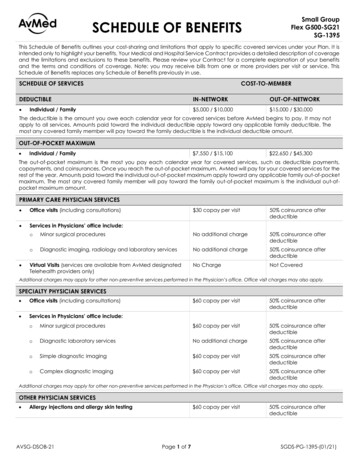
What’s New in v3.10MFD ENGINE PAGE ON NON-EIS UNITSFEATURE LIMITATIONS/REQUIREMENTS GDU 700P MFD, GDU 1060 MFD or PFD/MFD only Requires engine adapter (GEA 110 or GEA 71x) and installer configurationMFDs include an engine page when an engine adapter is present and configured.This provides an option for displaying engine information on displays other than afull-time EIS during phases of flight when engine monitoring is more important.For units with both MFD and EIS, display layouts are configured independently.PG Section 8.1 - EIS Display (Reciprocating Engine)PG Section 8.5 - EIS Display (Turbine)Engine Page, GDU 1060 PFD/MFDNEW INTERFACESThese components can now be interfaced with the TXi: GNC 355 GPS navigator with comm radio GI 275 multi-function display as standby attitudeindicator Avidyne DFC90 digital autopilot (requires featureenablement)GI 275GNC 3552190-01717-31 Rev. A
What’s New in v3.10PFDDUAL-KNOB PFD CONTROLFEATURE LIMITATIONS GDU 1060 PFD/MFD or PFD/MFD/EIS onlyFor aircraft with a cockpit configuration that makes it difficult to access the PFDknob, or simply for ease of use, both knobs may be used to control the PFD.Pushing and holding the inner knob toggles it between MFD and PFD controlfunctions. The MFD can still be controlled with the touchscreen when the adjacentknob is being used to control the PFD.PG Section 1.7 - Control KnobsGFC 500 LOCALIZER AUTOSWITCHFEATURE REQUIREMENTS GTN 650/750 with software v6.70 or later Installer configurationThe navigation source automatically switches from GPS to LOC when the autopilotcaptures the localizer.PG Section 2.10.6 - Automatic Source SelectionGPS HEIGHT ABOVE TERRAINFEATURE REQUIREMENTS GPS altitude available Terrain database availableAt altitudes lower than 2,500 ft AGL,calculated height above terrain is displayedadjacent to the altimeter strip.Toggle on AGL Field in PFD Setup to enablethe AGL display.PG Section 2.20 - AGL Display190-01717-31 Rev. A3
What’s New in v3.10MACH NUMBER DISPLAYFEATURE LIMITATIONS Aircraft configured for variableVNE/VMO and MMOAt speeds greater than Mach 0.4, the Machnumber is displayed above TAS.Toggle on Mach Field in PFD Setup to enablethe Mach display.MachPG Section 2.6 - Airspeed IndicatorCDI AND VDI INDICATIONS ON VFR MAP (ROTORCRAFT)FEATURE LIMITATIONS GDU 700L PFD VFR map Rotorcraft onlyPG Section 3 - Map Display, GDU 700LCDI SOURCE MENUFEATURE REQUIREMENTS More than two CDI sourcesTapping the CDI source key opens a source selectionmenu, allowing direct selection of the desired source.PG Section 2.10.3 - CDI Source Selection4190-01717-31 Rev. A
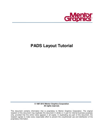
What’s New in v3.10VARIABLE VNO WITH PRESSUREALTITUDEFEATURE REQUIREMENTS Installer configurationFor aircraft with a VNO that varies withpressure altitude, the airspeed indicatorribbons are automatically adjusted.VNE/VMO/MMOPG Section 2.6.1 - Reference MarkingsVNOVFETHREE-CHARACTER V-SPEED BUGSVABOFEATURE REQUIREMENTS Installer configurationVSOBugs for V-speeds such as VABO and VWWOcan be displayed on the airspeed tape.Low SpeedAwareness BandPG Section 2.6.2 - Reference SpeedsGPS ROLL INDICATORA GPS roll indicator can provide roll steering guidance during GPS navigation.Toggle on GPS Roll Indicator in PFD Setup to enable the indicator.PG Section 2.22 - GPS Roll IndicatorRoll Indicator190-01717-31 Rev. A5
What’s New in v3.10MFDMAP/WEATHER VIEWSThe Map View key in the Map orWeather menus may be used toselect one of threeuser-configurable views.Saved map settings include mapoverlays, map detail level, and mapsetup configuration. All settingsconfigured in a weather product’smenu are saved.A custom name can be assigned toeach view.PG Section 4.4 - Map ViewsPG Section 5.3 - Weather MapViewsSELECTED ALTITUDE RANGE ARC(ANY MFD EXPANSION)Range ArcFEATURE REQUIREMENTS TXi system with at least one PFDAn arc representing the location at whichthe aircraft is expected to reach theselected altitude is displayed on the MFDmap when Selected ALT Range Arc istoggled on in Map Setup.PG Section 4.7.1 - Map SelectionsMFD START PAGE PRE-SELECTThe MFD can be set to start up on a desiredMFD page or hidden in order to display a full-screenPFD. Startup page selection is accessed through the System Setup menu.PG Section 4 - MFD Setup6190-01717-31 Rev. A
What’s New in v3.10EISPIPER MERIDIAN AND CIRRUS SR20/SR22 SUPPORTAlternate gauge layouts and a new percent power gauge allow TXi EIS to replaceprimary engine gauges for Piper Meridian and Cirrus SR20/SR22 aircraft.11-INDICATOR TURBOPROP LAYOUTFEATURE LIMITATIONS/REQUIREMENTS Turbine aircraft only Available on GDU 1060 EIS Requires installer configurationThe alternate 11-indicator layout is designed for aircraftthat require more gauges than are available in thestandard layout, such as the Piper Meridian. It providesseven secondary bar gauges, four of which are in aspecial narrow bar format.PG Section 8.5 - EIS DisplayBAR GAUGE DIGITAL READOUTFEATURE REQUIREMENTS Installer configurationBar gauges can be configured to display a digitalvalue to the right of the bar indicator.PG Section 8.3.1 - Gauge TypesDigital Readout11-Indicator TurbopropLayoutDIGITAL READOUT COLORWhen an indication is within a colored gauge range, the color of the digital readoutwill be the same as the range.RUDDER TRIM GAUGEFEATURE REQUIREMENTS Compatible trim sensors Installer configurationOriginal aircraft voltage-driven gauges may be replaced with a rudder trim gauge.190-01717-31 Rev. A7
What’s New in v3.10GaugesPISTON ENGINE PERCENT POWERFEATURE REQUIREMENTS Manifold pressure, RPM, fuelflow, and OAT sensors Installer configurationPercent power gauges are availableas primary gauges for bothnormally-aspirated andturbonormalized Cirrus aircraft,and as user-selectable gauges forother piston aircraft.PG Section 8.3.1 - Gauge TypesPG Section 8.3.5 - Selectable User FieldsTURBINE ENGINE POWER INDICATORSFEATURE LIMITATIONS/REQUIREMENTS Turbine aircraft only Torque and propeller RPM sensors Requires installer configurationPG Section 8.7.4 - SelectableUser FieldsShaft Horsepower (SHP) and Percent Power(%PWR) may be displayed inuser-selectable MFD engine page gaugesor EIS gauge insets.Refer to Gauge Insets for additional displayinformation.GAUGE INSETSFEATURE LIMITATIONS/REQUIREMENTS Turbine aircraft only Torque and propeller RPM sensors Requires installer configurationTorque and NP sunrise gauges can displayengine Shaft Horsepower (SHP) orPercent Power (%PWR) in an insetwindow.8PG Section 8.7.3 - OptionalGauge Features190-01717-31 Rev. A
What’s New in v3.10BLEED VALVE AND INERTIAL SEPARATOR TEXT LAMPSFEATURE LIMITATIONS/REQUIREMENTS Turbine aircraft only Requires installer configurationPG Section 8.7.3 - OptionalGauge FeaturesThe text lamps available for sunrise gaugesnow include Bleed Valve (BLEED) andInertial Separator (INSEP) lamps inaddition to Starter On, Ignition On, andReverse Thrust.VACUUM/PRESSURE GAUGEFEATURE REQUIREMENTS Vacuum/pressure sensor Installer configurationUp to two vacuum or pressure sources canbe monitored on a round or bar gauge.This gauge may be configured with acustom gauge title.PG Section 8.3.1 - Gauge Types(Reciprocating Engine)PG Section 8.3.1 - Gauge Types(Turbine)TWIN ENGINE HOUR METERFEATURE LIMITATIONS Twin engineaircraft onlyEngine hours are loggedseparately for each engineon twin engine aircraft.PG Section 8.14 - RecordKeeping190-01717-31 Rev. A9
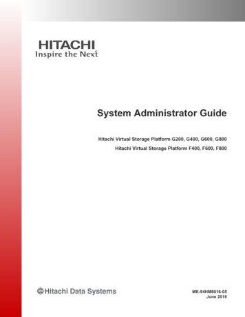
What’s New in v3.10EXPANDED FUEL SENDER SUPPORTFEATURE REQUIREMENTS Compatible engine adapter version (GEA 110 or GEA 71x) Installer configurationMost common resistive fuel senders are supported as well as CiES probes. Selectcapacitive fuel senders and fuel conditioners are also approved.ADVANCED FUEL QUANTITYGAUGEFEATURE REQUIREMENTS Fuel quantity sensors Installer configurationMerged Square DisplaysUp to six fuel quantities can be shownby merging two adjacent display slotswith three quantities per slot.Tank order and labels arecustomizable to match aircraftconfiguration.Single Bar DisplayPG Section 8.9 - Fuel GaugesSELECTABLE FUEL QUANTITYGAUGES (TWIN CESSNA)FEATURE REQUIREMENTS Fuel quantity sensorsSelected Selection switch interface Installer configurationFor aircraft with more than two fuel tanks,but with aircraft indicators which can onlydisplay two tank quantities at a time, the TXisystem simultaneously displays current fuelquantities for selected tanks and last knownfuel quantities for other tanks.NotSelected“Stale” fuel quantities are shown as graybars without digital readouts.PG Section 8.9 - Fuel Gauges10190-01717-31 Rev. A
What’s New in v3.10Advanced FeaturesFUEL IMBALANCE MONITORFEATURE LIMITATIONS/REQUIREMENTS Not compatible with selectable gauges Requires installer configurationAn advisory message and optional discrete output signals can be triggered by outof balance fuel loads. Fuel gauges for imbalanced tanks are outlined in yellow. Thediscrete signals may be used to control fuel pumps, external annunciators, or othersystems.Up to three pairs of fuel tanks and total imbalance minimum and maximum systemactivation thresholds are fully configurable. The discrete outputs function may beswitched on and off with an additional discrete input.PG Section 8.11 - Fuel Balance MonitoringFuel Imbalance IndicationAUTO IGNITIONFEATURE LIMITATIONS/REQUIREMENTS Turbine aircraft only Requires applicable sensors and installer configurationEngine ignition systems may be automatically switched on and off based on ITT,NG, NP, torque, condition lever position, and air/ground state. Activation anddeactivation conditions are configured separately.PG Section 8.12 - Automatic Ignition190-01717-31 Rev. A11
What’s New in v3.10GAUGE-DRIVEN DISCRETE OUTPUTS EXPANSIONFEATURE REQUIREMENTS Installer configurationThe TXi system can be configured to send a discrete signal to annunciators, relays,or other aircraft systems based on gauge values or ranges. This feature has beenexpanded to include these gauges: ITT Oil Pressure Battery Amps Torque Oil Temperature Battery Volts Propeller RPM Vacuum Pressure Fuel Quantity NG Alt/Gen Amps Engine Power Manifold Pressure Alt/Gen Volts Fuel Flow Bus Volts Flight Control TrimPositionPG Section 8.13 - Gauge Driven Discrete Outputs12190-01717-31 Rev. A
What’s New in v3.10SOFTWARE v3.10 UPGRADE SUMMARYFor systems using earlier software versions, upgrading to v3.10 adds: TAWS-A terrain Display of TCAS II traffic andresolution advisories Turbine EIS support EIS gauge dynamic markings Exceedance timers (turbine) Electrical gauges with up tosix parameters Airspeed tape configurablebugs GPS 175 and GNX 375support Emergency Descent Mode Additional FIS-B product support: Turbulence, Icing, G-AIRMET, Cloud Tops,Lightning, Center WX AdvisoriesContact your authorized Garmin dealer to request additional detailsabout these features and your new TXi installation or softwareupgrade: 17-31 Rev. A13
THE FOLLOWING SOFTWARE LICENSE AGREEMENT. PLEASE READ THIS AGREEMENT CAREFULLY. Garmin Ltd. and its subsidiaries ("Garmin") grants you a limited license to use the software embedded in the Garmin Product (the "Software") in binary executable form in the normal operation of the Garmin Product.