Transcription
RIGGINGREQUIREMENTS FORPERSONNEL PLATFORMSCRANES AND DERRICKSUSED IN CONSTRUCTIONThe Crosby Group Products ReferencePersonnel Lifting Systems ASME B30.23-2011OSHA 1926.1431 Hoisting PersonnelEDITION 3
Crosby Group Products ReferencePersonnel Platform – OSHA 1926.1431 and ASME B30.23Dear Crosby Customer,OSHA implemented revised rules for personnel lifting by use of a platformand a crane in the construction industry with the publishing of the final rule1926.1431(g)(1)(i)(A) and 1926.1501(g)(4)(iv)(B) Hoisting Personnel.ASME has developed ASME B30.23 under the procedures of ANSI. ASMEB30.23 establishes the design criteria, equipment characteristics andoperational procedures which are required when material handling equipment,as defined by the ASME B30 Standard, is used to lift personnel.Based on a review of these documents, Crosby is providing recommendationson the use of our products to meet both the OSHA and ASME requirements.Crosby does not recommend when personnel can be lifted or not. Ourrecommendations relate to the use of our products when the decision is made.The Market Leader: Yesterday, Today and Tomorrow“Crosby: There is No Equal”Copyright 2015 The Crosby Group LLCAll Rights Reserved
Crosby Group Products ReferencePersonnel Platform – OSHA 1926.1431 and ASME B30.23Table of ContentsLower Block Configuration. 2Overhaul Ball Configuration. 3Details of Master Link and Connections. 4Details of Connections at Platform. 5AppendixCrosby Latch Information. 6-8– Crosby S-4320 Hook Latch Kit. 6– Crosby Model PL-N/O Hook Latch Kit. 7– Crosby Model PL Hook Latch Kit. 8OSHA 1926.1431 – Hoisting Personnel. 9-15For Cranes and Derricks used in Demolition and Underground Construction, refer to OSHA 1926.1501.Copyright 2015 The Crosby Group LLCAll Rights Reserved1
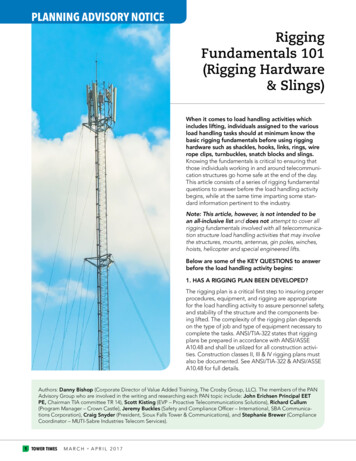
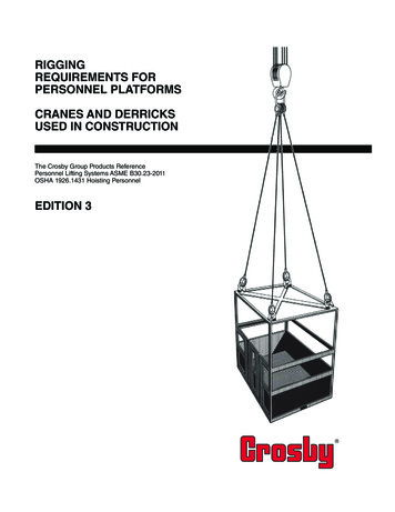
Crosby Group Products ReferencePersonnel Platform – OSHA 1926.1431 and ASME B30.23Lower Block ConfigurationSee page 3 for alternatives and details.Crosby or McKissick S-319 / S-319N hooks withpositive lock Model “PL” Latch with Locking Bolt/NutAssembly (or S-4320 Latch when properly appliedwith cotter pin) per OSHA 1926.1431(g)(1)(i)(A) &(B) and ASME B30.23-1.2.2(e).Crosby A-342 AlloyMaster Links per OSHA1926.1431(g)(2) and ASMEB30.23-1.1.1(10)(d) See page3 for details.Flemish eye with Crosby G-414 extra heavythimble formed with National S-505 sleeve perOSHA 1926.1431(g)(4) and ASMEB30.23-1.1.1(10)(a). See page 4 for details.Bridles and associated rigging can only be usedfor suspending the personnel platform per OSHA1926.1431(g)(5) and ASME B30.23-1.1.1(10).Flemish eye with Crosby G-414 extra heavythimble formed with National S-505 sleeve. Seepage 4 for alternatives and details.Crosby G-2140 bolttype shackles per ASMEB30.23-1.1.1(10)(i) andOSHA 1926.1431(g)(1)(ii)(A). See page 5 fordetails.The Personnel Platform per OSHA1926.1431(e) and ASME B30.23-1.2.2Copyright 2015 The Crosby Group LLCAll Rights Reserved
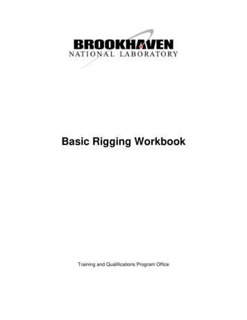
Crosby Group Products ReferencePersonnel Platform – OSHA 1926.1431 and ASME B30.23Overhaul Ball Configuration – Alternative to Lower BlockPL LatchPL-N/O LatchS-4320 Latch with Cotter PinOverhaul BallCrosby S-1316A or S-320A / S-320AN hooks with S-4320Latch (when properly applied with cotter pin) or Positive-LockModel “PL” Latch with Locking Bolt/Nut Assembly per OSHA1926.1431(g)(1)(i)(A) & (B) and ASME B30.23-1.2.2(e).McKissick 380Series Block with319N hook and PLLatchCopyright 2015 The Crosby Group LLCAll Rights ReservedUB-500 OverhaulBall with S-1316Ahook3
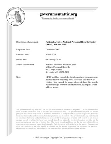
Crosby Group Products ReferencePersonnel Platform – OSHA 1926.1431 and ASME B30.23Details of Master Link and ConnectionsCrosby A-342 Alloy Forged MasterLinks per OSHA 1926.1431(g)(2) andASME B30.23-1.1.1(10)(d)Flemish eye with Crosby G-414 extraheavy thimble per OSHA 1926.1431(g)(4)and ASME B30.23-1.1.1(10)(a)Flemish eye formed with National S-505 sleeve per ASMEB30.23-1.1.1(10)(a)Wire Rope SlingOther notes:Bridles and associated rigging can only be used for suspending the personnel platform per OSHA 1926.1431(g)(5)and ASME B30.23-1.1.1(10).Each leg of the system shall be permanently marked with the rated load of the leg per ASME B30.23-1.1.1(10)(h).The alloy master link shall be marked with the suspension system’s rated load and indentification as a personnel liftingsystem component per ASME B30.23-1.1.1(10)(h).4Copyright 2015 The Crosby Group LLCAll Rights Reserved
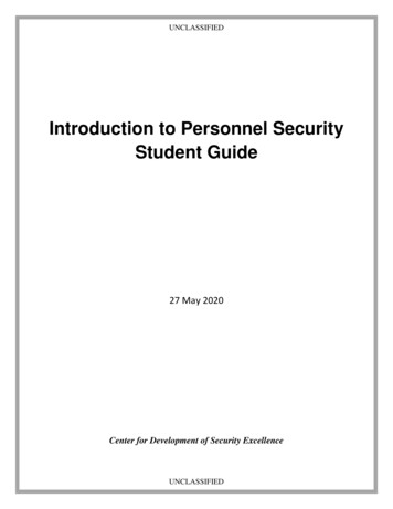
Crosby Group Products ReferencePersonnel Platform – OSHA 1926.1431 and ASME B30.23Details of Connection to PlatformWire Rope SlingFlemish eye formed with National S-505sleeve per ASME B30.23-1.1.1(10)(a)Flemish eye with Crosby G-414 extraheavy thimble per OSHA 1926.1431(g)(4)and ASME B30.23-1.1.1(10)(a)Crosby G-2140 bolt type shackles perASME B30.23-1.1.1(10)(i) and OSHA1926.1431(g)(1)(ii)(A)Other notes:Wire Rope Bridle used only for suspending the personnel platform perOSHA 1926.1431(g)(5) and ASME B30.23-1.1.1(10).Rope suspension systems with poured socket end connections (inplace of shackles) shall be designed in accordance with manufacturer’sinstructions per ASME B30.23-1.1.1(10)(b). There is no prohibition to useswage sockets.Copyright 2015 The Crosby Group LLCAll Rights Reserved5
Crosby Group Products ReferencePersonnel Platform – OSHA 1926.1431 and ASME B30.23S-4320 HOOK LATCH KITWARNING(For Crosby 319N, 320N, and 322N,S-1327, and A-1339 Hooks) Loads may disengage from hook if properprocedures are not followed. A falling load may cause serious injury or death. Hook must always support the load. The loadmust never be supported by the latch. See OSHA Rule 1926.1431(g)(1)(i)(A) and1926.1501(g)(4)(iv)(B) for personnel hoisting bycrane or Derricks. A Crosby S-319N, S-320N,S-322N, S-1327, and A-1339 Hook with an S-4320latch attached (When secured with cotter pin)may be used for lifting personnel. An S-4320 Latch is only to be used with a CrosbyS-319N, S-320N, S-322N, S-1327, and A-1339 Hook. DO NOT use this latch in applications requiringnon-sparking. Read and understand these instructions beforeusing hook and latch.WARNING ANDAPPLICATIONINSTRUCTIONS Always inspect hook and latch before using.Never use a latch that is distorted or bent.Always make sure spring will force the latch against the tipof the hook.Always make sure hook supports the load. The latch mustnever support the load. (See Figure 1 & 2.)When placing two (2) sling legs in hook, make sure theangle between the legs is less than 90 and if the hook orload is tilted, nothing bears against the bottom of this latch.(See Figure 3 & 4.)Latches are intended to retain loose sling or devices underslack conditions.Latches are not intended to be an anti-fouling device.When using latch for personnel lifting, select proper cotterpin (See Figure 5). See Step 7 below for proper installationinstructions. Never reuse a bent cotter pin. Never use a cotter pin with a smaller diameter ordifferent length than recommended in Figure 5. Never use a nail, a welding rod, wire, etc., in place ofrecommended cotter pin. Always ensure cotter pin is bent so as not to interferewith sling operation. Periodically inspect cotter pin for corrosion andgeneral adequacy.Figure 5RIGHTWRONGRIGHTWRONGFigure 1Figure 2Figure 3Figure 4Hook IdentificationCodeDFGHIJKLNRecommendedCotter Pin † The current SS-4055 latch kit and the PL latch will not fit new 319N, 320N, or322N hooks. They will continue to be offered in both styles to service existinghooks. Important – The new S4320 latch kit will not fit the old 319, 320, or322 hooks.IMPORTANT – Instructions for Assembling S-4320 Latch on Crosby 320N HooksStep 11. Place hook atapproximately a 45degree angle with thecam up.6Step 2Step 3Steps 4, 5, & 62. Position coils of springover cam with legs ofspring pointing towardpoint of hook and loop ofspring positioned downand lying against thehook.3. Position latch to side ofhook points. Slide latchonto spring legs betweenlockplate and latch bodyuntil latch is partially overhook cam. Then depresslatch and spring untillatch clears point of hook.4. Line up holes in latchwith hook cam.5. Insert bolt throughlatch, spring, and cam.6. Tighten self-locking nuton one end of bolt.Step 7 – ForPersonnel Lifting7. With latch in closedposition and riggingresting in bowl of hook,insert cotter pin throughhook tip and secure bybending prongs.Copyright 2015 The Crosby Group LLCAll Rights Reserved
Crosby Group Products ReferencePersonnel Platform – OSHA 1926.1431 and ASME B30.23CROSBY MODEL PL-N/OHOOK LATCH KITWARNINGWARNINGS AND APPLICATIONINSTRUCTIONS Loads may disengage from hook if proper procedures arenot followed. A falling load may cause serious injury or death. See OSHA Rule 1926.1431(g)(1)(i)(A) and 1926.1501(g)(4)(iv)(B)for Personnel Hoisting by Crane or Derricks. A Crosby orMcKissick Hook with a Positive Locked PL-N/O or S-4320Latch may be used to Lift Personnel. Hook must always support the load. The load must neverbe supported by the latch. DO NOT use this latch in applications requiring nonsparking. Read and understand these instructions before using hookand latch.RIGHTWRONGFigure 1Figure 2Model PL-N/OImportant Safety Information Read and Follow Always inspect hook and latch before using.Never use a latch that is distorted or bent.Always make sure spring will force the latch against thetip of the hook.Always make sure hook supports the load. The latchmust never support the load. (See Figure 1 & 2.)When placing two (2) sling legs in hook, make sure theangle between the legs is less than 90 and if the hookor load is tilted, nothing bears against the bottom of thislatch. (See Figure 3 & 4.)Latches are intended to retain loose sling or devicesunder slack conditions.Latches are not intended to be an anti-fouling device.RIGHTWRONGFigure 3Figure 4IMPORTANT - Instructions for Assembling Model PL-N/O Latchon Crosby or McKissick HooksStep 1Step 2Step 3 4, 5, & 61. Place hook in uprightposition. Position coilsof spring over cam withlegs of spring pointingtoward tip of hook,and loop of springpositioned down andlying against the hook.2. Slip the latch overthe spring until the twospring legs are positioned into the grooveslocated on the insideof the latch housing(legs of spring should fitbetween the gate andthe housing).3. Slide latch housingup the spring legs untillatch clears hook tip.4. Resting latch oninterlocking hook tip,line up holes in latchwith hook cam.5. Insert bolt throughlatch spring & cam.6. Tighten self-lockingnut on one end of bolt.Copyright 2015 The Crosby Group LLCAll Rights ReservedStep 7,8 - ForPersonnel Lifting7. Rigging shouldbe resting in bowl ofhook, with latch inclosed position andgate locked.8. Insert toggle lockpin through hole anddepress spring untiltoggle clears hole onother side of latch.Step 9 - ForPersonnel Lifting9. Rotate toggle 90degrees to securepin (ensure toggle isin closed position asshown).rev. 37
Crosby Group Products ReferencePersonnel Platform – OSHA 1926.1431 and ASME B30.23CROSBY MODEL PL HOOKLATCH KITWARNINGS AND APPLICATIONINSTRUCTIONSWARNING Loads may disengage from hook if proper procedures arenot followed. A falling load may cause serious injury or death. See OSHA Rule 1926.1431(g)(1)(i)(A) and 1926.1501(g)(4)(iv)(B)for Personnel Hoisting by Cranes or Derricks. A Crosby orMcKissick Hook with a positive Locked PL or S-4320 Latchmay be used to Lift Personnel. Hook must always support the load. The load must neverbe supported by the latch. DO NOT use this latch in applications requiring non-sparking. Read and understand these instructions before using hookand latch.RightWrongModel PLImportant Safety Information Read & Follow(Pat. USA & Canada) Always inspect hook and latch before using.Never use a latch that is distorted or bent.Always make sure spring will force the latch against thetip of the hook.Always make sure hook supports the load. The latchmust never support the load. (See Figure 1 & 2.)When placing two (2) sling legs in hook, make sure theangle between the legs is less than 90 and if the hookor load is tilted, nothing bears against the bottom of thislatch. (See Figure 3 & 4.)Latches are intended to retain loose sling or devicesunder slack conditions.Latches are not intended to be an anti-fouling device.Figure 1Figure 2RightWrongFigure 3Figure 4IMPORTANT - Instructions for Assembling Model PL Latch on Crosby or McKissick HooksStep 11. Place hook atapproximately a 45degree angle with thecam up.rev. 38Step 22. Position coils of springover cam with legs ofspring pointing towardpoint of hook and loop ofspring positioned downand lying against thehook.Step 33. Position latch to side ofhook points. Slide latchonto spring legs betweenlockplate and latch bodyuntil latch is partially overhook
09.08.2010 · sleeve per ASME B30.23-1.1.1(10)(a) Other notes: Wire Rope Bridle used only for suspending the personnel platform per OSHA 1926.1431(g)(5) and ASME B30.23-1.1.1(10). Rope suspension systems with poured socket end connections (in place of shackles) shall be designed in accordance with manufacturer’s instructions per ASME B30.23-1.1.1(10)(b .