Transcription
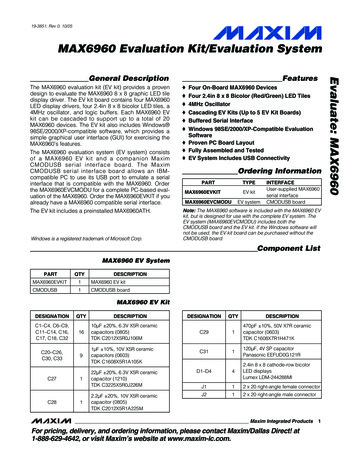
19-3851; Rev 0; 10/05MAX6960 Evaluation Kit/Evaluation SystemThe MAX6960 evaluation kit (EV kit) provides a provendesign to evaluate the MAX6960 8 x 8 graphic LED tiledisplay driver. The EV kit board contains four MAX6960LED display drivers, four 2.4in 8 x 8 bicolor LED tiles, a4MHz oscillator, and logic buffers. Each MAX6960 EVkit can be cascaded to support up to a total of 20MAX6960 devices. The EV kit also includes Windows 98SE/2000/XP-compatible software, which provides asimple graphical user interface (GUI) for exercising theMAX6960’s features.The MAX6960 evaluation system (EV system) consistsof a MAX6960 EV kit and a companion MaximCMODUSB serial interface board. The MaximCMODUSB serial interface board allows an IBMcompatible PC to use its USB port to emulate a serialinterface that is compatible with the MAX6960. Orderthe MAX6960EVCMODU for a complete PC-based evaluation of the MAX6960. Order the MAX6960EVKIT if youalready have a MAX6960 compatible serial interface.The EV kit includes a preinstalled MAX6960ATH.Windows is a registered trademark of Microsoft Corp.Features Four On-Board MAX6960 DevicesFour 2.4in 8 x 8 Bicolor (Red/Green) LED Tiles4MHz OscillatorCascading EV Kits (Up to 5 EV Kit Boards)Buffered Serial InterfaceWindows 98SE/2000/XP-Compatible EvaluationSoftware Proven PC Board Layout Fully Assembled and Tested EV System Includes USB ConnectivityOrdering InformationPARTTYPEEV kitMAX6960EVKITEV systemMAX6960EVCMODUINTERFACEUser-supplied MAX6960serial interfaceCMODUSB boardNote: The MAX6960 software is included with the MAX6960 EVkit, but is designed for use with the complete EV system. TheEV system (MAX6960EVCMODU) includes both theCMODUSB board and the EV kit. If the Windows software willnot be used, the EV kit board can be purchased without theCMODUSB board.Component ListMAX6960 EV SystemPARTQTYMAX6960EVKIT1MAX6960 EV kitDESCRIPTIONCMODUSB1CMODUSB boardMAX6960 EV KitDESIGNATIONQTYC1–C4, C6–C9,C11–C14, C16,C17, C18, C321610µF 20%, 6.3V X5R ceramiccapacitors (0805)TDK C2012X5R0J106MC20–C26,C30, C3391µF 10%, 10V X5R ceramiccapacitors (0603)TDK CRIPTIONC291470pF 10%, 50V X7R ceramiccapacitor (0603)TDK C1608X7R1H471KC311120µF, 4V SP capacitorPanasonic EEFUD0G121R22µF 20%, 6.3V X5R ceramiccapacitor (1210)TDK C3225X5R0J226MD1–D442.4in 8 x 8 cathode-row bicolorLED displaysLumex LDM-244288MIJ112 x 20 right-angle female connector2.2µF 20%, 10V X5R ceramiccapacitor (0805)TDK C2012X5R1A225MJ212 x 20 right-angle male connectorMaxim Integrated ProductsFor pricing, delivery, and ordering information, please contact Maxim/Dallas Direct! at1-888-629-4642, or visit Maxim’s website at www.maxim-ic.com.1Evaluate: MAX6960General Description
MAX6960 Evaluation Kit/Evaluation SystemEvaluate: MAX6960Component List (continued)MAX6960 EV KitDESIGNATIONQTYJU1–JU5,JU7–JU11, JU13113-pin headersMAX6960.EXERuns application program.HELPFILE.HTMOpens the MAX6960 EV kit Helpfile.2-pin headersJU120PC board trace power jumper,not installed (open)L111.5µH inductor (ISAT 4A)Sumida CDRH6D28 4762T064TROUBLESHOOTING Opens the USB driver installation helpUSB.PDFfile.FTD2XX.INFUSB device driver file.UNINST.INIUninstalls the EV kit software.*.CM2R1, R2, R3, R6,R751kΩ 5% resistors (0603)R4110Ω 5% resistor (0603)R5184.5kΩ 1% resistor (0603)RP1–RP8020kΩ potentiometers, top adjust,not installedU1–U44MAX6960ATH (44-pin TQFN, 7mmx 7mm x 0.8mm)6Three-state logic buffers(5-pin SOT23)Fairchild SemiconductorNC7SZ126M5XTopmark7Z26U1014MHz silicon oscillator(3-pin SC70)Maxim MAX7375AXR405-TTopmarkAORU1118-channel multiplexer(16-pin TSSOP)Maxim MAX4617EUE3A step-down switching regulator(16-pin QSOP)Maxim MAX1831EEEU121—16Shunts—1MAX6960EVKIT blank PC board—1MAX6960EVKIT SW CD-ROMPHONEMAX6960 8-bit write script files.Quick StartComponent SuppliersWEBSITELumex, www.panasonic.comSumida mponent.tdk.comNote: Indicate you are using the MAX6960 when contactingthese component suppliers.2DESCRIPTIONInstalls the EV kit files on 6, JU14–JU17U5–U9, U13MAX6960 EV Kit FilesThis quick start includes directions for using only oneMAX6960 EV kit board. See the Cascading MAX6960EV Kit Boards section when using more than oneMAX6960 EV kit.Recommended Equipment The MAX6960 EV systemMAX6960EVKITCMODUSB serial interface board(USB cable included) Power supply: 5V at 2.5A per MAX6960 EV kit A user-supplied Windows 98SE/2000/XP PC with USBProceedureDo not turn on the power until all connections aremade.1) Verify jumper J1 on the CMODUSB board is connected to pins 2-3. This process sets the logic supply to 3.3V.2) Verify the following MAX6960 EV kit jumpers are inthe default positions:JU1: (2-3)JU2: (2-3)JU3: (1-2)JU4: (2-3)JU5: (2-3)JU10: (2-3)JU11: (2-3)JU12: (Open)JU13: (1-2)JU14: (1 only)JU6: (1-2)JU7: (2-3)JU8: (2-3)JU9: (1-2)JU15: (1-2)JU16: (1-2)JU15: (1 only)
MAX6960 Evaluation Kit/Evaluation System6) Connect the included USB cable from the PC to theCMODUSB board. A Building Driver Database window pops up in addition to a New Hardware Foundmessage. If you do not see any window that is similarto the one described above after 30 seconds, removethe USB cable from the CMODUSB board and reconnect it again. Administrator privileges are required toinstall the USB device driver on Windows 2000 andXP. Refer to the document Troubleshooting USB.PDFincluded with the software for more information.7) Follow the directions of the Add New HardwareWizard to install the USB device driver. Choose theSearch for the best driver for your device option.Specify the location of the device driver to beC:\Program Files\MAX6960 using the Browse button.8) Start the MAX6960 EV kit software by opening itsicon in the Windows Start menu Programs MaximMAX6960 Evaluation Kit. If the 16-color demo modeis visible, then quick start is complete.Loading Scripts (Optional)1) Press the Load 8-bit Write Script button on the 8and 16-bit addr modes tab.2) Load the script file 1bit step1 box.cm2 located inthe C:\Program Files\MAX6960 directory.3) Press the Run 8-bit Write Script (16bytes) button inthe 8-bit Write Script window.4) Press the Load Next Script button and load thescript file 1bit step2 box.cm2 located in theC:\Program Files\MAX6960 directory.5) Press the Run 8-bit Write Script (16bytes) button inthe 8-bit Write Script window.Detailed Description of SoftwareThe evaluation software’s main window shown in Figure1 displays tabs for 8-bit, 16-bit, and 24-bit addressingmodes as well as individual tabs for each register in theMAX6960’s register address map (0x00 through 0x0F).Table 1 describes the controls that are always presenton the evaluation software’s main window.The 8 and 16-bit addr modes tab, shown in Figure 1,allows the user to execute 8-bit and 16-bit address modeoperations. The 8-bit address mode is the quickestmethod of updating a plane of display memory in theMAX6960 and is write only. During the 8-bit addressTable 1. MAX6960 EV Kit Software Main Window Control DescriptionsCONTROLDESCRIPTIONAllows the user to select the active register tab.Shows the CMODUSB debugging tools.Gives access to the Helpfile and the About box.Automatically sets the global driver devices and the global driver rows registers of the masterMAX6960 to the correct values when cascading boards.Resets all the registers to the software reset settings.For example: 2-bits/pixel bicolor mode Register 0x0D 0xC1 4 driver devices (N-1) Register 0x0E 0x03 2 driver rows (N-1) Register 0x0F 0x01Resets all the registers to the IC power-on reset (POR) settings shown in the MAX6960 datasheet.Displays the CMODUSB connection status. CMOD means that it supports both theCMODUSB or CMOD232 boards.Exits the program.3Evaluate: MAX69603) Connect the MAX6960 EV kit’s 40-pin female connector (J1) to the CMODUSB board’s 40-pin maleconnector (P4).4) Install the MAX6960 evaluation software on your computer by running the INSTALL.EXE program on theinstallation CD-ROM. It is highly recommended to usethe default installation path. If you desire to modifythe default path, do not use a depth of more than twosubdirectories. The program files are copied andicons are created for them in the Windows Startmenu Programs Maxim MAX6960 Evaluation Kit.5) Connect the 5V power supply between the MAX6960EV kit’s 5V and GND pads.Turn on the 5V power supply. Do not connect the USB cable before this step.
Evaluate: MAX6960MAX6960 Evaluation Kit/Evaluation SystemFigure 1. MAX6960 Evaluation Software Main Windowmode, data is written to the display memory using indirection through the global display indirect address register. This display indirect address is autoincrementedafter each 8-bit write to allow continuous image datadumps into the plane of display memory in the MAX6960.The 16-bit address mode is capable of reading or writing command/data bytes to the MAX6960’s registers. A16-bit write can be global (updates all MAX6960s withthe same data) or local (only one MAX6960). A 16-bitread always uses indirection through the global driverindirect address register to select only one MAX6960.Refer to the Register Addressing Modes section of theMAX6960 data sheet for additional information.4The 24-bit addr modes (1 bit/pixel) tab shown inFigure 2, and the 24-bit addr modes (2 bit/pixel) tabshown in Figure 3, allow the user to execute 24-bitaddress mode operations. A 24-bit operation is alwaysa direct read or write of address/data to the MAX6960’sdisplay memory because the memory address isincluded in the 24-bit operation. Refer to the RegisterAddressing Modes section of the MAX6960 data sheetfor additional information.
MAX6960 Evaluation Kit/Evaluation SystemEvaluate: MAX6960Figure 2. 24-Bit Addressing Modes (1 Bit/Pixel) Tab5
Evaluate: MAX6960MAX6960 Evaluation Kit/Evaluation SystemFigure 3. 24-Bit Addressing Modes (2 Bits/Pixel) Tab6
MAX6960 Evaluation Kit/Evaluation SystemMAX6960 EV SystemThe MAX6960 EV system is a PC-controlled LED display system consisting of a MAX6960 EV kit and theMaxim CMODUSB serial interface board.Table 4. Digit 1 Current Setting(RISET1—U1)JUMPERSHUNTPOSITION1-2CMODUSB Serial Interface BoardThe CMODUSB serial interface board uses a proprietary design to provide SPI - and I 2 C-compatibleinterfaces to demonstrate various Maxim devices.Maxim reserves the right to change the implementationof this module at any time with no advance notice.CMODUSB Power SupplyThe CMODUSB board uses a MAX1658 linear regulator.Jumper J1 selects between a 5V or 3.3V system supplyvoltage. Do not plug a wall cube into the P1 power jackbecause power is provided from the USB port.JU22-3*OpenTable 5. Address Data Input ION1-22-3*SYSTEM SUPPLY VOLTAGE(DVDD)5V3.3V*Make sure the J1 jumper on the CMODUSB board is in the 2-3position when using the MAX6960 EV kit.MAX6960 EV KitThe MAX6960 EV kit contains four MAX6960 devices(U1–U4), a 16 x 16 dot-matrix display (D1–D4), a stepdown voltage regulator (U12), a 4MHz oscillator (U10),and logic buffers (U5–U9, U13). The MAX6960 EV kitrequires a 5V supply (rated for 2.5A per EV kit) and upto five MAX6960 EV kits can be cascaded allowing theuser to evaluate up to 20 MAX6960 devices.Tables 3 through 19 explain the functionality of eachjumper when using only one MAX6960 EV kit.Table 3. Digit 0 Current penAll U1 digit 1 segment currentsadjustable from 20mA to 40mA.All U1 digit 1 segment currents setto 40mA.All U1 digit 1 segment currents setto 20mA.*Default configuration.Table 2. CMODUSB Jumper J1 (SystemSupply Voltage)JUMPERDESCRIPTION2-3DESCRIPTIONADDIN of U1 is connected to 3.3V to indicate the firstMAX6960 device.See the Cascading MAX6960 EVKit Boards section for details.*Default configuration.Table 6. Digit 0 Current penDESCRIPTIONAll U2 digit 0 segment currentsadjustable from 20mA to 40mA.All U2 digit 0 segment currents setto 40mA.All U2 digit 0 segment currents setto 20mA.*Default configuration.DESCRIPTIONAll U1 digit 0 segment currentsadjustable from 20mA to 40mA.All U1 digit 0 segment currents setto 40mA.All U1 digit 0 segment currents setto 20mA.SPI is a trademark of Motorola, Inc.*Default configuration.7Evaluate: MAX6960Detailed Description of Hardware
Evaluate: MAX6960MAX6960 Evaluation Kit/Evaluation SystemTable 7. Digit 1 Current penDESCRIPTIONAll U2 digit 1 segment currentsadjustable from 20mA to 40mA.All U2 digit 1 segment currents setto 40mA.All U2 digit 1 segment currents setto 20mA.Table 10. Digit 1 Current penDESCRIPTIONAll U3 digit 1 segment currentsadjustable from 20mA to 40mA.All U3 digit 1 segment currents setto 40mA.All U3 digit 1 segment currents setto 20mA.*Default configuration.*Default configuration.Table 8. U2 New Row Selection(NEWROWBUS—U2)Table 11. Address Data ESCRIPTIONADDOUTU2 is connected toNEWROWBUS to start the secondrow of 8 x 8 LED displays.See the Cascading MAX6960 EVKit Boards section for DIN of U3 is connected toNEWROWBUS to start the secondrow of 8 x 8 LED displays.See the Cascading MAX6960 EVKit Boards section for details.*Default configuration.*Default configuration.Table 9. Digit 0 Current Setting(RISET0—U3)Table 12. Digit 0 Current pen*Default configuration.8DESCRIPTIONAll U3 digit 0 segment currentsadjustable from 20mA to 40mA.All U3 digit 0 segment currents setto 40mA.All U3 digit 0 segment currents setto All U4 digit 0 segment currentsadjustable from 20mA to 40mA.All U4 digit 0 segment currents setto 40mA.All U4 digit 0 segment currents setto 20mA.*Default configuration.
MAX6960 Evaluation Kit/Evaluation SystemTable 17. Put U8 in a Known IPTIONAll U4 digit 1 segment currentsadjustable from 20mA to 40mA.All U4 digit 1 segment currents setto 40mA.All U4 digit 1 segment currents setto 20mA.*Default configuration.Table 14. 5V Power-Line Pass OpenDESCRIPTIONPut U8 in a known state whenusing only one MAX6960 EV kit.See the Cascading MAX6960 EVKit Boards section for details.*Default configuration.Table 18. LED Open Circuit Test(U1COL1)JUMPERDESCRIPTIONSee the Cascading MAX6960 EVKit Boards section for details.User applies 5V between the 5V and GND pads for the firstMAX6960 EV PTIONNormal operation.Creates an open circuit on theU1COL1 line of D1 and is used foran LED open circuit test.*Default configuration.*Default configuration.Table 15. Oscillator Buffer Output (OSC)JUMPERSHUNTPOSITION1-2*JU132-3DESCRIPTIONThe MAX7375 silicon oscillator isrouted to U1, U2, U3, and U4.See the Cascading MAX6960 EVKit Boards section for details.Table 19. ADDCLK Pass SCRIPTIONSee the Cascading MAX6960 EVKit Boards section for details.Do not short this jumper whenusing only one MAX6960 EV kit.*Default configuration.*Default configuration.Table 16. NEWROWBUS Pass NSee the Cascading MAX6960 EVKit Boards section for details.Do not short this jumper whenusing only one MAX6960 EV kit.*Default configuration.9Evaluate: MAX6960Table 13. Digit 1 Current Setting(RISET1—U4)
Evaluate: MAX6960MAX6960 Evaluation Kit/Evaluation SystemCascading MAX6960EV Kit BoardsThe MAX6960 EV kit board was carefully designed tocascade up to five MAX6960 EV kits. Tables 3 through19 explain the functionality of each jumper when usingonly one MAX6960 EV kit and Table 20 shows a summary of all the default settings. The 5V supplyrequires a current capability of 2.5A per MAX6960EV kit. For example, five cascaded MAX6960 EV kitsrequire a 5V supply capable of supplying 12.5A. If thedigit 0 and digit 1 segment current settings arechanged from 40mA to 20mA on all MAX6960 devices,then the current requirement is cut in half. For example,one MAX6960 EV kit would require 1.25A and fiveMAX6960 EV kits would require 6.25A.Table 20. Using One MAX6960EV Kit BoardMAX6960EV KIT 1JU1: (2-3)JU2: (2-3)JU3: (1-2)JU4: (2-3)JU5: (2-3)JU6: (1-2)JU7: (2-3)JU8: (2-3)JU9: (1-2)JU10: (2-3)JU11: (2-3)JU12: (Open)JU13: (1-2)JU14: (1 only)JU15: (1-2)JU16: (1-2)JU17: (1 only)10The sections below show the jumper settings for cascading two, three, four, and five MAX6960 EV kitboards.Cascading Two MAX6960 EV Kit BoardsTable 21 shows the jumper settings when cascadingtwo MAX6960 EV kits. The 5V supply requires a currentcapability of 5A when cascading two MAX6960 EV kits.If the digit 0 and digit 1 segment current settings arechanged from 40mA to 20mA on all MAX6960 devicesfor both MAX6960 EV kits, then the current requirementis 2.5A.Table 21. Cascading Two MAX6960EV Kit BoardsMAX6960EV KIT 1JU1: (2-3)JU2: (2-3)JU3: (1-2)JU4: (2-3)JU5: (2-3)JU6: (1 only)JU7: (2-3)JU8: (2-3)JU9: (1-2)JU10: (2-3)JU11: (2-3)JU12: (Open)JU13: (1-2)JU14: (1 only)JU15: (1-2)JU16: (1-2)JU17: (1 only)MAX6960EV KIT 2JU1: (2-3)JU2: (2-3)JU3: (2-3)JU4: (2-3)JU5: (2-3)JU6: (1-2)JU7: (2-3)JU8: (2-3)JU9: (2-3)JU10: (2-3)JU11: (2-3)JU12: (Short)JU13: (2-3)JU14: (1-2)JU15: (1 only)JU16: (1-2)JU17: (1-2)Note: Bolded text indicates changes from the default settings.
MAX6960 Evaluation Kit/Evaluation SystemCascading Four MAX6960 EV Kit BoardsTable 23 shows the jumper settings when cascadingfour MAX6960 EV kits. The 5V supply requires a 10Acurrent capability when cascading four MAX6960 EVkits. If the digit 0 and digit 1 segment current settingsare changed from 40mA to 20mA on all MAX6960devices for all four MAX6960 EV kits, then the currentrequirement is 5A.Table 22. Cascading Three MAX6960 EVKit BoardsTable 23. Cascading Four MAX6960 EVKit BoardsMAX6960EV KIT 1JU1: (2-3)JU2: (2-3)JU3: (1-2)JU4: (2-3)JU5: (2-3)JU6: (1 only)JU7: (2-3)JU8: (2-3)JU9: (1-2)JU10: (2-3)JU11: (2-3)JU12: (Open)JU13: (1-2)JU14: (1 only)JU15: (1-2)JU16: (1-2)JU17: (1 only)MAX6960EV KIT 2JU1: (2-3)JU2: (2-3)JU3: (2-3)JU4: (2-3)JU5: (2-3)JU6: (1 only)JU7: (2-3)JU8: (2-3)JU9: (2-3)JU10: (2-3)JU11: (2-3)JU12: (Short)JU13: (2-3)JU14: (1-2)JU15: (1 only)JU16: (1-2)JU17: (1-2)MAX6960EV KIT 3JU1: (2-3)JU2: (2-3)JU3: (2-3)JU4: (2-3)JU5: (2-3)JU6: (1-2)JU7: (2-3)JU8: (2-3)JU9: (2-3)JU10: (2-3)JU11: (2-3)JU12: (Short)JU13: (2-3)JU14: (1-2)JU15: (1 only)JU16: (1-2)JU17: (1-2)Note: Bolded text indicates changes from the default settings.MAX6960EV KIT 1JU1: (2-3)JU2: (2-3)JU3: (1-2)JU4: (2-3)JU5: (2-3)JU6: (1 only)JU7: (2-3)JU8: (2-3)JU9: (1-2)JU10: (2-3)JU11: (2-3)JU12: (Open)JU13: (1-2)JU14: (1 only)JU15: (1-2)JU16: (1-2)JU17: (1 only)MAX6960EV KIT 2JU1: (2-3)JU2: (2-3)JU3: (2-3)JU4: (2-3)JU5: (2-3)JU6: (1 only)JU7: (2-3)JU8: (2-3)JU9: (2-3)JU10: (2-3)JU11: (2-3)JU12: (Short)JU13: (2-3)JU14: (1-2)JU15: (1 only)JU16: (1-2)JU17: (1-2)MAX6960EV KIT 3JU1: (2-3)JU2: (2-3)JU3: (2-3)JU4: (2-3)JU5: (2-3)JU6: (1 only)JU7: (2-3)JU8: (2-3)JU9: (2-3)JU10: (2-3)JU11: (2-3)JU12: (Short)JU13: (2-3)JU14: (1-2)JU15: (1 only)JU16: (1-2)JU17: (1-2)MAX6960EV KIT 4JU1: (2-3)JU2: (2-3)JU3: (2-3)JU4: (2-3)JU5: (2-3)JU6: (1-2)JU7: (2-3)JU8: (2-3)JU9: (2-3)JU10: (2-3)JU11: (2-3)JU12: (Short)JU13: (2-3)JU14: (1-2)JU15: (1 only)JU16: (1-2)JU17: (1-2)Note: Bolded text indicates changes from the default settings.11Evaluate: MAX6960Cascading Three MAX6960 EV Kit BoardsTable 22 shows the jumper settings when cascadingthree MAX6960 EV kits. The 5V supply requires a current capability of 7.5A when cascading three MAX6960EV kits. If the digit 0 and digit 1 segment current settings are changed from 40mA to 20mA on all MAX6960devices for all three MAX6960 EV kits, then the currentrequirement is 3.75A.
Evaluate: MAX6960MAX6960 Evaluation Kit/Evaluation SystemCascading Five MAX6960 EV Kit BoardsMAX6960 EV System TroubleshootingTable 24 shows the jumper settings when cascadingfive MAX6960 EV kits. The 5V supply requires a currentcapability of 12.5A when cascading five MAX6960 EVkits. If the digit 0 and digit 1 segment current settingsare changed from 40mA to 20mA on all MAX6960devices for all five MAX6960 EV kits, then the currentrequirement is 6.25A.Problem 1: CMOD Module Hardware Not Found.See Figure 4.Table 24. Cascading Five MAX6960 EVKit BoardsMAX6960EV KIT 1JU1: (2-3)JU2: (2-3)JU3: (1-2)JU4: (2-3)JU5: (2-3)MAX6960EV KIT 2JU1: (2-3)JU2: (2-3)JU3: (2-3)JU4: (2-3)JU5: (2-3)MAX6960EV KIT 3JU1: (2-3)JU2: (2-3)JU3: (2-3)JU4: (2-3)JU5: (2-3)MAX6960EV KIT 4JU1: (2-3)JU2: (2-3)JU3: (2-3)JU4: (2-3)JU5: (2-3)MAX6960EV KIT 5JU1: (2-3)JU2: (2-3)JU3: (2-3)JU4: (2-3)JU5: (2-3)JU6:(1 only)JU6:(1 only)JU6:(1 only)JU6:(1 only)JU6: (1-2)JU7: (2-3)JU8: (2-3)JU9: (1-2)JU10: (2-3)JU11: (2-3)JU7: (2-3)JU8: (2-3)JU9: (2-3)JU10: (2-3)JU11: (2-3)JU7: (2-3)JU8: (2-3)JU9: (2-3)JU10: (2-3)JU11: (2-3)JU7: (2-3)JU8: (2-3)JU9: (2-3)JU10: (2-3)JU11: (2-3)JU7: (2-3)JU8: (2-3)JU9: (2-3)JU10: (2-3)JU11: t)JU12:(Short)JU13: (1-2)JU13: (2-3) JU13: (2-3) JU13: (2-3) JU13: (2-3)JU14:(1 only)JU14: (1-2) JU14: (1-2) JU14: (1-2) JU14: (1-2)JU15: (1-2)JU15:(1 only)JU15:(1 only)JU15:(1 only)JU15:(1 only)JU16: (1-2)JU16: (1-2)JU16: (1-2)JU16: (1-2)JU16: (1-2)JU17:(1 only)JU17: (1-2) JU17: (1-2) JU17: (1-2) JU17: (1-2)Figure 4. EV Kit Software Warning MessageSolution 1: Is the red power LED lit on the CMODUSB? If not,unplug and plug in the USB cable. Is the USB cable connected? If not, plug in the USBcable. Has the USB driver been installed? If not, refer tostep 6 in the Quick Start section or theTroubleshooting USB.PDF included with the software.Problem 2: Not all the LEDs light up.Solution 2: Are the jumpers in the correct settings? If not, seethe Cascading MAX6960 EV Kit Boards section forcorrect jumper settings. Are the global driver devices and global driver rowsregisters configured correctly? If not, select the number of MAX6960 EV kits being used in the CascadedBoards: drop-down menu.Note: Bolded text indicates changes from the default settings.12
MAX6960 Evaluation Kit/Evaluation SystemEvaluate: MAX6960 3.3V1 JU3 L734U1COL635U1COL536U1COL437U1COL338V 39COL1440COL15GND41V 42ADDOUTGND143C210µFU1COL1C110µF44U1ROW1 T12 DINU12U1COL13U1COL12JU166GNDMAX6960V U1COL9U1ROW2U1ROW3U1ROW4 3.3V 1223 20 17 14 258 11U1COL7U1COL6U1COL5U1COL4V ROW89ROW6DOUTU1ROW7COL8ROW5DINU1ROW68CSU1ROW577 1042219U1COL16U129U1ROW1U1COL15COL924 21 18 15 UFOUTCSBUFOUTOSCU1U2U3U4 3.3VC410µFFigure 5. MAX6960 EV Kit Schematic (Sheet 1 of 6)13
960V 313029U2COL1124 21 18 15 1U2COL10U2ROW1U2COL9U2ROW2U2ROW3U2ROW4 3.3V OL6D2LDM-244288MI691258 11U2COL7U2COL6U2COL5U2COL422 3.3VC910µFFigure 5. MAX6960 EV Kit Schematic (Sheet 2 of 6)147 1016V W84221923 20 17 14 2U2COL15ROW133U2COL14COL13U2COL334U2COL2U2COL135V 36COL14V ND41U2COL11342U2COL9U2ROW4243C710µFU2COL10U2ROW3 3.3VC610µF1U2ROW2ADDINU22344U2ROW1 DDCLK32JU6JU41RP320kΩU2COL1612RISET1Evaluate: MAX6960MAX6960 Evaluation Kit/Evaluation System
MAX6960 Evaluation Kit/Evaluation 60V 313029ROW7COL6ROW81214151617181920U3COL1124 21 18 15 1U3COL10U3ROW1U3COL9U3ROW2U3ROW3U3ROW4 3.3V U3COL8U3COL7U3COL647 10221916133D3LDM-244288MI691223 20 17 14 258 11U3COL7U3COL6U3COL5U3COL4V 3U3COL14COL13U3COL334U3COL2U3COL135V 36COL14V µF44U3ROW2 3.3VU3COL1023U3ROW1U3COL16ADDINU4ADDINU3 SCU1U2U3U4 3.3VC1410µFFigure 5. MAX6960 EV Kit Schematic (Sheet 3 of 6)15Evaluate: MAX696012
L10ROW4COL9U46GNDMAX6960V 3332313029U4ROW5ROW5COL8U4COL1124 21 18 15 DINBUFOUTCSBUFOUTOSCU1U2U3U4C1810µFFigure 5. MAX6960 EV Kit Schematic (Sheet 4 of 6)U4COL13U4COL5 3.3V168 25U4COL7D4LDM-244288MI3V COL3COL2COL1OSC13SCLKGNDRESETCOL5267 23 20 17 14 2U4ROW6U4COL6U4COL12 3.3V L135V 36COL14V 1U4ROW2 3.3VU4COL22344U4ROW1 RP720kΩADDINU42RISET1Evaluate: MAX6960MAX6960 Evaluation Kit/Evaluation System
J1-40J1-39J1-37J1-36J1-35ADDINROW2J1-33JU14JU15O 2J1-8 5VJU175 3.3VADDCLKR61kΩU5U6531U75312U8531C23 3.3V1µF2444431 3.3VU135C251µF2C33 3.3V1µF 3.3V31C22 3.3V1µF2C211µFRESETR71kΩ 3.3V2C201µFCSBUFOUTRESET2C261µF 3.3V16VCCX0U11ENN.C.714V NEWROWBUSO 95 3.3V31 D6CB91011OSCU1U2U3U4O OSCBUF1OUTMAX4617AR11kΩR31kΩR21kΩDOUTU3U4O DOUTUXADDOUTU4ADDOUTU2DOUTU1U2 12J2-8J2-7J2-4JU12Evaluate: MAX6960J1-7J2-3J1-4J2J1-340-PIN 2 x 20 RIGHT ANGLEMALE CONNECTORJ2-1J2-240-PIN 2 x 20 RIGHT ANGLEFEMALE CONNECTORJ1-1J1-2J1MAX6960 Evaluation Kit/Evaluation SystemFigure 5. MAX6960 EV Kit Schematic (Sheet 5 of 6)17
Evaluate: MAX6960MAX6960 Evaluation Kit/Evaluation System 5V pF567R584.5kΩ1%VCCMAX1831LXLXPGNDPGNDL11.5µH13 3.3V 1011C301µF9Figure 5. MAX6960 EV Kit Schematic (Sheet 6 of 6)18
MAX6960 Evaluation Kit/Evaluation SystemEvaluate: MAX6960Figure 6. MAX6960 EV Kit Component Placement Guide—Component Side19
Evaluate: MAX6960MAX6960 Evaluation Kit/Evaluation SystemFigure 7. MAX6960 EV Kit PC Board Layout—Component Side20
MAX6960 Evaluation Kit/Evaluation SystemEvaluate: MAX6960Figure 8. MAX6960 EV Kit PC Board Layout—Inner Layer 2 (GND)21
Evaluate: MAX6960MAX6960 Evaluation Kit/Evaluation SystemFigure 9. MAX6960 EV Kit PC Board Layout—Inner Layer 3 (VCC)22
MAX6960 Evaluation Kit/Evaluation SystemEvaluate: MAX6960Figure 10. MAX6960 EV Kit PC Board Layout—Solder Side23
Evaluate: MAX6960MAX6960-63 Evaluation Kit/Evaluation SystemFigure 11. MAX6960 EV Kit Component Placement Guide—Solder SideMaxim cannot assume responsibility for use of any circuitry other than circuitry entirely embodied in a Maxim product. No circuit patent licenses areimplied. Maxim reserves the right to change the circuitry and specifications without notice at any time.24 Maxim Integrated Products, 120 San Gabriel Drive, Sunnyvale, CA 94086 408-737-7600
Mouser ElectronicsAuthorized DistributorClick to View Pricing, Inventory, Delivery & Lifecycle Information:Maxim Integrated:MAX6960AMH D MAX6960AMH TD MAX6960ATH MAX6960ATH T MAX6961AMH D MAX6961AMH TDMAX6961ATH MAX6961ATH T MAX6962ATH MAX6962ATH T MAX6963ATH MAX6963ATH TMAX6960EVCMODU
CMODUSB serial interface board allows an IBM-compatible PC to use its USB port to emulate a serial interface that is compatible with the MAX6960. Order the MAX6960EVCMODU for a complete PC-based eval-uation of the MAX6960. Order the MAX6960EVKIT if you already have a MAX6960 compatible serial interface. The EV kit includes a preinstalled .