Transcription
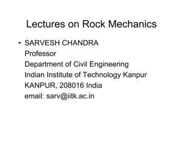
Rock Mechanics - an introduction for the practical engineerParts I, II and IIIFirst published inMining Magazine April, June and July 1966Evert HoekThis paper is the text of three lectures delivered by the author at the Imperial College ofScience and Technology, London in November 1965 as part of the University ofLondon series of Special University Lectures in Mining and Metallurgy.
Rock MechanicsRock Mechanics - an introduction for the practical engineerE. Hoek, Ph.D., M.Sc. (Eng.), B.Sc. (Eng.).Senior Chief Research Officer, Rock Mechanics Division,National Mechanical Engineering Research Institute,South African Council for Scientific and Industrial Research,Pretoria, Republic of South AfricaPart 1. Theoretical ConsiderationsIn this, the first of three articles containing extracts from a series of six lectures deliveredat the Royal School of Mines, Imperial College of Science and Technology in November1965, the author covers theoretical considerations. The other two will deal withlaboratory techniques and then with rock mechanics in the field.The purpose of this series of articles is to present some of the principles of rockmechanics to the reader who is interested in knowing something about the subject withouthaving to become too involved in technical details. The content of the articles is based,almost entirely, upon the author's own experience and, hence, does not represent acomplete review of the whole subject of rock mechanics. Consequently, the formulationof an overall rock mechanics philosophy has been assiduously avoided and the reader isleft to draw his own conclusions from the facts as they are presented.Definition and ScopeIn 1963 the Rock Mechanics Committee of the American National Academy of Scienceadopted the following definition1:Rock mechanics is the theoretical and applied science of the mechanical behaviour ofrock. It is that branch of mechanics concerned with the response of rock to the forcefields of its physical environment.It is convenient to subdivide rock mechanics into the following branches:a) Structural rock mechanics, which is concerned with the stability of engineeringstructures in which the material is predominantly rock.b) Comminution, which is concerned with the reduction of rock to small fragments bythe application of external forces as in drilling, blasting, cutting and grinding.Both these branches of rock mechanics involve the control of rock deformation andfracture processes. In the first case, excessive rock failure (in this context, failure is takento mean either excessive deformation or fracture) must be avoided in order to preservethe stability of the structure and, in the second case, rock fracture must be induced withthe minimum input of external energy. Major disasters, such as the Malpasset and2
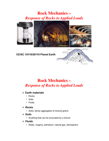
Rock MechanicsVajoint dam failures, and the Coalbrook mine disaster, serve to illustrate the importanceof rock fracture in practical engineering terms.Rock Fracture - Griffith TheoryRock mechanics research in South Africa was initiated some 15 years ago in an effort toprovide an understanding of the rockburst hazard which occurs in many deep-level goldmines.The effects of a typical rockburst are illustrated in Figure 1. It has been defined2 asdamage to underground workings caused by the uncontrolled disruption of rockassociated with a violent release of energy additional to that derived from falling rockfragments. The main causes of rockbursts are associated with the energy changesinduced by mining in the rocks surrounding large excavations and these causes have beenreviewed elsewhere2.From the rock mechanics point of view, the main characteristic of a rockburst is the factthat it occurs in hard, brittle, highly competent rocks. Consequently, in studying thefracture behaviour of these rocks, it was considered justifiable to study the behaviour ofthe rock material itself, treating it as a homogeneous, isotropic solid and ignoring theeffect of major geological discontinuities. The deficiency of this approach, when appliedto the fractured and geologically discontinuous rocks which occur on or near the earth'ssurface will be immediately obvious to the reader. Nevertheless, it is believed that anunderstanding of the basic mechanism of the fracture of rock material can be ofassistance in formulating a rational behaviour pattern for rock masses.Griffith's theory of brittle fracture3, modified by McClintock and Walsh4 to allow for thepredominantly compressive stresses in rock mechanics, has been found to provide areliable theoretical basis for the prediction of rock fracture phenomena5. This theory isbased upon the assumption that fracture initiates at inherent cracks and discontinuitieswithin the material and that propagation of these cracks occurs as a result of the tensilestress which is induced at the crack tip under load. Brace6 has shown that fracture in hardrock usually initiates in grain boundaries which can be regarded as the inherentdiscontinuities required by the Griffith theory.Griffith's original theory was concerned with brittle fracture under conditions of appliedtensile stress and he based his calculations upon the assumption that the inherent crack,from which fracture initiates, could be treated as an elliptical opening. When applied torock mechanics, in which the applied stresses are predominantly compressive, thissimplifying assumption is no longer valid and the theory has to be modified to accountfor the frictional forces which occur when the crack faces are forced into contact. Thismodification was carried out by McClintock and Walsh4 who made further simplifyingassumptions concerning the mechanism of crack closure. These simplifying assumptionshave recently been theoretically validated by Berg7 .The extent to which the modified Griffith theory defines the fracture behaviour of rock is3
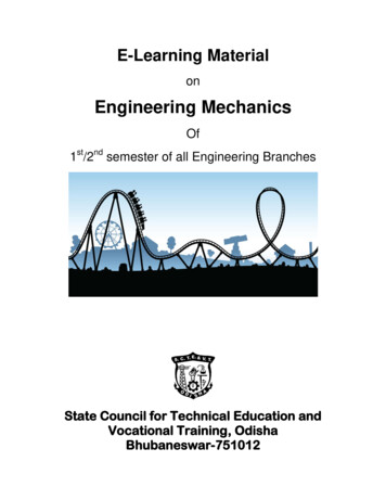
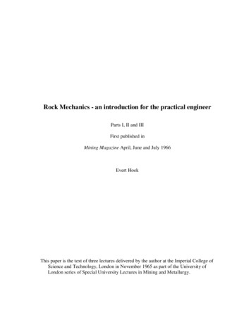
Rock Mechanicsillustrated in Figure 2. Published triaxial strength test data for the fifty rock and concretetypes listed in Table 1 are included in this graph. In order to render the test resultscomparable and to minimise differences caused by different testing techniques, specimensizes and environmental conditions, the values are plotted on dimensionless scales whichare obtained by dividing each test result by the uniaxial compressive strength of thatparticular material.A further illustration of the usefulness of the Griffith theory in defining the fracturebehaviour of hard rock is given in Figure 3. In this figure a theoretical Mohr envelope isfitted to Mohr fracture circles obtained from triaxial tests on specimens of a typical SouthAfrican quartzite.In spite of the encouraging agreement between theoretical and experimental results,illustrated in Figures 2 and 3, it would be incorrect to suggest that the Griffith's theoryprovides a complete description of the mechanism of rock fracture. It must beemphasised that its derivation is such that it is only strictly correct when applied tofracture initiation under static stress conditions5. It is largely fortuitous that it can be sosuccessfully applied to the prediction of the fracture of rock specimens since, oncefracture has initiated, propagation of this fracture and ultimate disintegration of thespecimen is a relatively complex process8, 9, 10. Fortunately, it appears that the forcesinvolved in fracture propagation are closely analogous to the friction forces assumed inthe modified Griffith theory and hence the general form of the equations which definefracture propagation is very similar to that of the equations which define fractureinitiation.Figure 1. Effects of a rockburst in a deep-level South African gold mine.4
Rock MechanicsThe original and modified Griffith theories, when expressed in terms of the stresses atfracture5, contribute little to the understanding of rock fracture under dynamic stressconditions, the energy changes associated with fracture or the deformation process ofrock. However, since the theoretical concept of fracture initiation from inherent crackshas proved so useful in describing the observed fracture behaviour of rock, this concept isbeing extended to the theoretical study of energy changes and deformation processes inrock 11, 12.The author is particularly fascinated by the belief that the processes which govern thefailure of large, fissured and discontinuous rock masses are very similar to thosewhich operate during the failure of a small rock specimen10. It is hoped that arational theoretical description of the movement of interlocking blocks of rock in alarge rock mass will eventually be built up.Additional Factors Governing FractureThe Griffith theory was derived on the assumption that the material contains a randomdistribution of uniform cracks and that the inherent physical properties of the materialremain constant. It is interesting to consider to what extent the theoretical concepts of theGriffith theory can be modified to cover cases in which the above assumptions do notapply.Fracture of anisotropic rockAn extreme example of a rock in which inherent cracks are not randomly distributed isslate. If it is assumed that slate contains two crack systems, one preferentially orientedsystem of large bedding plane cracks and one randomly oriented set of small grainboundary cracks, it becomes possible to calculate the stress levels at which fracturewould initiate under various conditions13 14.Figure 4 illustrates the remarkable agreement between the predicted and observedfracture behaviour of slate specimens subjected to uniaxial compression. It will be notedthat the highest strength of slate can be as much as four times its lowest strength,depending upon the orientation of the bedding planes to the direction of applied load.An important practical conclusion which can be drawn from Figure 4 is that a comparisonof the results obtained from compression tests on core drilled normal to and parallel to thebedding planes does not necessarily determine whether the material is anisotropic - aprocedure sometimes advocated by those concerned with "practical" tests. In the case ofslate, the compressive strength of specimens drilled normal to and parallel to the beddingplanes is almost the same, and if the strength of the specimen in which the bedding planesare oriented at 30 degrees to the direction of applied load is not taken into account, onemay be tempted to conclude that slate is isotropic. This extreme example is included todemonstrate the dangers involved in drawing conclusions from inadequate test data.5
Rock MechanicsTable 1. Summary of Triaxial Test Results on Rock and 647484950MaterialUniaxialCompressiveStrength in lb./sq.in13 70018 00020 00010 000750010 0002 3803 2006 000570035104 00025 5002420010 00033 8001 78026 00022 50057809 000**2400012 000****75 00022 00010 00048 00020 0006 00038 0008 00015 00040 000**71 00068 00083 00030 90017 10090704970430015 90037 00031 000Tested byMarbleRos and EichingerMarbleRos and EichingerMarbleVon KarmanCarthage MarbleBredthauerCarthage MarbleBredthauerWombeyan MarbleJaegerConcreteMcHenry and oncrete (28 day)BalmerConcrete (90 day)BalmerGranite GneissJaegerBarre GraniteRobertsonGranite (slightly alt)WreukerWesterly GraniteBraceIwaki SandstoneHoribe and KobayashiRush Springs andstoneBredthauerPennant SandstonePriceDarley Dale SandstonePriceSandstoneJaegerOil Creek SandstoneHandinDolomiteBredthauerWhite DolomiteBredthauerClear Fork DolomiteHandinBlair DolomiteHandinBlair DolomiteBraceWebtuck DolomiteBraceChico LimestoneBredthauerVirginia uerKnippa BasaltBredthauerSandy shaleBredthauerShaleBredthauerPorphyJaegerSiouxyr QuartziteHandinFrederick DiabaseBraceCheshire QuartziteBraceChert dyke materialHoekQuartzitic shale (Dry)Colback and WiidQuartzitic shale (Wet)Colback and WiidQuartzitic sandstone (dryColback and WiidQuartzitic sandstone (wet)Colback and WiidSlate (primary cracks)HoekSlate (secondary cracks)HoekDoleriteCSIRQuartziteCSIR(ERPM Footwall)Quartzite43 200CSIR(ERPM Hanging wall)Glass91 000CSIR** Presented in dimensionless form by McClintock and Walsh.6
Rock MechanicsFigure 2. Triaxial fracture data for 50 rock and concrete materials listed in Table 1.7
Rock MechanicsSlate is a relatively simple example of an anisotropic material, having only one set ofdominant planes of weakness. The same theoretical process as was applied in the case ofslate could be extended to describe the behaviour of a material such as coal which mayhave two or more cleat systems in addition to its bedding planes.Figure 3. Mohr fracture diagram for typical Witwaterstrand quartzite with a uniaxialcompressive strength c 30,000 p.s.i. and a coefficient of internal friction µ 1.00Figure 4. Relationship between bedding plane orientation and strength of slate8
Rock MechanicsInfluence of environment upon rock strengthIt is frequently assumed that the strength of rock is not significantly influenced by thetemperature or humidity of its surroundings. It has, however, been demonstrated that thisassumption, particularly on the influence of humidity, can be seriously in error15.The influence of temperature upon the strength of rock is probably not significant withinthe normal range of temperatures encountered by the civil or mining engineer. However,at great depths where the temperatures approach the melting point of some of the rockconstituents, the reduction in strength may be significant and could be of importance tothose concerned with the overall behaviour of the earth's crust and with the origin ofdeep-level earthquakes.The influence of moisture upon the strength of rock is so important that the authoradvocates that tests on coal and soft rocks should be carried out on site. In order tominimise changes in the moisture content of the specimen, the tests should be carried outas soon as the specimens have been removed from the parent rock. The practical detailsof this type of test will be discussed later.The influence of moisture content upon the strength of quartzitic shale is illustrated inFigures 5 and 6 which are reproduced from a paper by Colback and Wiid15. It will beseen that a saturated specimen of this quartzitic shale is only half as strong as a dryspecimen. Colback and Wiid have postulated that this reduction in strength is due to areduction in the molecular cohesive strength of the rock material when moisture ispresent.The practical importance of the influence of moisture upon the strength of rock instructural rock mechanics is the danger of a normally stable structure becoming unstablein wet conditions. In comminution, the strength reduction obtained under wet conditionsresults in more efficient cutting or drilling.Influence of fluid pressureIn addition to the strength reduction associated with a high moisture content, a furtherthreat to the stability of a rock structure occurs when water is present under pressure. Thisfluid pressure reduces the compressive stress acting across a fissure or fracture plane andhence the frictional resistance which causes interlocking of blocks of rocks can bereduced. In an extreme case, one block can be literally floated off another by thebuoyance effect of water pressure. The role of fluid pressure in determining the strengthof a rock mass is fairly well understood16 and its influence can be allowed for in strengthcalculations.The practical importance of the influence of moisture upon the strength of rock instructural rock mechanics is the danger of a normally stable structure becoming unstablein wet conditions. In comminution, the strength reduction obtained under wet conditionsresults in more efficient cutting or drilling.9
Rock MechanicsFigure 5. Relationship between uniaxial compressive strength and moisture content forquartzitic shale specimens (Colback & Wiid).1
Rock MechanicsFigure 6. Mohr fracture envelopes showing the effect of moisture on the compressivestrength of quarzitic shale (from Colback & Wiid)Influence of fluid pressureIn addition to the strength reduction associated with a high moisture content, a furtherthreat to the stability of a rock structure occurs when water is present under pressure. Thisfluid pressure reduces the compressive stress acting across a fissure or fracture plane andhence the frictional resistance which causes interlocking of blocks of rocks can bereduced. In an extreme case, one block can be literally floated off another by thebuoyance effect of water pressure. The role of fluid pressure in determining the strengthof a rock mass is fairly well understood16 and its influence can be allowed for in strengthcalculations.Time-dependent failure of rockOne of the least understood aspects of the mechanical behaviour of rock is the influenceof time upon its deformation and fracture. It is convenient to consider this subject undertwo headings:a. Weathering which is the gradual deterioration of an exposed rock surface. Thisdeterioration may take place in the absence of applied stress and is due mainly tophysical and chemical processes which are governed by the environment to whichthe rock is exposed;1
Rock Mechanicsb. time-dependent mechanical behaviour which involves the deformation or fracture ofrock under conditions of constant applied stress (frequently referred to as “creep”, aterm which the author avoids because of the possible confusion with the process ofcreep in metals which need not be the same as in rock).In most practical cases, both of these phenomena play a part and it is usually impossibleto establish which of the two is the main cause of failure.Experience in South Africa shows that coal pillars usually fail a number of years afterthey have been mined. Examination of the pillars and measurements of time-dependentdeformation suggests that both weathering and time-dependent failure are important.Consequently, one must conclude that a full understanding of the time-dependentbehaviour of rock must involve a knowledge of both weathering and time-dependentfailure. To the best of the author's knowledge, no complete and systematic study of theprocess of rock weathering has ever been undertaken and this deficiency presents aninteresting challenge to rock mechanics research workers.Time-dependent mechanical behaviour of rock has been fairly intensively investigated,both theoretically17 and experimentally18, but a great deal more remains to be done beforethis knowledge can be effectively applied to practical problems. For the engineer facedwith the problem of designing a rock structure in which weathering or time-dependentfailure may be important, the most realistic approach appears to be to use the results ofshort time laboratory tests with a liberal allowance for the possible strength reductionwith time.The extent to which the strength will reduce with time depends upon so many unknownfactors that no definite rules could be suggested but the author believes that under severeconditions, a reduction of 50 per cent over a ten year period is possible.Influence of Specimen SizeIt is accepted that the strength of a brittle material is dependent upon the size of the testspecimen and yet very little reliable quantitative data on this effect is available. In theauthor's opinion, the most rational approach to this problem is that adopted byProtodiakonov19 and his most important conclusions are presented in Figure 7.The parameter 'm', as defined in Figure 7, depends upon the nature of the material andalso upon the state of stress to which the specimen is subjected. From the fewexperimental data which are available the author has made the following estimates of thevalue of 'm':Coal and soft rocks subjected to compressionCoal and soft rocks subjected to tensionHard rock subjected to compressionHard rock subjected to tension5 m 1010 m 502 m 55 m 101
Rock MechanicsFigure 7. Relationship between specimen size and strength according to ProtodiakonovWhile these estimates must be treated with extreme caution, they do enable one to arriveat an order of magnitude for the acceptable specimen size.Hence for a material such as coal subjected to compression, the specimen size should beapproximately 50 to 100 times the spacing between discontinuities if the strength of thespecimen is to be within 10 per cent of the rock mass. Since the spacing betweendiscontinuities in may, as a first approximation, be equated to the cleat spacing which canbe in the order of 2 inches, the specimen diameter required is estimated at between 100and 200 inches.This size of specimen would daunt even the most courageous exponent of large-scaletesting and yet, if Protodiakonov's deductions and the author's estimates are reasonablyaccurate, it may have to be accepted at most tests on coal carried out on specimens whichare far too small to give meaningful results.In a series of large-scale tests planned by the Coal Mining Research Controlling Councilof South Africa in conjunction with the Council for Scientific and Industrial Research. Itis proposed to test coal specimens to 8 feet cube (the technique to be used will be1
Rock Mechanicsdiscussed later). The results of these tests should contribute towards a more reliableevaluation of the problem of the size effect in strength testing.In the case of hard rocks such as the Witwatersrand quartzites, the value of ‘m’ forcompression is believed to lie between 2 and 5 and the spacing between discontinuities,in this case assumed to be the grain boundaries, may be of the order of 1/10 of an inch.Hence, from Figure 7, the diameter of specimen required to give a strength value within10% of that for the massive rock (excluding the effect of major discontinuities) isbetween one and 2 inches.Stability of Rock StructuresIn designing a rock structures such as the damp foundation or underground excavation,the most important consideration is the stability of the entire structure. Local rock failureat the points of high stress or in zones of exceptionally low strength may only besignificant if this failure forms part of a sequence of events, which leads to collapse of thestructure.The obvious question which the practical engineer, will ask is – what are the main factorswhich govern the stability of a rock structure and what information of these factors andtheir interaction does the science of rock mechanics provide?Two main problem typesIn discussing this question it is necessary to distinguish between two main types ofstructural rock mechanics problems:a. Underground excavations in solid homogeneous rock, such as the massive quartziteswhich occur in the deep-level gold mines in South Africa, in which the stability ofthe rock surrounding the excavation is primarily dependent upon progressive failureof the rock material.b. Rock structures such as dam foundations and surface excavations in which thematerial is so faulted and fissured that the stability of the structure depends upon themovement of interlocking blocks within the rock mass rather than upon failure ofthe rock material.Progressive failure of the rock surrounding an excavationWhen a rock specimen is loaded in a hydraulically actuated testing machine, thebehaviour of the specimen at the point of fracture is obscured by the behaviour of thetesting machine. The release of the energy stored in the hydraulic system usually resultsin violent disintegration of the rock specimen with the consequent loss of all post-fracturedata. On the other hand, an elevator of rock which forms part of a rock mass and whichis subjected to an identical state of stress to that applied by the testing machine willbehave in an entirely different man out, what is the point of failure has been reached. In1
Rock Mechanicsthis case, disintegration of the rock element may be arrested by the transfer of load ontoan adjacent development, which previously carried a lower load. In this way, localfracture induces a redistribution of stress, which may or may not result in further fracture.In an attempt to understand this process of progressive failure, the author has studied theinitiation and propagation of fracture in rock under non-uniform stress conditions such asthose which occur around underground excavations20.An example of this type of analysis is presented in Figure 8 in which the theoreticalfracture contours in the rock surrounding square and elliptical tunnels are compared. Inderiving these contours it was assumed that fracture initiation in the material, assumed tobe a homogeneous quartzite, is defined by the Mohr envelope illustrated in Figure 3.This fracture criterion is combined with the stress distribution in the material surroundingthe excavations21 to give the fracture contours and the critical crack trajectories20.The fracture contours are plotted in terms of the vertical pressure P which would have tobe applied to the material surrounding the excavation in order to cause initiation offracture at any point. Hence, if the fracture contours has a value P 10,000 p.s.i., all thematerial enclosed by this contour, i.e. the material in which the fracture contours havelower values, would be prone to failure if the vertical applied pressure P was 10,000p.s.i.The vertical applied pressure P is due primarily to the weight of the overburden,increasing at a rate of approximately one p.s.i per foot of depth. The local pressure P,which acts upon a particular time or former may, however, be intensified by miningactivities in the vicinity of this tunnel Hence, at a time situated in the pillar may besubjected to a vertical applied pressure P or 15,000 p.s.i., while the pillar itself may beonly a subjected to a nominal pressure, due to its depth below the surface, of 7000 p.s.i.The critical crack trajectories define the most dangerous crack orientation at any point inthe material surrounding the tunnel. An inherent flaw or discontinuity oriented in thisdirection would fail at a lower stress level than that required to initiate failure from anyother floor, of similar size, but at a different orientation, in the vicinity.The significance of the fracture contours and critical crack to trajectories, illustrated inFigure 8, is interpreted in more practical terms in Figure 9. In both cases, the lowestfracture contour occurs in the roof (and floor) of the excavation; hence failure can beexpected to initiate at these points. Since the critical crack trajectories in this region lieparallel to the vertical access of the excavation, a vertical crack will occur as shown inFigure 9a.Experimental studies of the formation of vertical roof and floor cracks22 have shown that,apart from a redistribution of the stress and the proximity of the crack from the stabilityof excavation is not endangered by the formation of these cracks. It must also be pointedout that the tendency for these cracks to form is markedly reduced by the presence ofnatural applied stress due to the restraint of the surrounding rock23.1
Rock MechanicsThe initiation of sidewall fracture, illustrated in Figure 9b is dependent upon thegeometrical shape of the excavation. In the case of the square tunnel, the high stressconcentration in the sharp corner results in fracture initiation at a vertical applied pressureP 7500 p.s.i. The critical trajectories suggest that this fracture would propagate in sucha way that "slabbing" of the site wall would occur.The occurrence of this sidewall slabbing is illustrated in Figure 10, which shows ahaulage in quartzite at a depth of 9500 feet below surface in a South African gold mine.Figure 10a shows the haulage in an area removed from mining activity and Figure 10bshows the sidewall fracture associated with an increase in stress level due to extraction ofthe reef immediately above the haulage.Figure 8. Fracture contours and critical crack trajectories in quartzite surrounding squareand elliptical tunnels1
Rock MechanicsFigure 9. Possible fracture sequence for square and elliptical tunnels in hard quartzitesubjected to vertical pressure P only1
Rock MechanicsFigure 10a. Square tunnel in quartzite remote from mining activities. Depth of 9,500 ft.below surface in a South African gold mineFigure 10b. Sidewall slabbing in a square tunnel in quartzite which had been subjected toa pressure increase due to over-mining. Depth below surface 9,500 ft.1
Rock MechanicsIn the case of the elliptical tunnel, sitewall failure can be anticipated at P 13,000 p.s.i.And this it would probably take the form of a sidewall "scaling" as shown in Figure 9b.The fact that this scaling occurs at such high stress levels is important. Practicalexperience in deep level mines which use both square and elliptical tunnels confirms thatthe elliptical tunnel, at the same depth, has a lower tendency to sidewall failure andrequires less maintenance and support in the form of rockbolting. Evidence from modelstudies22 suggest that the next stage in failure might be associated with the stressredistribution in the roof and the floor and may follow the pattern illustrated in Figure 9.,resulting in the final fracture configurations illustrated in figure 9d.It must be emphasised that this analysis has been carried out on the assumption that theexcavations are situated in solid, homogeneous quarzite, which is subject to verticalpressure only. The presence of a fault, Fissure or marked anistropic strength behaviourwould have a significant influence upon the analysis and would invalidate theconclusions reached.A further difficulty, which has emerged from fracture studies on models20, is that thestress distribution in the rock around an excavation is drastically altered by failure ofrock. In order to overcome this difficulty, it is necessary to re-analyse the stressdistributions at each new boundary condition created by propagation of the fracture.While this form of analysis has been don
sizes and environmental conditions, the values are plotted on dimensionless scales which are obtained by dividing each test result by the uniaxial compressive strength of that particular material. A further illustration of the usefulness of the Griffith theory in defining the fracture behaviour of hard rock is given in Figure 3.