Transcription
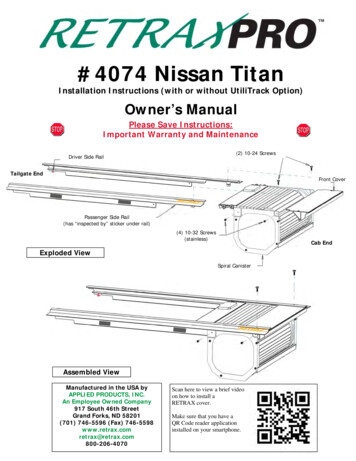
#4074 Nissan TitanInstallation Instructions (with or without UtiliTrack Option)Owner’s ManualPlease Save Instructions:Important Warranty and Maintenance(2) 10-24 ScrewsDriver Side RailTailgate EndFront CoverFront CoverPassenger Side Rail(has “inspected by” sticker under rail)(4) 10-32 Screws(stainless)Cab EndExploded ViewSpiral CanisterAssembled ViewManufactured in the USA byAPPLIED PRODUCTS, INC.An Employee Owned Company917 South 46th StreetGrand Forks, ND 58201(701) 746-5596 (Fax) 0Scan here to view a brief videoon how to install aRETRAX cover.Make sure that you have aQR Code reader applicationinstalled on your smartphone.
ASSEMBLY AND INSTALLATION INSTRUCTIONSThank you for your purchase of the RETRAX bed cover system. Please read and follow instructionsBefore un-boxing and assembling the bed cover check for shipping damage.Keep boxes and packing until installation is complete.Unpack carefully to prevent scratching. Remove protective films from cover and canister after installation is complete.REMOVE the protective plastic films before exposing to direct sunlight.DO NOT lubricate RETRAX—See Maintenance page for proper care.Parts checklist for large box Owner’s packet with keysCover rolled in to canister-spiral assemblyFront cover for canisterDrain tube kitParts checklist for rail box Tools Needed 2#Philips Screwdriver7/16” wrench9/16” wrenchDrill with 1/4” bit3/16” Allen WrenchDriver’s side railPassenger side railClamp box including (Fig #1)(2) 1/4-20 well nuts /w end removed,(2) 1/4-20 Nylock Nuts(2) 1/4-20x2” Allen Bolts(2) 1/4-20x1.5” Allen Bolts(4) G-16 Clamps(4) keyhole Rubber Spacers(4) 3” Rubber Spacers(2) 10-24x3/4” Screws1/8” measuring toolAllen wrenchDO NOT USE LOCTITE!USE OF LOCTITE VOIDSWARRANTYThe Titan comes with orwithout the Utili-Track railsystem.If the Titan does not have theUtili-track rails, then themounting hardware used isshown in Fig. 1.If the Titan does have theUtili-track rails, then themounting hardware used isshown in Fig. 2.Fig. 1Fig. 2For Titans with Utili-track system there is two ways to attach the rear of the rails to the truck:1. Drill holes and use bolts. This method will allow rail accessories to slide out the back of the track2. Use supplied clampsIf you have any questions or concerns please call 800-206-4070 or e-mail retrax@retrax.com
ASSEMBLY AND INSTALLATION INSTRUCTIONSPre-assembly guidelinesTwo people are recommended for installation and you should allow 1 to 1 ½ hours to complete.Floor space about the size of pickup box is needed for assembly of the bed cover and rails.Clear out the pickup box and clean the front and side bed rails.Plastic bed liners may have to be cut or notched at the front of the bed if they touch therolling cover or interfere with proper canister location. A jig saw with medium tooth bladeor a Dremmel or Roto-Zip tool works well. The front lip of the bed liner should be cut off ifside bed rail caps are not installed.Drain tubes (2) 1/2" drain tubes connect to the bottom of canister and can exit out the floor at thefront of the pickup bed. There are small drain holes in the front corners of the floor in the Titan.These can be enlarged to 1/2” and used for the drain tubes. For pickups equipped with plasticbed-liners, holes for the drain tubes need to be drilled through the plastic only. We recommenddrilling additional holes through the floor of a plastic bed liner at the lowest points in front to allowfor water drainage.STEP 1 Remove the shipping bracket and yellow wire.Completely remove white shipping tubes.Shipping tubeThe shipping brackets can bedisassembled simply by removal ofthe 10-32 screws fastened to each sideof the canister (Remove these itemsonly). The tailgate can thenbe lifted away from the canister allowingfor the removal of the shipping bracketby sliding the T-channel out from thewire ties. The wire ties can then beremoved from the bearings without theneed for cutting the wire. Pull whiteShipping tubes completely out of thecanister.DO NOT ALLOW THE COVER TOROLL INTO THE SPIRAL BECAUSETHE BOTTOM OF THE LOCK CANDAMAGE THE COVER!Shipping bracketRemove these items only!Driver’s side view of assembly
ASSEMBLY AND INSTALLATION INSTRUCTIONSSTEP 2 Install the passenger rail to the spiral.Passenger rail has “inspected by” sticker under the front of the railLift up the lock cover and open lock by pressing release button.Front attachment holeBearings enterchannel of railhere.Rear attachment holeStart sliding the cover and bearingsinto the channel of the rail.View from drivers sideSlide the rail over thecover until the twothreaded holes in therail are lined up behindthe two holes in thespiral. Attach using twoof the 10/32 by 7/16"screws.Tighten using amanual #2 Phillipsscrewdriver.DO NOT USE LOCTITE!USE OF LOCTITE VOIDS WARRANTYView from passenger side
ASSEMBLY AND INSTALLATION INSTRUCTIONSSTEP 3 Install the drivers rail.Lift up the lock cover and open lock by pressing release button.Pull the cover out of the canister 6”-8” (See PowertraxPRO Installation Supplement on how tomove electric cover). Caution: DO NOT allow cover to roll back into canister until rail is installed.Repeat Step #2 to install the driver's rail. Be sure all rail mounting screws are tight.SIDE VIEW OF FRONT COVERSTEP 4 Install the frontcover. The front cover isattached below the rails.Hold the cover level and pushboth ends in evenly to helpslide it into place. When theholes are lined up, startthreading the (2) Front Covermounting screws Tightenthe 2 screws securely using amanual #2 Phillips screwdriveror the enclosed 1/8” Allenwrench.This end towards tailgateWeather-strip towards cabFront CoverSTEP 5 Lift the assembled cover into thebed. Roll the cover into the canister and pushdown firmly on the rounded end of the lock until itlatches. Close the tailgate on the pickup. Using twopeople, lift the bed cover by the front of the railand two feet to the back. Set the assembly in placeat the very front of the bed.The rubber weather-strip on the frontcover should lie on top of the pickup’sfront rail - pointed towards the cab.(NOTE: If needed, gently push and twist the railsslightly inward to drop into place.)A latch is found on a Manual Cover Only. SeePowertraxPRO Installation Supplement onhow to mover electric cover.Lift bed cover at these points
ASSEMBLY AND INSTALLATION INSTRUCTIONSSTEP 6 Position thecover. Move the railsforward or back to achievean 1/8" gap between thebottom notch of the railand the inside face of theclosed tailgate or tailgateprotector. Measure bothsides. Use the supplied1/8” thick measurementtool to achieve the correct1/8" gap.1/8” gaphereDriver’s side RailTailgateProtectorNote: Plastic bed liners may have to be cut at thefront of bed so the bed cover can be moved forwardto achieve proper 1/8” clearance at the tailgate.TailgateNote: Keep rails from movingonce in position 1/8" from thetailgate.Steps 7 and 8 are for Titan’s without the Utili-track systemSteps 7-U and 8-U (next page) for Titan’s with Utili-track systemSTEP 7 Install the front set ofclamps. Start with the two clamps closest to the canister. Proper clamp location isover the rail spacer blocks.The clamps should be installed as high upas possible to engage more teeth on therail. Using a 9/16” wrench, tighten theclamps. If the clamp wants to rotate whiletightening, hold with pliers or vice-grip.STEP 8 Install the rear set of clamps. Attach the rearset of clamps over the rail spacer blocks at the rear of the rail.Push down on the rail as you tighten the clamp bolts for a better seal on top of the pickup box rails.The rear of the rail may need to be tilted up or down for best fitover the tailgate or tailgate protector.
ASSEMBLY AND INSTALLATION INSTRUCTIONS**If your truck has the Utili-track option use Step 7-U and 8-U**Step 7-U: Drill the front mounting holes in thebed. There are 3 holes near the canister in eachrail. The Titan Crew cab 7 ’ long bed uses the holenearest to the canister. The King cab 6.5’ bed usesthe middle hole. The Crew cab 5.5’ bed uses therear hole. Hold the drill level and drill 1/4” holesthrough the center of the front mounting holes inthe rails and through the pickup bed rails. (The Titan King cab 8’ long bed has 1 hole near the canisterand one additional hole in the middle of the rail)TitanCrew5.5’TitanKing6.5’Step 8a-U: Attach the bed cover to thepickup. Start at the front. Insert the Allenhead bolts (1/4-20x2) through the correct holein the rail and start threading and tighten thebolt into the rubber well nuts. Hold the rubbernut with the end of you fingers behind theUtili-track rails.Hold drill levelStep 8b-U: Attach rear of the rails to the pickup.Fasten the clamps over the spacers at the rear of both rails.Hold rails level when tightening clamps.To bolt the rails in place, hold the drill level and drill 1/4” holes throughthe center of the rear mounting holes in the rails and through thepickup bed rails. Insert the Allen head bolts (14-20x1.5”) into thepredrilled holes on the rails and thread into 1/4-20 Nylock nuts.Reminder: The bolt method allows accessories to slide out the rear.Additional Notes for use with Utili-track Options: The lock handle needs to be pushed part way down for clearance whenrolling the bed cover over the bed divider option. You may also need to liftup slightly on the cover for additional clearance when passing over the beddivider. If needed the bed divider can be lowered for clearance. You canoblong the 2 holes on both mounting brackets to lower the divider 1/8” to1/4”.The knobs for the bed extender may need to be turned slightly for clearance. We do have smaller knobs available from the factory. Call us toorder them. (The knobs have either 8mm or 10mm threads-please measure before ordering.)The bed extender can be narrowed if it makes contact with the inside edgeof the bed cover rails. Completely loosen the screws shown to the rightand slide the extender together about 1/4”, then retighten.TitanCrew7’Insert the bolts through railholes and thread into thecut end of the rubber nut.
ASSEMBLY AND INSTALLATION INSTRUCTIONSSTEP 9 Measure the distance between the rails.The rails must be the same distance apart from each other(parallel) from the front to the rear. The following stepsshow how to measure and adjust the rails. Measurements aretaken at 3 places starting at the front. The photo to the rightshows measurement being taken with a tape measure.Measurements are takenhere at the top of the railsDrivers railrear view(right above the weather-stripping)Passenger railrear viewSTEP 9 a. Measure and record the distance betweenthe rails at A - next to front cover screws.A This is your base measurement.Cover rolled into canisterLock9 b. Measure and record the distance at Babove the front clamps or above the frontAllen bolts. (with clamps or Allen bolts tight)B TOP VIEW9 c. Measure and record the distance at Cabove the rear clamps or above the rear Allenbolts. (with clamps or Allen bolts tight)C If the measurements at B and C are notthe same as A then adjustmentsare needed. See STEP 10.Step 10: Adjust the distance between the tworails of the rolling cover. To adjust the distancebetween the rails, the Allen bolts will have to beloosened or the clamps removed. The distance betweenthe rails is reduced by adding rubber rail adjustmentspacers to the rubber blocks behind the bolts orclamps. Slide the rubber spacers between the rubberblock and the pickup bed rail caps. Each rubber spacerwill decrease the distance by approximately 1/8”.Continue adjustment until the rails are parallel at thefront and rear mount locations when clamps or boltsare tight.Tailgate
ASSEMBLY AND INSTALLATION INSTRUCTIONSSTEP 11 Check for proper fit between thefront cover and the rolling cover. Using thelock handle, pull the cover closed over thetailgate and latch. The amount of weatherstrip showing at the front of the rolling covershould be close to equal on both thepassenger and drivers sides. (Photo showsunpainted parts for clarity) If there is lessweather-strip exposed on one side, adjustthat rail by removing the clamps and movingthat rail towards the cab. Replace theclamps and close the cover. Check again forequal spacing at the front and readjust ifneeded.Driver’s side view — Front of pickup boxSTEP 12 (a)Remove plastic film fromthe canister. Place thefoam washers over thedrain tube fittings. Pushthe assembled tubes intothe 2 holes on the bottomof the canister. The fittingshould lock into place; testby pulling down on thefitting, it should not pullout of canister.Foam washerDrain tube fittingDrain tubeSTEP 12 (b) Finish installing the drain tubes. On some models there are factory drain holes in both frontcorners, on others there are plastic plugs that can be drilled out for the tubes. You can enlarge existingholes or drill new holes in the front wall or floor if needed. Be careful of what is behind when you drill. Ifusing a plastic bed liner, then holes need to be drilled through the liner only. Cut the tubes to length to fitin desired locations.STEP 13 Open and close the cover to insure it is rolling without rubbing or binding. Now remove theplastic films from the cover. (Remove film before exposing to the sun)FINAL NOTES: Be sure that all clamps or bolts are tight. The top surface of the rails should be level.Loosen the clamp, adjust rail and retighten clamp if needed. On some models, a better fit over the tailgate or tailgate protector maybe obtained if the rear of the rail is tilted up or down slightly. You should beable to open and close easily. The rolling resistance will decrease over time as the weather-stripping andbearings break-in.The lock will push down easily when the cover is completely closed at the tailgate. You also will be ableto latch and lock the cover anywhere else along the rail by pushing down firmly on the rounded endof the lock handle. In any part way open position; two thumbs may be needed to latch the cover inplace. The effort needed to latch the cover will decrease as the lock mechanism takes a set. The lockcan be adjusted if needed. At the bottom of the lock is an adjustable steel tip that contacts the rail. Toincrease or decrease the pressure, loosen the jam nut with a 7/16” wrench, adjust the steel tip in or outwith an 1/8” Allen (hex) head wrench, then hold steel tip while re-tightening the jam nut.DO NOT lubricate the RETRAX bed cover!See maintenance on back page
RetraxPRO MAINTENANCE AND USE INSTRUCTIONSUSEThe Retrax cover has superior quality, rail weather-strip seals. These seals help minimize water intrusion into the pickupbed. The initial break-in period for the rail weather-strip is about 48 hours in the fully closed position. Your cover may beslightly harder to open and close during the break-in period.1Opening and Using the CoverUsing your RetraxPRO cover is as simple as opening thelock cover and pressing the button at the center of thelatch to pop open the handle (1). If properly installed, thecover should be able to roll open and closed easily withone hand (2). During the break-in period more effort maybe needed, but you still should be able to roll the coveropen and closed with one hand.2Closing and Locking the CoverTo latch your RetraxPRO coveranywhere along the rail, push downfirmly on the end of the lock handle usingboth thumbs (3). It takes this amount offorce because it is a friction lock in anyopen position. The RetraxPRO cover iseasier to latch in the fully closed positiondue to a recess in the rail.Securing Loose Cargo3The teeth of the RETRAX keys always face out4RetraxPRO covers make transportingloose and large pieces of cargo safe andsecure; a unique feature that mosttonneau covers cannot claim.To secure any item too big to fit under thecover, latch the lock handle shut againstthe item to help keep it in place (4).LockedPositionMAINTENANCE & CARECleaning and Caring for Your CoverTreat your RetraxPRO cover like you would treat the hood of your truck; you canwash and wax your cover like you would your pickup. The weatherstripping on yourcover may absorb soapy residue from a car wash, so we recommend wiping downthe inside of your rails from time to time (5).Important:NEVER spray any lubricant or cleaner in the rails. This will void your warranty. Theball bearings are sealed and will not need any sort of lubricant or spray.5UnlockedPosition
Warranty StatementApplied Products, Inc. (referred to as manufacturer) warrants each new RetraxPRO retractable pickup bedcover to the original owner as follows:The RetraxPRO has a limited life me warranty for the failure of materials and workmanship. Warrantyreplacement costs will be prorated a er three (3) years.Items not covered under the warranty:‐Normal wear over the life of the RetraxPRO‐Water intrusion at any loca on or any damage caused as a result‐Other dealer and/or purchaser installed parts & accessoriesCondi‐‐‐‐‐‐‐‐ons which will void all warranty:Lubrica on of the rails or sealed ball bearingsAltering the RetraxPRO in any manner without wri en approval from the manufacturerUse for any purpose other than the normal intended useMisuse, negligence or accidentInstalla on of any other part or accessory which comes in contact with or may interfere with theRetraxPRO without wri en approval of the manufacturerFailure to register this warranty with the manufacturer within thirty (30) days from the date ofdeliveryFailure to adequately secure cargo to prevent damage to the RetraxPROActs of God or other external causesCondi ons and Limita onsThis warranty is subject to certain condi ons and limita ons including, but not limited to, the following:‐Any part of a RetraxPRO retractable pickup bed cover that is found to be defec ve under the termsof this warranty will be repaired or replaced using either new or recondi oned parts at the discre onof the manufacturer.‐In determining what cons tutes a failure under the terms of this warranty the decision of themanufacturer will be final.‐This warranty is applicable to the original purchaser only and is not transferable to subsequentpurchasers.‐The manufacturer does not accept any responsibility in connec on with the installa on of any of itsproducts by its dealers or agents.
‐‐‐‐The manufacturer does not undertake responsibility to any purchaser for warranty express orimplied by any of its dealers, distributors or agents beyond which is contained herein.Without regard to an alleged defect of its products the manufacturer under any circumstances doesnot assume responsibility for loss of me, inconvenience, revenue, or other consequen al damageincluding, but not limited to, expenses for telephone, food, lodging, travel, loss or damage to thevehicle the products are installed on or loss or damage to personal property of the purchaser or userof the products.The manufacturer reserves the right to make changes in the design of, improvements to, or warrantyof its products without imposing any obliga on upon itself to provide the same for any productstheretofore manufactured.Under no circumstances shall Applied Products, Inc. be liable for special, indirect, incidental orconsequen al damages sustained in connec on with the RetraxPRO coverSome states do not allow limita ons on how long the implied warranty lasts, so the aforemen onedlimita ons may not apply to you.Claim ProcedureIf a part fails, the purchaser should return to the selling dealer to determine if the failed part is coveredunder the terms of this warranty. If a warranty claim is necessary, the dealer will contact Applied Products,Inc. If it is imprac cal for the purchaser to return to the selling dealer, then the purchaser may contactApplied Products, Inc. directly at 1‐800‐206‐4070. The defec ve part, along with a copy of the original bill ofsale, must be returned prepaid to Applied Products, Inc. at 917 S. 46th St. Grand Forks, ND 58201. At themanufacturer’s discre on, photos, a copy of the original bill of sale and the serial number may be submi edin lieu of the returned damaged product to Applied Products, Inc. A er determining the validity of thewarranty claim, Applied Products, Inc. will ship a replacement part prepaid to the customer. Labor costs toreplace defec ve parts are the responsibility of the purchaser.If at any me you need warranty assistance, please call 1‐800‐206‐4070 or email us at retrax@retrax.comand one of our technical reps will be happy to help you. When calling or emailing, please be prepared toreference your part number and serial number.An Employee Owned CompanyRetraxPRO– Manufactured by Applied Products, Inc., 917 S 46th St., Grand Forks, ND ��5596—FAX (701) 746‐5598Made in the USA
Tools Needed 2#Philips Screwdriver 7/16" wrench 9/16" wrench Drill with 1/4" bit 3/16" Allen Wrench Fig. 2 Fig. 1 For Titans with Utili-track system there is two ways to attach the rear of the rails to the truck: 1. Drill holes and use bolts. This method will allow rail accessories to slide out the back of the track .