Transcription
AePlace: Electrostatics based Placement using Fast Fourier Transformand Nesterov’s MethodJINGWEI LU, University of California, San DiegoPENGWEN CHEN, National Chung Hsing UniversityCHIN-CHIH CHANG, Cadence Design Systems, Inc.LU SHA, Cadence Design Systems, Inc.DENNIS JEN-HSIN HUANG, Cadence Design Systems, Inc.CHIN-CHI TENG, Cadence Design Systems, Inc.CHUNG-KUAN CHENG, University of California, San DiegoWe develop a flat, analytic and nonlinear placement algorithm eP lace, which is more effective, generalized,simpler and faster than previous works. Based on the analogy between placement instance and electrostaticsystem, we develop a novel placement density function eDensity, which models every object as positivecharge and the density cost as the potential energy of the electrostatic system. The electric potential and fielddistribution are coupled with density using a well-defined Poisson’s equation, which is numerically solvedby spectral methods based on fast Fourier transform (FFT). Instead of using the conjugate gradient (CG)nonlinear solver in previous placers, we propose to use Nesterov’s method which achieves faster convergence.The efficiency bottleneck on line search is resolved by predicting the steplength using a closed-form equationof Lipschitz constant. The placement performance is validated through experiments on the ISPD 2005 andISPD 2006 benchmark suites, where ePlace outperforms all state-of-the-art placers (Capo10.5, FastPlace3.0,RQL, MAPLE, ComPLx, BonnPlace, POLAR, APlace3, NTUPlace3, mPL6) with much shorter wirelengthand shorter or comparable runtime. On average of all the ISPD 2005 benchmarks, ePlace outperforms theleading placer BonnPlace with 2.83% shorter wirelength and runs 3.05 faster. On average of all the ISPD2006 benchmarks, ePlace outperforms the leading placer MAPLE with 4.59% shorter wirelength and runs2.84 faster.Categories and Subject Descriptors: B.7.2 [Integrated Circuits]: Design Aids; J.6 [Computer-Aided Engineering]: Computer-aided design (CAD)General Terms: Design, Algorithms, PerformanceAdditional Key Words and Phrases: Electrostatics, density function, analytic placement, nonlinear optimization, Poisson’s equation, spectral methods, fast Fourier transform, Nesterov’s method, preconditioning.ACM Reference Format:Jingwei Lu, Pengwen Chen, Chin-Chih Chang, Lu Sha, Dennis Jen-Hsin Huang, Chin-Chi Teng, and ChunThis article is partially based on our prior works ”FFTPL: An Analytic Placement Algorithm Using FastFourier Transform for Density Equalization”, which is published in IEEE 10th International Conferenceon ASIC (ASICON 2013), and ”ePlace: Electrostatics based Placement using Nesterov’s Method”, which ispublished in IEEE/ACM 51st Design Automation Conference (DAC 2014).Author’s addresses: J. Lu, Department of Computer Science and Engineering, University of California, SanDiego, 9500 Gilman Drive, La Jolla, CA 92093, jlu@cs.ucsd.edu. P. Chen, Department of Applied Mathematics, National Chung Hsing University, No. 250, Guoguang Rd, Nan District, Taichung City, Taiwan402; C.-C. Chang, L. Sha, D. J.-H. Huang and C.-C. Teng, Cadence Design Systems, 2655 Seely Avenue,San Jose, CA 95134, {chinchih,lusha,dhuang,ccteng}@cadence.com.; C.-K. Cheng, Department of ComputerScience and Engineering, University of California, San Diego, 9500 Gilman Drive, La Jolla, CA 92093,ckcheng@ucsd.edu.Permission to make digital or hard copies of part or all of this work for personal or classroom use is grantedwithout fee provided that copies are not made or distributed for profit or commercial advantage and thatcopies show this notice on the first page or initial screen of a display along with the full citation. Copyrightsfor components of this work owned by others than ACM must be honored. Abstracting with credit is permitted. To copy otherwise, to republish, to post on servers, to redistribute to lists, or to use any componentof this work in other works requires prior specific permission and/or a fee. Permissions may be requestedfrom Publications Dept., ACM, Inc., 2 Penn Plaza, Suite 701, New York, NY 10121-0701 USA, fax 1 (212)869-0481, or permissions@acm.org.c YYYY ACM 1539-9087/YYYY/01-ARTA ACM Transactions on Embedded Computing Systems, Vol. V, No. N, Article A, Publication date: January YYYY.
A:2J. Lu et al.Kuan Cheng, 2014. ePlace: Electrostatics based Placement using Fast Fourier Transform and Nesterov’sMethod. ACM Trans. Embedd. Comput. Syst. V, N, Article A (January YYYY), 32 01. INTRODUCTIONPlacement plays an important role in the VLSI physical design automation [Kahnget al. 2010; Lu 2010] for both random logic [Lu et al. 2013] and datapath intensive components [Zhuang et al. 2013]. Placement performance largely impacts the downstreamstages of power grid design [Wang et al. 2013], clock tree synthesis [Lu et al. 2012a],power optimization [Lu et al. 2012b], global detail routing [Lu and Sham 2013], postlayout simulation [He et al. 2012] and design variability [Zheng et al. 2014]. As thetechnology node enters the deep nanometer scale [ITRS 2011] with billion-transistorintegration, the performance of the placement engine becomes dominant on the overallquality of the design. Lots of research works on placement have been proposed in therecent years [Markov et al. 2012]. The quality of placement results is usually evaluated by the total half-perimeter wirelength (HPWL), which correlates with timing [Luet al. 2010] and routability [Sham et al. 2009; Han et al. 2011]. HPWL is widely used inmodern research developments [Kim and Markov 2012; Kim et al. 2012; Viswanathanet al. 2007a; Chen et al. 2008; Kahng and Wang 2006; Kim et al. 2010; Viswanathanet al. 2007b; Chan et al. 2006] and public placement contests [Nam et al. 2005; Nam2006].Traditional placement methods can be generally divided into four categories, namely(1) stochastic simulation (2) min-cut partition (3) quadratic minimization (4) nonlinearoptimization, respectively. Stochastic approaches are usually based on simulatedannealing techniques, of which one representative work is Timberwolf [Sechen andSangiovanni-Vincentelli 1986]. Uphill climbing is probabilistically accepted to rescuethe placer from local optima. Despite high solution quality, stochastic placement hashigh complexity and low convergence rate, which induces poor scalability to large circuits. Min-cut approaches recursively simplify the problem by partitioning the instance (netlist and placement region) into smaller sub-instances. Local optimum algorithms [Caldwell et al. 2000] are usually employed when the problem instancebecomes sufficiently small. State-of-the-art works include Capo [Roy et al. 2006],Dragon [Taghavi et al. 2005] and Fengshui [Agnihorti et al. 2005]. However, improperpartitioning at early stages could induce unrecoverable quality loss to the final solution. Quadratic approaches approximate the net length using a quadratic function,which can be linearized by various net models [Spindler et al. 2008]. The differentiability enables gradient-based minimization techniques [Press et al. 2007]. Densityequalization is performed by adding pseudo pins and nets to the physically overlappedcells with a linear term introduced to the cost function [Eisenmann and Johannes1998]. By solving the linear system, cells are iteratively dragged away from over-filledregions. State-of-the-art quadratic placers include FastPlace3.0 [Viswanathan et al.2007b], RQL [Viswanathan et al. 2007a], SimPL [Kim et al. 2010], MAPLE [Kim et al.2012], ComPLx [Kim and Markov 2012], BonnPlace [Struzyna 2013] and POLAR [Linet al. 2013]. Despite high placement efficiency, the solution quality and robustnessusually lag behind nonlinear placers. Nonlinear approaches refer to the algorithmsbased on a framework of nonlinear optimization. Wirelength and density are modeled using smooth mathematical functions thus gradients can be analytically calculated. Wirelength models mainly include the log-sum-exp model [Naylor et al. 2001]and the weighted-average model [Hsu et al. 2011]. Density models mainly include thebell-shaped function [Naylor et al. 2001], Gaussian equation [Chen et al. 2008] andHelmholtz equation [Chan et al. 2005]. The partial differential equation (PDE) can besolved by Green’s function [Cong et al. 2008] or finite-difference method [Chan et al.ACM Transactions on Embedded Computing Systems, Vol. V, No. N, Article A, Publication date: January YYYY.
ePlace: Electrostatics based Placement using Fast Fourier Transform and Nesterov’s MethodA:32005]. By Lagrange relaxation or penalty method, the grid density constraints are integrated into the objective function and solved by nonlinear CG method. State-of-the-artnonlinear placers include APlace3 [Kahng and Wang 2006], NTUPlace3 [Chen et al.2008] and mPL6 [Chan et al. 2006]. Due to the high complexity of modeling functions,nonlinear approaches employ multi-level cell clustering to simplify the problem andaccelerate the algorithm. However, the quality overhead is not negligible.In this work, we develop a flat analytic algorithm eP lace [Lu et al. 2014] for nonlinear global placement. ePlace is more effective, generalized, simpler and faster thanprevious approaches. In contrast to the multi-level framework in prior nonlinear placers, our algorithm conducts placement on the flat netlist. Moreover, we develop a noveldensity function eDensity [Lu et al. 2013] modeling the placement instance as an electrostatic system for density equalization. Unlike hierarchical density grid structuresused in pror works, ePlace sticks to a flat density grid with constantly high resolution.Compared to previous nonlinear placers [Kahng and Wang 2006; Chan et al. 2006;Chen et al. 2008], ePlace avoids quality loss due to suboptimal cell clustering and lowdensity resolution, especially at early placement iterations. The density function is formulated as the system potential energy, while the density gradient is defined to be theelectric repulsive force. A modified Poisson’s equation is proposed to couple the chargedensity with electric potential and field distribution, Neumann boundary condition isenforced to maintain the legality of the global placement solution. Based on the abovedefinition, a fast numerical method is proposed to solve Poisson’s equation using spectral methods [Skollermo 1975], it well satisfies the boundary condition and makes thelocal density gradient aware of global density information. The time complexity is onlyO(m log m) where m is the total number of movable elements. Besides, we propose touse Nesterov’s method [Lu et al. 2014] for the nonlinear placement optimization. Thesteplength is determined as the inverse of the Lipschitz constant, which is dynamically predicted without computation overhead. The placement efficiency is improvedby more than 2 compared to the CG method (with line search). We further enhancethe performance of the nonlinear solver using a preconditioning technique to staticallyapproximates the Hessian matrix of the objective function. All the above innovationsare integrated into the flat nonlinear placement algorithm ePlace, which is validatedthrough experiments on the ISPD 2005 [Nam et al. 2005] and ISPD 2006 [Nam 2006]benchmark suites with high placement quality and efficiency achieved.The remainder of the paper is organized as follows. In Section 2, we review the previous nonlinear placement works and discuss the existing problems. In Section 3, wediscuss the analogy of placement instance to the electrostatic system as well as theformulation of the density penalty and gradient. We propose a well-defined Poisson’sequation in Section 4 with a fast numerical solution based on spectral methods. InSection 5, we propose to use Nesterov’s method for solving the nonlinear placementproblem with dynamic prediction of the Lipschitz constant and discuss our preconditioning technique. In Section 6, we discuss our global placement algorithm ePlace,which is empirically validated in Section 7. We conclude the work in Section 8 anddiscuss future research directions.2. ESSENTIAL CONCEPTS OF PLACEMENT AND PRIOR NONLINEAR ALGORITHMSIn this section, we introduce the essential concepts and problem formulation of analytic global placement. We then discuss the basic methods and existing problems ofthe prior nonlinear optimization algorithms.2.1. Essential Concepts of PlacementA placement instance is formulated as a hyper-graph G (V, E, R), where V denotesthe set of vertices (cells), E denotes the set of hyper-edges (nets) and R denotes theACM Transactions on Embedded Computing Systems, Vol. V, No. N, Article A, Publication date: January YYYY.
A:4J. Lu et al.placement region, respectively. We use Vm and Vf to denote the movable cells andfixed macros in the node set V . Let n Vm denote the number of movable placementobjects. A legal solution satisfies the following three requirements.— Every cell is accommodated using enough free sites in the placement region.— Every cell is horizontally aligned with the boundaries of one placement row.— There is no overlap between cells or macros.Based on the legality constraint, a placer targets minimizing the total HPWL of allthe nets. Let v (x, y) denote a placement solution, where x {xi i Vm } and y {yi i Vm } are the horizontal and vertical coordinates of all the cells. The HPWL ofeach net e is denoted as HP W Le (v) and defined in Eq. (1).HP W Le (v) max xi xj max yi yj .i,j ei,j eThe total HPWL is then computed as HP W L(v) placement problem defined in Eq. (2).Pe E(1)HP W Le (v) and we have themin HP W L (v) s.t. v is a legal solution.v(2)2.2. Definition of Global PlacementGlobal placement is usually regarded as a problem of constrained optimization. Theplacement region is uniformly decomposed into a set of m m rectangular grids (bins)denoted as B. Based on a placement solution v, let ρb (v) denote the density of eachgrid b as expressed in Eq. (3).Xρb (v) lx (b, i)ly (b, i).(3)i VHere lx (b, i) and ly (b, i) denote the horizontal and vertical overlaps between the grid band the cell i. Both lx (b, i) and ly (b, i) exhibit a rectangular shape, which is not differentiable at boundary points. As Eq. (4) shows, a global placement problem targets asolution v with minimum total HPWL subject to the constraint that the density ρb (v)of all the grids are equal or below a predetermined target placement density ρt .min HP W L (v) s.t. ρb (v) ρt , b B.(4)v2.3. Wirelength SmoothingAs Eq. (1) shows, the wirelength function HP W L(v) is not differentiable and hard tominimize. As a result, various smoothing techniques have been developed to improvethe differentiability thus convergence rate. Here we only discuss the horizontal part ofthe wirelength smoothing function while the vertical part can be obtained in a similarway.Log-Sum-Exp (LSE) wirelength model is proposed in [Naylor et al. 2001] and widelyused in recent nonlinear placers [Chan et al. 2006; Chen et al. 2008; Kahng and Wang2006]. For each net e {(x1 , y1 ), (x2 , y2 ), . . . , (xn , yn )} with n pins, the LSE functionapproximates the horizontal span HP W Le as Eq. (5) shows.We (v) γlnXi eexp„xiγ« lnXi eexp„ xiγ«!.(5)ACM Transactions on Embedded Computing Systems, Vol. V, No. N, Article A, Publication date: January YYYY.
ePlace: Electrostatics based Placement using Fast Fourier Transform and Nesterov’s MethodA:5Here γ is the smoothing parameter, which can be used to control the modeling accuracy1 . As discussed in [Wang et al. 2009], the modeling error is upper-bounded byεLSE (e) γ ln n.Weighted-Average (WA) wirelength model is proposed in [Hsu et al. 2011]. Eq. (6)shows the horizontal function of net eWe (v) Pi ePxi exp (xi /γ)i eexp (xi /γ)Pi e Pxi exp ( xi /γ)i eexp ( xi /γ)!,(6)where similarly γ is used for accuracy control. [Hsu et al. 2011] shows that the modγ xeling error is upper-bounded by εW A (e) 1 exp x/n , which is roughly half of that ofεLSE (e). In this work, we use the WA wirelength model for our nonlinear placementoptimization.2.4. Density PenaltyAs Eq. (4) shows, a legal global placement solution requires all the B grid densityconstraints to be satisfied simultaneously, where B could be of million-scale or evenlarger at modern IC design. As a result, all the constraints are usually cast into asingle penalty function N (v) as shown in Eq. (7). By definition, all the B densityconstraints will be satisfied if and only if we have N (v) 0.ρb (v) ρt , b B N (v) 0.(7)Quadratic placement approaches usually model the density penalty as a linear orquadratic function, which can be easily integrated into their objective function. Thepenalty in UPlace [Yao et al. 2005] is explicitly devised as a weightedP sum of all the frequency components of the density function. Specifically, N (v) u,v wu,v a2u,v , whereu and v are the discrete frequency indexes, wu,v are the weight factors and au,v are thefrequency coefficients. Notice that each frequency component is a differentiable wavefunction, of which the smooth curve can help direct gradient-based optimization in aneffective way. The above penalty is fitted into a quadratic form and integrated into theobjective function. Other quadratic placers [Eisenmann and Johannes 1998; Spindleret al. 2008; Viswanathan et al. 2007b; Kim et al. 2012; Kim and Markov 2012; Linet al. 2013] modify the netlist by introducing anchor points, which implicitly producethe density penalty terms for the quadratic cost function.Nonlinear placers have no constraints on the order of modeling functions thus areable to design the penalty in more flexible ways. APlace3 [Kahng and Wang 2006] andNTUPlace3 [Chen et al. 2008] use a quadratic penalty function with respect to griddensity as Eq. (8) showsX2N (v) (eρb (v) ρt ) .(8)b BAs the original density function ρb (v) is not differentiable and hard to optimize, asmoothed density function ρe is used here by employing a “bell-shape” local smoothingtechnique [Naylor et al. 2001]. In contrast to the penalty method as discussed above,mPL6 [Chan et al. 2006] directly applies Lagrange multipliers to all the density constraints. The density function in [Chan et al. 2006] is smoothed in a global scale byusing Helmholtz equation (Eq. (7) in [Chan et al. 2005]).In this work, we model the placement instance as an electrostatic system and devisethe density penalty N (v) to be the system potential energy. In the remaining part of1 TheHPWL smoothing parameter γ cannot be set to arbitrarily small due to the computation precisionconstraint.ACM Transactions on Embedded Computing Systems, Vol. V, No. N, Article A, Publication date: January YYYY.
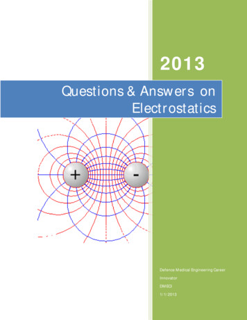
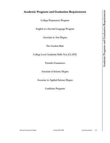
A:6J. Lu et al.the paper, we will use N (v) to denote both density penalty and system energy. Thismodeling methodology is discussed in detail in Section 3 regarding how the densitypenalty and gradient are defined. A fast numerical solution to the density and potentialrelated Poisson’s equation (Eq (20)) is proposed in Section 4.2.5. Nonlinear Optimization FormulationBased on the smooth wirelength function W (v) and density penalty function N (v),nonlinear global placers [Chen et al. 2008; Kahng and Wang 2006] formulate the objective function f (v) using a penalty factor λ as followsmin f (v) W (v) λN (v).v(9)As both the wirelength function and the density penalty are smoothed thus differentiable, gradient-based optimization methods [Shewchuk 1994] are used in prior nonlinear placers [Chen et al. 2008; Kahng and Wang 2006] to produce high-quality numerical solutions. Alternatively, Lagrange multipliers are also used [Chan et al. 2006]to formulate the objective function in a different form as belowXmin f (v) W (v) λb eρb (v) ρt .(10)vb BHere λb denotes the multiplier on the density constraint of the bin b. This approachmight consume longer runtime due to the computation demand on the multipliers.Multi-level cell clustering is employed in all the previous nonlinear placers [Chan et al.2006; Chen et al. 2008; Kahng and Wang 2006] to accelerate the placement algorithm.Despite efficiency improvement, the quality overhead due to sub-optimal clustering isnot negligible.3. EDENSITY: A NOVEL DENSITY FUNCTION BY ELECTROSTATIC SYSTEM MODELINGWe propose a novel formulation of the density penalty and gradient function, eDensity,by modeling the entire placement instance as a two-dimension independent electrostatic system. The distribution of electric potential and field is determined by all theelements in the system. Each node i (a cell or a macro block) in the netlist is transformed to a positively charged particle (also denoted as i). The electric quantity qi ofthe particle is set to be the node area Ai . The motion of a movable cell i is driven by theelectric force Fi qi ξ i formulated by Lorentz force law, where ξi is the local electricfield. Similarly, the cell potential energy Ni is calculated as Ni qi ψi where ψi is theelectric potential at cell i. The correlation between the original placement instance andthe transformed electric system is illustrated in Figure 2. By Coulomb’s law, the electric field and potential at cell i are the superposition of the contribution from all theremaining cells in the system. An example of charge density ρ(x, y), horizontal electric field ξx (x, y) and potential ψ(x, y) distribution in the entire placement region R isshown in Figure 1.3.1. System Modeling Using Electrostatic EquilibriumBased on the system modeling, we correlate the global placement constraint of evendensity distribution with the system state of electrostatic equilibrium. The electricforce helps direct the charge (cell) movement towards the equilibrium state. By Gauss’slaw, the electric field equals the negative gradient of the potential as Eq. (11) shows ψ(x, y) ψ(x, y)ξ(x, y) (ξx , ξy ) ψ(x, y) ,(11), x yACM Transactions on Embedded Computing Systems, Vol. V, No. N, Article A, Publication date: January YYYY.
ePlace: Electrostatics based Placement using Fast Fourier Transform and Nesterov’s Method(a) Electric density.(b) Horizontal electric fieldA:7(c) Electric potential.Fig. 1: The snapshots of electric density, horizontal field and potential distributionextracted at iteration 50. The placement is driven by only density force and conductedon the ISPD05 ADAPTEC1 benchmark.while the charge density equals the divergence of the electric field 2 ψ(x, y) 2 ψ(x, y)ρ(x, y) · ξ(x, y) · ψ(x, y) . x2 y 2(12)An electrostatic system with only positive charges will introduce only repulsion forces.Cell InstancesElectric ParticlesCell DensityU x, yCharge DensityU x, yDensity PenaltyPotential EnergyN v i V qi\ imDensity GradientPlacement Instanceȟ x, yElectric Field w\ / wx, w\ / wyElectrostatic SystemFig. 2: The placement instance is modeled as an electrostatic system. Each movablecell or fixed macro is transformed to a positive charge with the electric quantity set tobe the node area. The density force is set as the electric force which drives cells apartfrom each other. The target of density equalization is equivalent to the system state ofelectrostatic equilibrium.The corresponding equilibrium state would have all the cells distributed along thechip boundaries where the global placement constraint is violated. As a result, weremove the direct-current (DC) component (i.e., the zero-frequency component) fromthe density distribution ρ(x, y) to produce negative charges, while the integral of thedensity function over the placement region becomes zero. Specifically, since our density function transforms all the objects to be positive charges, a positive charge density distribution is thus produced. However, after removing the DC component fromthe spatial charge density distribution, under-filled placement regions with electricACM Transactions on Embedded Computing Systems, Vol. V, No. N, Article A, Publication date: January YYYY.
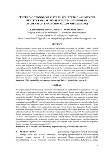
A:8J. Lu et al.(a) Placement without filler insertion.(b) Placement with filler insertion.(c) Placement with filler insertion (removed after placement finishes).Fig. 3: The distribution of standard cells and fillers at the end of global placement.Macros, standard cells and fillers are shown by black rectangles, red dots and bluedots, respectively. The total wirelength is shorter as fillers populate up whitespacethus squeeze cells to be placed closer. The placement is conducted on the ISPD05ADAPTEC1 benchmark using Nesterov’s method.quantity below the original DC level become negatively charged. Meanwhile, the overfilled regions remain positively charged but with reduced electric quantity (DC is deducted from the original quantity). Cells at positively charged (i.e. highly over-filled)regions are attracted to the negatively charged regions, where the positive and negative charges neutralize with each other. Meanwhile, cells at negatively charged regionswill mostly keep still. In the end, the system reaches the electrostatic equilibrium statewith zero charge density over the entire placement region, while the total potentialenergy is reduced to zero. As a result, we model the placement density penalty andgradient using the system potential energy and electric field, respectively.3.2. Density Penalty and Gradient FormulationThe total potential energy equals the sum of potential energy over all the chargedelements of a new set V ′ , which includes not only movable and fixed nodes from V , butalso newly added fillers and dark nodes as discussed below.Filler insertion: Let Am denote the total area of all the movable nodes, while Awsdenotes the total area of white space. The target of even density distribution will overlymspread the cells thus increase the wirelength, if we have the target density ρt AAws.Similar to [Adya et al. 2003; Chan et al. 2006], we add fillers into the system, all ofwhich are equally sized (rectangles), movable and disconnected (with zero pins). LetVf c denote the set of filler cells. The total area of filler cells is denoted as Af c anddefined as below.Af c ρt Aws Am .(13)We illustrate the effect of filler insertion in Figure 3. The additional density force dueto filler insertion will squeeze the cells to be placed closer to their connected neighborswith density constraint still satisfied. The size of each filler i is denoted as Ai , which isdetermined based on the area distribution of the movable cells. Specifically, we set thefiller size to be the average size of the mid 80% movable cells. The remaining top andbottom 10% largest and smallest cells are considered as noise factors and filtered out.All the fillers are removed from the final solution of global placement.Dark node insertion: As a generalized approach, our method could handle any irregularly shaped placement region without loss on quality or efficiency. Suppose that theentire placement instance comprises a set of rectangular regions for cell placement.We impose a uniform grid R to cover all the placement regions. The total space withinACM Transactions on Embedded Computing Systems, Vol. V, No. N, Article A, Publication date: January YYYY.
ePlace: Electrostatics based Placement using Fast Fourier Transform and Nesterov’s MethodA:9(a) Placement without macro density scal-(b) Density distribution without macro(c) Placement with macro density scaleding.density scaling.by the target density ρt .Fig. 4: Without macro area scaling, the bin density at the macro blocks becomes higherthan the target density ρt . As a result, the density force pushes the cells away frommacros, inducing under-filled whitespace around macros and wirelength overhead.R but not belonging to any placement region will be decomposed into a set of rectangles, each is modeled as a dark node, which is processed in the same way as that of afixed object in the problem instance. Let Vd denote the set of all the dark nodes andAd denote the total area of all the dark nodes. Movable nodes will be stopped by therepelling force from the dark nodes when they are approaching the boundaries of anyplacement regions.Density scaling: After the insertion of filler cells, we have the target density ρt Am Af cAws . The area Ai of each fixed or dark node i must be scaled by the target density ρt ,in order to maintain a globally equalized density distribution. Otherwise, the densityforce becomes higher than that of cells and fillers and repels cells away, while thewhitespace around the fixed nodes is emptied with wirelength overhead induced asFigure 4 shows. Notice that our density scaling method will not introduce legalizationissue. The electric quantity of each fixed or movable large macro is scaled down to thetarget placement density. Regions filled by small standard cells or covered by largemacros will have the same charge density, there is no additional density force to dragcells away from macros. Without density scaling, it is impossible to achieve even chargedensity distribution over the entire domain.Potential energy computation: Let V ′ Vm Vf Vf c Vd denote the set of allthe elements in the system. For each node i V ′ , let ρi , ξ i and ψi denote the electricdensity, field and potential at the point where the node i locates. Given a placementsolution v for both movable cells Vm and filler cells Vf c , the total potential energy N isdefined in Eq. (14)1 X1 XN (v) Ni qi ψi .(14)22′′i Vi VAs the system energy equals the sum of mutual energy of all the pairs of charges, wehave a factor of 21 for the energy of each single charge. We cast the numerous griddensity constraints into a single energy constraint of zero system energy (N (v) 0).Our density penalty is different from that of all the previous formulations [Chan et al.2006; Chen et al. 2008; Kahng and Wang 2006] where it consists of a complete electrostatic system model with all the according physics laws strictly
becomes sufficiently small. State-of-the-art works include Capo [Roy et al. 2006], Dragon [Taghavi et al. 2005] and Fengshui [Agnihorti et al. 2005]. However, improper partitioning at early stages could induce unrecoverable quality loss to the final solu-tion. Quadratic approaches approximate the net length using a quadratic function,