Transcription
PhysicsChapter SixELECTROMAGNETICINDUCTION6.1 INTRODUCTION204Electricity and magnetism were considered separate and unrelatedphenomena for a long time. In the early decades of the nineteenth century,experiments on electric current by Oersted, Ampere and a few othersestablished the fact that electricity and magnetism are inter-related. Theyfound that moving electric charges produce magnetic fields. For example,an electric current deflects a magnetic compass needle placed in its vicinity.This naturally raises the questions like: Is the converse effect possible?Can moving magnets produce electric currents? Does the nature permitsuch a relation between electricity and magnetism? The answer isresounding yes! The experiments of Michael Faraday in England andJoseph Henry in USA, conducted around 1830, demonstratedconclusively that electric currents were induced in closed coils whensubjected to changing magnetic fields. In this chapter, we will study thephenomena associated with changing magnetic fields and understandthe underlying principles. The phenomenon in which electric current isgenerated by varying magnetic fields is appropriately calledelectromagnetic induction.When Faraday first made public his discovery that relative motionbetween a bar magnet and a wire loop produced a small current in thelatter, he was asked, “What is the use of it?” His reply was: “What is theuse of a new born baby?” The phenomenon of electromagnetic induction2022-23
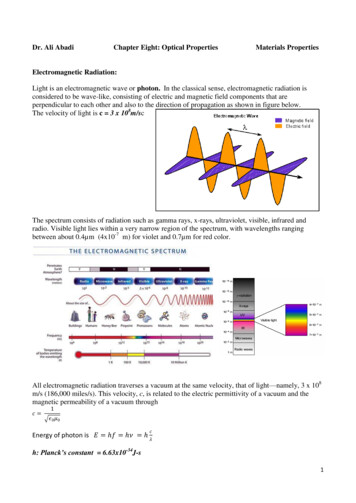
ElectromagneticInductionis not merely of theoretical or academic interest but alsoof practical utility. Imagine a world where there is noelectricity – no electric lights, no trains, no telephones andno personal computers. The pioneering experiments ofFaraday and Henry have led directly to the developmentof modern day generators and transformers. Today’scivilisation owes its progress to a great extent to thediscovery of electromagnetic induction.OFFARADAYANDThe discovery and understanding of electromagneticinduction are based on a long series of experiments carriedout by Faraday and Henry. We shall now describe someof these experiments.Experiment 6.1Figure 6.1 shows a coil C1* connected to a galvanometerG. When the North-pole of a bar magnet is pushedtowards the coil, the pointer in the galvanometer deflects,indicating the presence of electric current in the coil. Thedeflection lasts as long as the bar magnet is in motion.The galvanometer does not show any deflection when themagnet is held stationary. When the magnet is pulledaway from the coil, the galvanometer shows deflection inthe opposite direction, which indicates reversal of thecurrent’s direction. Moreover, when the South-pole ofthe bar magnet is moved towards or away from thecoil, the deflections in the galvanometer are oppositeto that observed with the North-pole for similarmovements. Further, the deflection (and hence current)is found to be larger when the magnet is pushedtowards or pulled away from the coil faster. Instead,when the bar magnet is held fixed and the coil C1 ismoved towards or away from the magnet, the sameeffects are observed. It shows that it is the relativemotion between the magnet and the coil that isresponsible for generation (induction) of electriccurrent in the coil.Experiment 6.2In Fig. 6.2 the bar magnet is replaced by a second coilC2 connected to a battery. The steady current in thecoil C2 produces a steady magnetic field. As coil C2 isJosheph Henry [1797 –1878] American experimentalphysicist, professor atPrinceton University and firstdirector of the SmithsonianInstitution. He made importantimprovements in electromagnets by winding coils ofinsulated wire around ironpole pieces and invented anelectromagnetic motor and anew, efficient telegraph. Hediscoverd self-induction andinvestigated how currents inone circuit induce currents inanother.FIGURE 6.1 When the bar magnet ispushed towards the coil, the pointer inthe galvanometer G deflects.* Wherever the term ‘coil’ or ‘loop’ is used, it is assumed that they are made up ofconducting material and are prepared using wires which are coated with insulatingmaterial.2022-23JOSEPH HENRY (1797 – 1878)6.2 THE EXPERIMENTSHENRY205
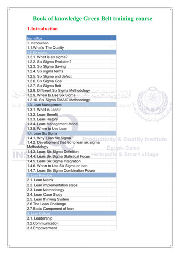
Physicsmoved towards the coil C1, the galvanometer shows adeflection. This indicates that electric current is induced incoil C1. When C2 is moved away, the galvanometer shows adeflection again, but this time in the opposite direction. Thedeflection lasts as long as coil C2 is in motion. When the coilC2 is held fixed and C1 is moved, the same effects are observed.Again, it is the relative motion between the coils that inducesthe electric current.Experiment 6.3FIGURE 6.2 Current isinduced in coil C1 due to motionof the current carrying coil C2.The above two experiments involved relative motion betweena magnet and a coil and between two coils, respectively.Through another experiment, Faraday showed that thisrelative motion is not an absolute requirement. Figure 6.3shows two coils C1 and C2 held stationary. Coil C1 is connectedto galvanometer G while the second coil C2 is connected to abattery through a tapping key K.FIGURE 6.3 Experimental set-up for Experiment 6.3.It is observed that the galvanometer shows a momentary deflectionwhen the tapping key K is pressed. The pointer in the galvanometer returnsto zero immediately. If the key is held pressed continuously, there is nodeflection in the galvanometer. When the key is released, a momentorydeflection is observed again, but in the opposite direction. It is also observedthat the deflection increases dramatically when an iron rod is insertedinto the coils along their axis.6.3 MAGNETIC FLUX206Faraday’s great insight lay in discovering a simple mathematical relationto explain the series of experiments he carried out on electromagneticinduction. However, before we state and appreciate his laws, we must getfamiliar with the notion of magnetic flux, Φ B. Magnetic flux is defined inthe same way as electric flux is defined in Chapter 1. Magnetic flux through2022-23
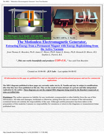
ElectromagneticInductiona plane of area A placed in a uniform magnetic field B (Fig. 6.4) canbe written asΦ B B . A BA cos θ(6.1)where θ is angle between B and A. The notion of the area as a vectorhas been discussed earlier in Chapter 1. Equation (6.1) can beextended to curved surfaces and nonuniform fields.If the magnetic field has different magnitudes and directions atvarious parts of a surface as shown in Fig. 6.5, then the magneticflux through the surface is given byΦ B . dA B . dA . B1122 Bi . dA i(6.2)allwhere ‘all’ stands for summation over all the area elements dAicomprising the surface and Bi is the magnetic field at the area elementdAi. The SI unit of magnetic flux is weber (Wb) or tesla metersquared (T m2). Magnetic flux is a scalar quantity.6.4 FARADAY’S LAWOFFIGURE 6.4 A plane ofsurface area A placed in auniform magnetic field B.INDUCTIONFrom the experimental observations, Faraday arrived at aconclusion that an emf is induced in a coil when magnetic fluxthrough the coil changes with time. Experimental observationsdiscussed in Section 6.2 can be explained using this concept.The motion of a magnet towards or away from coil C1 inExperiment 6.1 and moving a current-carrying coil C2 towardsor away from coil C1 in Experiment 6.2, change the magneticflux associated with coil C1. The change in magnetic flux inducesemf in coil C1. It was this induced emf which caused electricFIGURE 6.5 Magnetic field Bicurrent to flow in coil C1 and through the galvanometer. Aat the i th area element. dAiplausible explanation for the observations of Experiment 6.3 isrepresentsarea vector of theas follows: When the tapping key K is pressed, the current ini th area element.coil C2 (and the resulting magnetic field) rises from zero to amaximum value in a short time. Consequently, the magneticflux through the neighbouring coil C1 also increases. It is the change inmagnetic flux through coil C1 that produces an induced emf in coil C1.When the key is held pressed, current in coil C2 is constant. Therefore,there is no change in the magnetic flux through coil C1 and the current incoil C1 drops to zero. When the key is released, the current in C2 and theresulting magnetic field decreases from the maximum value to zero in ashort time. This results in a decrease in magnetic flux through coil C1and hence again induces an electric current in coil C1*. The commonpoint in all these observations is that the time rate of change of magneticflux through a circuit induces emf in it. Faraday stated experimentalobservations in the form of a law called Faraday’s law of electromagneticinduction. The law is stated below.* Note that sensitive electrical instruments in the vicinity of an electromagnetcan be damaged due to the induced emfs (and the resulting currents) when theelectromagnet is turned on or off.2022-23207
PhysicsThe magnitude of the induced emf in a circuit is equalto the time rate of change of magnetic flux through thecircuit.Mathematically, the induced emf is given byMICHAEL FARADAY (1791–1867)ε –Michael Faraday [1791–1867]Faraday madenumerous contributions toscience, viz., the discoveryofelectromagneticinduction, the laws ofelectrolysis, benzene, andthe fact that the plane ofpolarisation is rotated in anelectric field. He is alsocredited with the inventionof the electric motor, theelectric generator and thetransformer. He is widelyregarded as the greatestexperimental scientist ofthe nineteenth century.dΦBdt(6.3)The negative sign indicates the direction of ε and hencethe direction of current in a closed loop. This will bediscussed in detail in the next section.In the case of a closely wound coil of N turns, changeof flux associated with each turn, is the same. Therefore,the expression for the total induced emf is given byε –NdΦBdt(6.4)The induced emf can be increased by increasing thenumber of turns N of a closed coil.From Eqs. (6.1) and (6.2), we see that the flux can bevaried by changing any one or more of the terms B, A andθ. In Experiments 6.1 and 6.2 in Section 6.2, the flux ischanged by varying B. The flux can also be altered bychanging the shape of a coil (that is, by shrinking it orstretching it) in a magnetic field, or rotating a coil in amagnetic field such that the angle θ between B and Achanges. In these cases too, an emf is induced in therespective coils.208EXAMPLE 6.2EXAMPLE 6.1Example 6.1 Consider Experiment 6.2. (a) What would you do to obtaina large deflection of the galvanometer? (b) How would you demonstratethe presence of an induced current in the absence of a galvanometer?Solution(a) To obtain a large deflection, one or more of the following steps canbe taken: (i) Use a rod made of soft iron inside the coil C2, (ii) Connectthe coil to a powerful battery, and (iii) Move the arrangement rapidlytowards the test coil C1.(b) Replace the galvanometer by a small bulb, the kind one finds in asmall torch light. The relative motion between the two coils will causethe bulb to glow and thus demonstrate the presence of an inducedcurrent.In experimental physics one must learn to innovate. Michael Faradaywho is ranked as one of the best experimentalists ever, was legendaryfor his innovative skills.Example 6.2 A square loop of side 10 cm and resistance 0.5 Ω isplaced vertically in the east-west plane. A uniform magnetic field of0.10 T is set up across the plane in the north-east direction. Themagnetic field is decreased to zero in 0.70 s at a steady rate. Determinethe magnitudes of induced emf and current during this time-interval.2022-23
ElectromagneticInductionSolution The angle θ made by the area vector of the coil with themagnetic field is 45 . From Eq. (6.1), the initial magnetic flux isΦ BA cos θ 0.1 10 –2Wb2Final flux, Φmin 0The change in flux is brought about in 0.70 s. From Eq. (6.3), themagnitude of the induced emf is given byε ΦB t(Φ – 0 ) t 10 –3 1.0 mV2 0.7And the magnitude of the current is EXAMPLE 6.2ε10 –3 V 2 mAR0.5ΩNote that the earth’s magnetic field also produces a flux through theloop. But it is a steady field (which does not change within the timespan of the experiment) and hence does not induce any emf.I Example 6.3A circular coil of radius 10 cm, 500 turns and resistance 2 Ω is placedwith its plane perpendicular to the horizontal component of the earth’smagnetic field. It is rotated about its vertical diameter through 180 in 0.25 s. Estimate the magnitudes of the emf and current induced inthe coil. Horizontal component of the earth’s magnetic field at theplace is 3.0 10–5 T.SolutionInitial flux through the coil,ΦB (initial) BA cos θ 3.0 10–5 (π 10–2) cos 0 3π 10–7 WbFinal flux after the rotation,ΦB (final) 3.0 10–5 (π 10–2) cos 180 –3π 10–7 WbTherefore, estimated value of the induced emf is,ε N Φ t 500 (6π 10–7)/0.25I ε/R 1.9 10–3 ANote that the magnitudes of ε and I are the estimated values. Theirinstantaneous values are different and depend upon the speed ofrotation at the particular instant.2022-23EXAMPLE 6.3 3.8 10–3 V209
Physics6.5 LENZ’S LAWANDCONSERVATIONOFENERGYIn 1834, German physicist Heinrich Friedrich Lenz (1804-1865) deduceda rule, known as Lenz’s law which gives the polarity of the induced emfin a clear and concise fashion. The statement of the law is:The polarity of induced emf is such that it tends to produce a currentwhich opposes the change in magnetic flux that produced it.The negative sign shown in Eq. (6.3) represents this effect. We canunderstand Lenz’s law by examining Experiment 6.1 in Section 6.2.1. InFig. 6.1, we see that the North-pole of a bar magnet is being pushedtowards the closed coil. As the North-pole of the bar magnet moves towardsthe coil, the magnetic flux through the coil increases. Hence current isinduced in the coil in such a direction that it opposes the increase in flux.This is possible only if the current in the coil is in a counter-clockwisedirection with respect to an observer situated on the side of the magnet.Note that magnetic moment associated with this current has North polaritytowards the North-pole of the approaching magnet. Similarly, if the Northpole of the magnet is being withdrawn from the coil, the magnetic fluxthrough the coil will decrease. To counter this decrease in magnetic flux,the induced current in the coil flows in clockwise direction and its Southpole faces the receding North-pole of the bar magnet. This would result inan attractive force which opposes the motion of the magnet and thecorresponding decrease in flux.What will happen if an open circuit is used in place of the closed loopin the above example? In this case too, an emf is induced across the openends of the circuit. The direction of the induced emf can be foundusing Lenz’s law. Consider Figs. 6.6 (a) and (b). They provide an easierway to understand the direction of induced currents. Note that thedirection shown byFIGURE 6.6Illustration ofLenz’s law.210andindicate the directions of the inducedcurrents.A little reflection on this matter should convince us on thecorrectness of Lenz’s law. Suppose that the induced current was inthe direction opposite to the one depicted in Fig. 6.6(a). In that case,the South-pole due to the induced current will face the approachingNorth-pole of the magnet. The bar magnet will then be attractedtowards the coil at an ever increasing acceleration. A gentle push onthe magnet will initiate the process and its velocity and kinetic energywill continuously increase without expending any energy. If this canhappen, one could construct a perpetual-motion machine by asuitable arrangement. This violates the law of conservation of energyand hence can not happen.Now consider the correct case shown in Fig. 6.6(a). In this situation,the bar magnet experiences a repulsive force due to the inducedcurrent. Therefore, a person has to do work in moving the magnet.Where does the energy spent by the person go? This energy isdissipated by Joule heating produced by the induced current.2022-23
ElectromagneticInductionExample 6.4Figure 6.7 shows planar loops of different shapes moving out of orinto a region of a magnetic field which is directed normal to the planeof the loop away from the reader. Determine the direction of inducedcurrent in each loop using Lenz’s law.FIGURE 6.7Solution(i) The magnetic flux through the rectangular loop abcd increases,due to the motion of the loop into the region of magnetic field, Theinduced current must flow along the path bcdab so that it opposesthe increasing flux.(ii) Due to the outward motion, magnetic flux through the triangularloop abc decreases due to which the induced current flows alongbacb, so as to oppose the change in flux.(iii) As the magnetic flux decreases due to motion of the irregularshaped loop abcd out of the region of magnetic field, the inducedcurrent flows along cdabc, so as to oppose change in flux.Note that there are no induced current as long as the loops arecompletely inside or outside the region of the magnetic field.EXAMPLE 6.4Example 6.5(a) A closed loop is held stationary in the magnetic field between thenorth and south poles of two permanent magnets held fixed. Canwe hope to generate current in the loop by using very strongmagnets?(b) A closed loop moves normal to the constant electric field betweenthe plates of a large capacitor. Is a current induced in the loop(i) when it is wholly inside the region between the capacitor plates(ii) when it is partially outside the plates of the capacitor? Theelectric field is normal to the plane of the loop.(c) A rectangular loop and a circular loop are moving out of a uniformmagnetic field region (Fig. 6.8) to a field-free region with a constantvelocity v. In which loop do you expect the induced emf to beconstant during the passage out of the field region? The field isnormal to the loops.EXAMPLE 6.52022-23211
PhysicsFIGURE 6.8(d) Predict the polarity of the capacitor in the situation described byFig. 6.9.EXAMPLE 6.5FIGURE 6.9Solution(a) No. However strong the magnet may be, current can be inducedonly by changing the magnetic flux through the loop.(b) No current is induced in either case. Current can not be inducedby changing the electric flux.(c) The induced emf is expected to be constant only in the case of therectangular loop. In the case of circular loop, the rate of change ofarea of the loop during its passage out of the field region is notconstant, hence induced emf will vary accordingly.(d) The polarity of plate ‘A’ will be positive with respect to plate ‘B’ inthe capacitor.6.6 MOTIONAL ELECTROMOTIVE FORCELet us consider a straight conductor moving in a uniform and timeindependent magnetic field. Figure 6.10 shows a rectangular conductorPQRS in which the conductor PQ is free to move. The rod PQ is movedtowards the left with a constant velocity v asshown in the figure. Assume that there is noloss of energy due to friction. PQRS forms aclosed circuit enclosing an area that changesas PQ moves. It is placed in a uniform magneticfield B which is perpendicular to the plane ofthis system. If the length RQ x and RS l, themagnetic flux ΦB enclosed by the loop PQRSwill beΦB BlxSince x is changing with time, the rate of changeof flux ΦB will induce an emf given by:FIGURE 6.10 The arm PQ is moved to the leftside, thus decreasing the area of therectangular loop. This movementinduces a current I as shown.2122022-23ε – dΦBd –(Blx )dtdt – Bldx Blvdt(6.5)
ElectromagneticInductionwhere we have used dx/dt –v which is the speed of the conductor PQ.The induced emf Blv is called motional emf. Thus, we are able to produceinduced emf by moving a conductor instead of varying the magnetic field,that is, by changing the magnetic flux enclosed by the circuit.It is also possible to explain the motional emf expression in Eq. (6.5)by invoking the Lorentz force acting on the free charge carriers of conductorPQ. Consider any arbitrary charge q in the conductor PQ. When the rodmoves with speed v, the charge will also be moving with speed v in themagnetic field B. The Lorentz force on this charge is qvB in magnitude,and its direction is towards Q. All charges experience the same force, inmagnitude and direction, irrespective of their position in the rod PQ.The work done in moving the charge from P to Q is,W qvBlSince emf is the work done per unit charge,ε Wq BlvThis equation gives emf induced across the rod PQ and is identicalto Eq. (6.5). We stress that our presentation is not wholly rigorous. Butit does help us to understand the basis of Faraday’s law whenthe conductor is moving in a uniform and time-independentmagnetic field.On the other hand, it is not obvious how an emf is induced when aconductor is stationary and the magnetic field is changing – a fact whichFaraday verified by numerous experiments. In the case of a stationaryconductor, the force on its charges is given byF q (E v B) qE(6.6)since v 0. Thus, any force on the charge must arise from the electricfield term E alone. Therefore, to explain the existence of induced emf orinduced current, we must assume that a time-varying magnetic fieldgenerates an electric field. However, we hasten to add that electric fieldsproduced by static electric charges have properties different from thoseproduced by time-varying magnetic fields. In Chapter 4, we learnt thatcharges in motion (current) can exert force/torque on a stationary magnet.Conversely, a bar magnet in motion (or more generally, a changingmagnetic field) can exert a force on the stationary charge. This is thefundamental significance of the Faraday’s discovery. Electricity andmagnetism are related.2022-23EXAMPLE 6.6Example 6.6 A metallic rod of 1 m length is rotated with a frequencyof 50 rev/s, with one end hinged at the centre and the other end at thecircumference of a circular metallic ring of radius 1 m, about an axispassing through the centre and perpendicular to the plane of the ring(Fig. 6.11). A constant and uniform magnetic field of 1 T parallel to theaxis is present everywhere. What is the emf between the centre andthe metallic ring?213
PhysicsFIGURE 6.11SolutionMethod IAs the rod is rotated, free electrons in the rod move towards the outerend due to Lorentz force and get distributed over the ring. Thus, theresulting separation of charges produces an emf across the ends ofthe rod. At a certain value of emf, there is no more flow of electronsand a steady state is reached. Using Eq. (6.5), the magnitude of theemf generated across a length dr of the rod as it moves at right anglesto the magnetic field is given bydε Bv dr . Hence,RR00ε dε Bv dr B ωr dr B ωR 22Note that we have used v ω r. This gives1 1.0 2π 50 (12 )2 157 Vε Method IITo calculate the emf, we can imagine a closed loop OPQ in whichpoint O and P are connected with a resistor R and OQ is the rotatingrod. The potential difference across the resistor is then equal to theinduced emf and equals B (rate of change of area of loop). If θ is theangle between the rod and the radius of the circle at P at time t, thearea of the sector OPQ is given byθ1 2R θ2π 2where R is the radius of the circle. Hence, the induced emf is214EXAMPLE 6.6π R2 ε B d 1 2 1Bω R 22 dθRθBR dt 22dt2dθ ω 2 πν ]dtThis expression is identical to the expression obtained by Method Iand we get the same value of ε.[Note:2022-23
ElectromagneticInductionExample 6.7A wheel with 10 metallic spokes each 0.5 m long is rotated with aspeed of 120 rev/min in a plane normal to the horizontal componentof earth’s magnetic field HE at a place. If HE 0.4 G at the place, whatis the induced emf between the axle and the rim of the wheel? Notethat 1 G 10–4 T.SolutionInduced emf (1/2) ω B R2 6.28 10–5 VThe number of spokes is immaterial because the emf’s across thespokes are in parallel.EXAMPLE 6.7 (1/2) 4π 0.4 10–4 (0.5)26.7 ENERGY CONSIDERATION: A QUANTITATIVE STUDYIn Section 6.5, we discussed qualitatively that Lenz’s law is consistent withthe law of conservation of energy. Now we shall explore this aspect furtherwith a concrete example.Let r be the resistance of movable arm PQ of the rectangular conductorshown in Fig. 6.10. We assume that the remaining arms QR, RS and SPhave negligible resistances compared to r. Thus, the overall resistance ofthe rectangular loop is r and this does not change as PQ is moved. Thecurrent I in the loop is,εI rBl v (6.7)rOn account of the presence of the magnetic field, there will be a forceon the arm PQ. This force I (l B), is directed outwards in the directionopposite to the velocity of the rod. The magnitude of this force is,B 2l 2vrwhere we have used Eq. (6.7). Note that this force arises due to drift velocityof charges (responsible for current) along the rod and the consequentLorentz force acting on them.Alternatively, the arm PQ is being pushed with a constant speed v,the power required to do this is,P FvF I lB B 2l 2v 2(6.8)rThe agent that does this work is mechanical. Where does thismechanical energy go? The answer is: it is dissipated as Joule heat, andis given by 2B 2l 2v 2 Blv r rrwhich is identical to Eq. (6.8).PJ I 2r 2152022-23
PhysicsThus, mechanical energy which was needed to move the arm PQ isconverted into electrical energy (the induced emf) and then to thermal energy.There is an interesting relationship between the charge flow throughthe circuit and the change in the magnetic flux. From Faraday’s law, wehave learnt that the magnitude of the induced emf is, ΦB tHowever,ε ε Ir Qr tThus, Q ΦBrExample 6.8 Refer to Fig. 6.12(a). The arm PQ of the rectangularconductor is moved from x 0, outwards. The uniform magnetic field isperpendicular to the plane and extends from x 0 to x b and is zerofor x b. Only the arm PQ possesses substantial resistance r. Considerthe situation when the arm PQ is pulled outwards from x 0 to x 2b,and is then moved back to x 0 with constant speed v. Obtain expressionsfor the flux, the induced emf, the force necessary to pull the arm and thepower dissipated as Joule heat. Sketch the variation of these quantitieswith distance.(a)FIGURE 6.12Solution Let us first consider the forward motion from x 0 to x 2bThe flux ΦB linked with the circuit SPQR is216EXAMPLE 6.8ΦB B l x Bl b0 x bb x 2bThe induced emf is,dΦε Bdt Bl v0 x b 0b x 2b2022-23
ElectromagneticInductionWhen the induced emf is non-zero, the current I is (in magnitude)Bl vrI (b)FIGURE 6.12The force required to keep the arm PQ in constant motion is I l B. Itsdirection is to the left. In magnitudeB 2l 2v0 x br 0b x 2bThe Joule heating loss isF PJ I 2r0 x bb x 2bOne obtains similar expressions for the inward motion from x 2b tox 0. One can appreciate the whole process by examining the sketchof various quantities displayed in Fig. 6.12(b).2022-23EXAMPLE 6.8B 2l 2v 2r 0 217
Physics6.8 EDDY CURRENTSSo far we have studied the electric currents induced in well defined pathsin conductors like circular loops. Even when bulk pieces of conductorsare subjected to changing magnetic flux, induced currentsare produced in them. However, their flow patterns resembleswirling eddies in water. This effect was discovered by physicistFoucault (1819-1868) and these currents are called eddycurrents.Consider the apparatus shown in Fig. 6.13. A copper plateis allowed to swing like a simple pendulum between the polepieces of a strong magnet. It is found that the motion is dampedand in a little while the plate comes to a halt in the magneticfield. We can explain this phenomenon on the basis ofelectromagnetic induction. Magnetic flux associated with theplate keeps on changing as the plate moves in and out of theregion between magnetic poles. The flux change induces eddycurrents in the plate. Directions of eddy currents are oppositewhen the plate swings into the region between the poles andwhen it swings out of the region.If rectangular slots are made in the copper plate as shownFIGURE 6.13 Eddy currents are in Fig. 6.14, area available to the flow of eddy currents is less.Thus, the pendulum plate with holes or slots reducesgenerated in the copper plate,while enteringelectromagnetic damping and the plate swings more freely.and leaving the region ofNote that magnetic moments of the induced currents (whichmagnetic field.oppose the motion) depend upon the area enclosed by thecurrents (recall equation m I A in Chapter 4).This fact is helpful in reducing eddy currents in the metalliccores of transformers, electric motors and other such devices inwhich a coil is to be wound over metallic core. Eddy currents areundesirable since they heat up the core and dissipate electricalenergy in the form of heat. Eddy currents are minimised by usinglaminations of metal to make a metal core. The laminations areseparated by an insulating material like lacquer. The plane of thelaminations must be arranged parallel to the magnetic field, sothat they cut across the eddy current paths. This arrangementreduces the strength of the eddy currents. Since the dissipationof electrical energy into heat depends on the square of the strengthof electric current, heat loss is substantially reduced.Eddy currents are used to advantage in certain applications like:FIGURE 6.14 Cutting slotsin the copper plate reducesthe effect of eddy currents.218(i) Magnetic braking in trains: Strong electromagnets are situatedabove the rails in some electrically powered trains. When theelectromagnets are activated, the eddy currents induced in therails oppose the motion of the train. As there are no mechanicallinkages, the braking effect is smooth.(ii) Electromagnetic damping: Certain galvanometers have a fixedcore made of nonmagnetic metallic material. When the coiloscillates, the eddy currents generated in the core oppose themotion and bring the coil to rest quickly.2022-23
ElectromagneticInduction(iii) Induction furnace: Induction furnace can be used to produce hight
Electromagnetic Induction 207 a plane of area A placed in a uniform magnetic field B (Fig. 6.4) can be written as Φ B B . A BA cos θ (6.1) where θ is angle between B and A. The notion of the area as a vector has been discussed earlier in Chapter 1.