Transcription
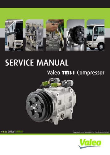
LCJNG.JIALJ1P37QMB(3B3)4- STROKE 50ccSERVICE MANUAL
CONTENTSCONTENTSSPECIFICATION/TIGHTEN TORQUE VALVE1MAINTENANCE INFORMATION2LUBRICATION SYSTEM3ELECTRONICALLY CONTROLLED CARBURETOR SYSTEM4REMOVAL ENGINE5CYLINDER HEAD & VALVE6CYLINDER & PISTON7V BELT DRIVING SYSTEM / KICK START SYSTEM8FINAL DRIVING SYSTEM9ACG10CRNKCASE & CRANKSHAFT11STARTING CLUTCH12
1. SPECIFICATION / TIGHTEN TORQUE VALUESLONO.IIASPECIFICATIONS . 1-1TORQUE VALUES (ENGINE). 1-2SPECIFICATIONSLONGJIAMODEL3B3Type4-STROKE ENGINEIgnitionTransistorized coilignitionInstallation andarrangementFuel UsedVertical, below center,incline 80 Unleaded (92/95)4-stroke/forced aircooledStarting SystemElectrical & Kick starterCylinderENGINECycle/CoolingBore37.0 mmStroke46.0 mmNumber/ArrangementSingle CylinderDecelerationequipmentMAKERPrimary ReductionSecondaryReductionBeltGEARClutchAuto centrifugal clutchTransmissionC.V.T25km/h2.3 kw/6500rpm45km/h3.0 kw/8000rpm25km/h3.5N.m /6000 rpm45km/h3.6N.m /7500 rpmMax. HPDisplacement49.46 ccCompression Ratio12 0.2 : 1Idle speed1900 100 rpmMax.TorqueSpark PlugCR6HSAStandard Torque Values for ReferenceTYPETIGHTEN TORQUETYPETIGHTEN TORQUE5mm bolt、nut6mm bolt、nut8mm bolt、nut10mm bolt、nut12mm bolt、nut4.5 6.0N.m3mm screw4mm screw5mm screw6mm screw、SH nut6mm bolt、nut0.5 0.8N.m8mm bolt、nut24 30N.m10mm bolt、nut35 45N.m8 12N.m18 25N.m30 40N.m50 60N.m1.0 1.5N.m3.5 5.N.m7 11N.m10 14N.m1-1
1. SPECIFICATION / TIGHTEN TORQUE VALUESL0.,.0 .HATORQUE VALUES (ENGINE)ITEMQ'TYTHREAD DIA TORQUE(mm)VALUE(N.m)REMARKSCylinder head bolts268 12Cylinder head left side cover bolts268 12Cylinder head nuts4612 16Apply oil to threadCylinder/cylinder head two-ends bolts467 11Tighten to crankcaseTappet adjust hole cap23013 17Camshaft sprocket bolt1820 25Right crank case cover bolts1068 12Pulse generator bolts255 7Valve adjustment fixing nuts257 11Spark plug11010 14Engine oil filter screen cap13013 17Engine oil drain plug boltGear oil draining plugGear oil filling boltOil pump flat screwLeft crankcase cover boltsCamshaft chain tensioner pivotCamshaft chain adjuster boltsCooling fan boltsCooling fan cover boltRR. brake shoe anchor fixing nutShroud A/BStart clutch lock nutFlywheel nutTransmission(Gear box) boltsMovable drive face nutDrive pulley nutA.C. generator flange boltStart motor boltsCrankcase boltsAir/C connect bracket boltsKick starter arm boltInlet pipe 666620 2610 1510 158 128 128 1210 148 127 1115 208 1270 8035 4520 2555 6535 458 128 128 128 128 128 12Exhaust pipe bolts267 11Apply oil to threadHex socket boltApply oil to threadThe torque values listed in above table are for more important tighten torque values. Pleasesee standard values for not listed in the table.1-2
e2. MAINTENANCE INFORMATIONLCNl:ii JIAPRECAUTIONS IN OPERATION . 2-1PERIODICAL MAINTENANCESCHEDULE . 2-2LUBRICATION SYSTEM . 2-3AIR CLEANER . 2-4VALVE CLEARANCE INSPECTION &ADJUSTMENT . 2-5CARBURETOR IDLING SPEEDADJUSTMENT .2-5IGNITION SYSTEM/SPARK PLUG .2-6CYLINDER COMPRESSIONPRESSURE .2-7DRIVING SYSTEM .2-7CRANKCASE BLOW-BY SYSTEM .2-8PRECAUTIONS IN OPERATIONSpecificationFuel Tank CapacityEngine OilTransmission Gear oil6.2Lcapacity800 c.c.change700 c.c.capacity140 c.c.change120 c.c.Clearance of throttle valve2 6 mmSpark plugIdling speedCR6HSA Gap: 0.6 0.7 mm1900 100 rpmCylinder compression pressure9.5 0.5 bar/550rpmValve clearance: IN/EX0.05 0.02 mm/0.10 0.02 mm45Km/h25Km/h"F"Mark in idling speedBefore TDC 13 /2000 rpmFull timing advancedBefore TDC 28 /8000 rpm"F"Mark in idling speedBefore TDC 15 /2000 rpmFull timing advancedBefore TDC 28 /6500 rpm2-1
2. MAINTENANCE INFORMATIONLCNl:.-IIAPERIODICAL MAINTENANCE 192021222324252627ItemInitial 300KM Air cleaner Fuel filter Oil filter Engine oil changeTire pressureBattery inspectionBrake & free play checkSteering handle checkCushion operation checkEvery screw tightening checkGear oil check for leaking Spark plug check or change Gear oil changeFrame lubricationExhaust pipe Ignition timing Emission check in Idling Throttle operation Engine bolt tightening CVT driving device (belt﹞ CVT driving device (roller)Lights/electrical equipment/mutli-metersMain/side stands & springsFuel pipesCam chain Valve clearance Crankcase blow-by over-flow pipeCode: I Inspection, cleaning, and adjustmentIICRIIIIIIIIRIIAII1 Month3 month6 monthEvery1000KM Every3000KM Every6000KMCCICReplacement for every 1000km1 yearEvery12000KMRRCIIIIIIIIRReplacement for every 5000kmLIIIIIICIIIIIIR ReplacementRIIIIAReplacement for every 1000kmC Cleaning (replaced if necessary)L LubricationHave your motorcycle checked, adjusted, and recorded maintenance data periodically by your LLL Authorized Dealer tomaintain the motorcycle at the optimum conditionThe above maintenance schedule is established by taking the monthly 1000 kilometers as a reference which ever comesfirst.Remarks:1. These marks “ ” in the schedule are emission control items. According to EEC regulations, these itemsmust be perform normally periodical maintenance following the use r manual instructions. They areprohibited to be adjusted or repaired by unauthorized people. Otherwise, LONGJIA is no responsible forthe charge.2. Clean or replace the air cleaner element more often when the motorcycle is operated on dusty roads or in theHeavily- polluted environment.3. Maintenance should be performed more often if the motorcycle is frequently operated in high speed and afterthe motorcycle has accumulated a higher mileage.4. Preventive maintenancea. Ignition system - Perform maintenance and check when continuous abnormal ignition, misfire, after-burn,overheating occur.b. Carbon deposit removal - Remove carbon deposits in cylinder head, piston heads, exhaust system when power isobvious lower than ever.c. Replace worn out pistons, cylinder head.2-2
2. MAINTENANCE INFORMATIONLUBRICATION SYSTEMEngine Oil CapacityCautionŸ The vehicle must be parked on a levelground when checking oil capacity.Ÿ Run the engine for 2-3 minutes thenstop, wait about 2-3 more minutesallowing engine oil to settle beforechecking the oil level.Remove dipstick to check the oil level. If oillevel is below the lower limit mark, add oil tothe specified upper limit mark.DipstickOil changeShut off the engine and remove dipstick.Remove the oil drain plug on the bottom-leftof crankcase to drain oil.After draining out oil, clean oil plug and itsgasket and reinstall. Replace the gasket if itis damaged.Torque value: 20 26 N.mCautionWarm up the engine. This will make the oilflow out easily.Add oil to the specified capacity.Oil Viscosity: SAE 15W-40, recommendedusing API GL-4Engine oil capacity:Disassembly: 800ccChange:700ccWhen checking for oil leak, run the engine atidle speed for a few minutes, then check oilcapacity with dipstick.Cleaning the oil strainerDrain oil from engine, remove the strainercover, spring and strainer.If there is an accumulation on the screen,wash it off with suitable solvent(recommended using compressed air).Check O-ring for damage, replace ifnecessary.Reinstall strainer, spring, O-ring and strainercover.Torque value: 13 17 N.mOil drain plugstrainer coveroil strainerspring2-3
2. MAINTENANCE INFORMATIONL.CINla.llAGear OilInspectionCheck gear oil if leaking.Park the motorcycle with main stand on flatlevel place.Turn off engine and remove the gear oildraining plug.Place a measurement cup under thedraining hole.Remove the oil drain plug and drain gear oilinto a measurement cup.Check gear oil if enough.ReplacementAt first, remove the gear oil refilling bolt, andthen remove the draining plug.Install the draining plug after drained oil out.Torque value: 10 15 N.mGear oil refilling boltCautionInspect if washer is in good condition.Replace it with new one if it was deformedor damaged.Fill out gear oil to specified quantity from theengine oil filling hole.Install the oil filling bolt.Torque value: 10 15 N.mTransmission oil capacity: 140 c.c.(120c.c. for change)Recommended: API GL-4 gear oil (SAE80W-90).Gear oil draining plugAIR CLEANERElementRemove frame body cover.Remove 6 screws from the air cleaner cover.Remove element of air cleaner (2 screws).Check the element if dirt or damaged.Replace it with new one if dirt or damaged.CautionŸ Air cleaner element contains a papermade filter so do not try to clean it.Ÿ Make sure that the air cleaner coverhad been installed properly afterinstallation.2-4Screws 6
LCNlli.llA2. MAINTENANCE INFORMATIONVALVE CLEARANCE ADJUSTMENTAir cleaner elementCautionChecks and adjustment must be performedwhen engine is cold (below 35 ).Remove luggage box and front center cover.Remove the left body cover & left side cover.Remove cylinder head cap.Remove the ignition timing check hole on thecooling fan cover.With “T” type wrench, turn crankshaft inclockwise motion so that mark (“T”) on thegenerator flywheel aligns with the mark onthe crankshaft, and camshaft is at TDCposition also as same as level of cylinderhead top-end. A single hole on camshaftsprocket is forward to up. (Piston is at TDCposition in the compression stroke.)CautionThe crankshaft can not be rotated incounter-clockwise to prevent from damageso that valve clearance can not bemeasured.VALVE CLEARANCE INSPECTIONAND ADJUSTMENTIgnition timing markClearanceCheck & adjust valve clearance with feelergauge.Valve clearance (IN/EX):0.05 0.02 mm/0.10 0.02 mmLoosen fixing nut and turn the adjustmentnut for adjustment.CautionIt has to make sure that valve-rocker arm isbe adjusted to standard level whenadjusting it, and re-check the valveclearance after tightened the fixing nut.CARBURETOR IDLE SPEEDADJUSTMENTCautionŸ Inspection & adjustment for idle speedhave to be performed after all otherparts in engine that neededadjustment have been adjusted.Ÿ Idle speed check and adjustmenthave to be done after engine is beingwarm up(around 10 minutes).Ignition coil cable2-5
2. MAINTENANCE INFORMATIONPark the motorcycle with main stand andwarn up engine.Open the carburetor cover from the luggage box.Turn the throttle valve stopper screw tospecified idle speed.Specified idle speed: 1900 100 rpmEmission adjustment in Idle speedWarm up the engine for around 10 minutesand then conduct this adjustment.1. Connect the tachometer onto engine.2. Adjust the idle speed adjustment screwand let engine runs in 1900 100 rpm.3. Insert the exhaust sampling muffler ofexhaust analyzer into the front section ofexhaust pipe. Adjust the air adjustmentscrew so that emission value in idle speedis within standard.4. Slightly accelerate the throttle valve andrelease it immediately. Repeat this for 2 3 times.5. Read engine RPM and value on theexhaust analyzer. Repeat step 2 to step 4procedures until measured value withinEuro 4 standard.Exhaust Emission: CO: 1000mg/kmTHC: 630mg/kmNOx: 170mg/kmLCINltii.llAThrottle valve stopper screwAir adjustment screwSPARK PLUGAppointed spark plug: CR6HSARemove luggage box.Remove center cover.Remove spark plug cap.Clean dirt around the spark plug hole.Remove spark plug.Measure spark plug gap.Spark plug gap: 0.6 0.7 mmCarefully bend ground electrode of the plugto adjust the gap if necessary.Screw the park plug into the plug hole withhands, then tighten the plug with a wrench toprevent from damaging the spark plug'sthread.Torque value: 10 14 N.mConnect spark plug cap.2-6Side electrode0.6 0.7mmCenter electrode
2. MAINTENANCE INFORMATIONCYLINDER COPMRESSION PRESSUREWarn up engine and then turnoff the engine.Remove the luggage box and the centerCover.Remove spark plug cap and spark plug.Install compression gauge.Full open the throttle valve, and rotate theengine by means of stepping thekick-starting lever.CautionRotate the engine until the reading in thegauge no more increasing.Usually, the highest pressure reading will beobtained in 4 7 seconds.Spark plug capCompression pressure: 9.5 0.5 bar.Check following items if the pressure is toolow:l Incorrect valve clearancel Valve leakingl Cylinder head leaking, piston, piston ringand cylinder worn outIf the pressure is too high, it means carbondeposits in combustion chamber or pistonhead.Gear teethDRIVING SYSTEMDRIVING BELTRemove left side cover.Remove mounting bolt located under aircleaner.Remove 9 bolts of the engine left crankcase.Remove the left crankcase cover.Check if the belt is crack or worn out.Replace the belt if necessary or in accordwith the periodical maintenance schedule toreplace it.Width limit: above 17.2 mmClutch padStart the motorcycle and gradually increasethrottle valve openness to check clutch padoperation.If the motorcycle moves with shaking, thencheck its clutch pad for wearing. Replace itif necessary.WidthClutch padClutch2-7
2. MAINTENANCE INFORMATIONCrankcase blow-by over-flow pipeReplacement for every 1000km1.Open the stopper2.Drain the oil3.Install the stopperRemove dipstick to check the oil level. If oillevel is below the lower limit mark, add oil tothe specified upper limit mark.2-8LONG-IIA
-08: 3. LUBRICATION SYSTEMLCNl:ii JIAOIL FLOW DIAGRAM . 3-1GENERAL INFORMATION . 3-2TROUBLESHOOTING . 3-2ENGINE OIL . 3-3CLEANING ENGINE OIL STRAINER .3-3OIL PUMP.3-4GEAR OIL .3-6OIL FLOW DIAGRAMValve rockerarmForcedly lubricationCamshaftScoop lubricationInner passageConnecting rodForcedlylubricationCrankshaftOil strainerOil pump3-1
3. LUBRICATION SYSTEMLCJNl:ii JIAGENERAL INFORMATIONThis chapter contains maintenance operations for the engine oil pump, engine oil andgear oil.Oil viscositySpecificationsEngine oil quantityDisassembly 800 c.c.Replacement 700 c.c.lOil viscositySAE 15W-40 or equivalentUse SAE 5W-40 whenoutside temperature isbelow 0 .Gear Oil quantity0Disassembly 140 c.c.Replacement 120 c.c.·20-100102030Oil viscosity of gear oil SAE 80W-90 (RecommendAPI GL-4)ItemsOil pumpInner rotor clearanceClearance between outerrotor and bodyClearance between rotorside and bodyTorque valueEngine oil drain plugEngine oil filter screen capGear oil drain boltGear oil filling boltOil pump fixing screwsStandardunit : mmLimit-0.12-0.120.05 0.100.2020 26N.m13 17N.m10 15N.m10 15N.m8 12N.mTROUBLESHOOTINGLow engine oil levellOil leakinglValve guide or seat worn outlPiston ring worn outLow Oil PressurelLow engine oil levellClogged in oil strainer, circuits or pipeslOil pump damage3-2Dirty oillNo oil change in periodicallCylinder head gasket damagelPiston ring worn out40C
LCJNGi.JIA3. LUBRICATION SYSTEMENGINE OILTurn off engine, and park the motorcycle inflat ground with main stand.Check oil level with oil dipstick after 3-5minutes.Do not rotate the dipstick into engine aschecking.If oil level is nearly low level, fill outrecommended oil to upper level.DipstickOil ReplacementCautionDrain oil as engine warmed up so thatmake sure oil can be drained smoothly andcompletely.Place an oil pan under the motorcycle, andremove oil strainer cap.Make sure if the aluminum washer of thedraining bolt is damaged. If so, replace itwith new one.Install the drain plug and tighten it.Torque value: 20 26 N.mOil drain plugCLEANING ENGINE OIL STRAINERRemove the oil strainer cap.Remove oil strainer and spring.Clean oil strainer (recommended usingcompressed air to clean dirty foreign).Check if the strainer and O-ring of the oilstrainer are broken. Replace with new one iffound.Install the oil strainer and spring.Install the oil strainer cap and tighten it.Torque value: 13 17 N.mFill out oil to the oil filler (Oil viscosity SAE15W-40)Use SAE 5W-40 when outside temperatureis below 0 .Engine oil quantity: Replacement 700 c.c.Oil strainer capoil strainerspring3-3
3. LUBRICATION SYSTEMOIL PUMPOil Pump RemovalRemove the alternator (refer to chapter12).Remove the engine right crankcase cover.Make sure that the pump axle can be rotatedfreely.Remove the oil pump driving gear nut.Remove the oil pump .Oil Pump InspectionCheck the clearance between oil pump bodyand outer rotor.Limit: below 0.12 mmCheck clearance between inner and outerrotors.Limit: below 0.12 mm3-4
- "" LCNl:ii JIA3. LUBRICATION SYSTEMCheck clearance between rotor side faceand pump body.Limit: below 2.0 mmOil Pump Re-assemblyInstall inner and outer rotors into the pumpbody.Align the indent on driving shaft with that ofinner rotor. Install the driving shaft.Install the oil pump cover and fixing pinproperly and then tighten screw. (1 screw)Oil pump bodyouter rotorDrive shaftinner rotorFixing pinOil pumpcoverOil Pump InstallationInstall according to the reverse procedure ofremoval.3-5
3. LUBRICATION SYSTEM0LONm:.JtAGEAR OILOil Level InspectionPark the motorcycle on flat ground with mainstand.Turn off engine and remove both gear oilfilling bolt and gear oil draining plug.Remove gear oil filling bolt and place ameasurement cup under the draining plug.Remove the oil draining plug and the pourgear oil into the measurement cup.Measure the gear oil quantity if withinstandard value.Add specified gear oil if the oil level too low.Standard quantity: 140 cc.Replacement: 120 cc.Gear Oil ReplacementRemove the gear oil filling bolt and itsdraining plug and then drain oil completely.Install the draining plug and tighten it. (Makesure if the plug washer is damaged. If so,replace it with new one.)Torque Value:10 15 N.mAdd new gear oil (120 c.c.) from the gear oilfilling hole and then install the gear oil fillinghole bolt after added oil. And then, tightenthe bolt.Torque Value: 10 15 N.m※Recommended to apply with SAE80W-90. (Recommend API GL-4)Start engine and run it for 2 3 minutes.Turn off engine and check if oil leaking.3-6Gear oil draining plug
- 4. ELECTRONICALLY CONTROLLED CARBURETOR SYSTEMLDNa.J LAECS illustration .4-1Precautions in operation . 4-2ECSGeneral Information . 4-3ILLUSTRATION(Oxygensensor)ECU(Bectronically controlledc.arbure·tor)t Dutyfactor solenoid(Al)valve )(catalyst )(Engine. peed sensor)4-1
4.ELECTRONICALLY CONTROLLED CARBURETOR SYSTEMGeneral InformationCautions Do not bend or twist throttle valve cable. Damaged cable will make unstable driveability. When disassembling fuel system parts, pay attention to O-ring position, replace with newone as re-assembly There is a drain screw in the float chamber for draining residual gasoline. Do not disassemble automatic by-starter and air cut-off valve arbitrarily.SpecificationItemMain jetSpecificationSpeed limited:45km/h86#Speed limited:25km/h86#Speed limited:30km/h86#Pilot Jet33#Needle Jet2.1 mmLevel in float chamber21.5 0.5 mmFloat needle1.6 mmMass of float7.2g 0.1 gIdle speed2000 100 rpmFuel quantity adjustment screw2Jet needle3r21Throttle handle free play2 6 mmTorque valueFuel valve tightening nut: 1.5 2.0 Kgf-mToolSpecial service toolsVacuum/air pressure pumpGeneral service toolsFuel level gauge4-21/2 1/2
LCINl'!S.JIA4. ELECTRONICALLY CONTROLLED CARBURETOR SYSTEMCARBURETOR REMOVALRemove the luggage box.Loosen the adjustment nut and fixing nut ofthrottle valve cable, and release the cablefrom carburetor.Remove fuel pipe, vacuum hose.Disconnect auto by-starter connector.Disconnect gulp valve connectors.Disconnect TPS controller connector.Release the clamp strip of air cleaner.Release the clamp strip of carburetor isolator.Take the carburetor out.VACUUM CHAMBERRemovalLoosen drain screw, and drain out residualfuel in float chamber.Remove screws (2 screws) of vacuumchamber cover and the cover.4-3
5. REMOVAL OF ENGINEMECHANISM DIAGRAM . 5-1OPERATIONAL PRECAUTIONS . 5-2MECHANISM DIAGRAM3.5 4.5kgf-m4.5 5.5kgf-m4.5 5.5kgf-m2.4 3.0kgf-mo,/ -- 114.5 5.5 kgf-m5-1
5. REMOVAL OF ENGINEOPERATIONAL PRECAUTIONSGeneral InformationEngine must be supported by a bracket or adjustable tool in height.The following parts can be serviced with the engine installed on the frame.1. Carburetor2. Driving disk, driving belt, clutch, and transporting disk3. Final reduction gear mechanismSpecificationSpecificationEngine Oil CapacityGear Oil CapacityDisassemble800 c.c.Replacement700 c.c.Disassemble140 c.c.Replacement120 c.c.Torque ValuesEngine suspension bolt (frame side)Engine suspension nut (engine side)Bolt of rear shock absorber upper connectionBolt of rear shock absorber lower connection5-245 55N. m45 55 N. m35 45 N. m24 30 N. m
6. CYLINDER HEAD / VALVELCi .JlACOMPONENT STRUCTURE .GENERAL INFORMATION .TROUBLESHOOTING.CYLINDER HEAD REMOVAL .CAMSHAFT REMOVAL .6-16-26-26-36-5CYLINDER HEAD DISASSEMBLY . 6-6CYLINDER HEAD INSPECTION . 6-7.CYLINDER HEAD REASSEMBLY . 6-8CYLINDER HEAD INSTALLATION. 6-9VALVE CLEARANCE ADJUSTMENT. 6-10COMPONENT STRUCTURE Prevention Modification Screw8 12 N.mUDI'13 17 N.m @7 11 N.mQ- - --rr.I1IIr' (I) '-10 12 N.m'.-," !-1 -/ '8 12 N.m12 16 N.m20 25 N.m8 12 N.m6-1
6. CYLINDER HEAD / VALVEGENERAL INFORMATIONŸŸThis chapter is contained maintenance and service for cylinder head, valve, andcamshaft as well as valve rocker arm.Cylinder head service cannot be carried out when engine is in frame.SpecificationCamshaftRockerarmunit: mmItemStandardLimitCompression pressure9.5 0.5barAt 550rpm-Intake25.54 25.7025.14Exhaust25.14 25.3024.74ID of valve rocker arm10.000 10.01510.10OD of valve rocker arm shaft9.972 9.9879.90Intake4.970 4.984.90Exhaust4.955 4.974.905.000 5.0125.030Intake0.03 0.070.08Exhaust0.08 0.120.1331.8 33.031Height of cam lobeOD of valve stemID of GuideValveClearance betweenvalve stem and guideFree length of valvespringTROUBLESHOOTINGCylinder head cover boltCamshaft sprocket boltBolt of timing chain auto-adjusterSpark plugCylinder head nutValve adjustment fixing nutsTOOLSSpecial service toolsValve reamer: 5.0mmValve guide driver: 5.0mmValve spring compressor6-28 12 N.m20 25 N.m8 12 N.m10 12 N.m12 16 N.m7 11 N.m
6. CYLINDER HEAD / VALVECYLINDER HEAD REMOVALRemove the engine from the vehicle(Refer to chapter 5).Remove the shroud of the engine.Remove the crankcase blow-by systemhose from the cylinder head.Remove the cylinder head cover 4 Cat nutand then remove the cylinder head cover.Cat nut 4Loosen the bolt of camshaft chain adjusterin a counter-clockwise motion for releaseadjuster.BoltRemoved cam chain adjustment bolt. Andthen removed the chain adjuster (bolts 2)Chain adjusterRemoved cylinder head side cover.Cylinder head side cover6-3
6. CYLINDER HEAD / VALVETurn the flywheel in counter-clockwisemotion with T type wrench until the “T”mark on flywheel aligned with the mark onthe crankcase so that the hole on thecamshaft sprocket is forward up and pistonis at TDC position.T markTDC markRemove camshaft sprocket bolt(bolt).Remove the cam sprocket and cam chain.BoltRemoved the bolts of the left side of thecylinder head between cylinder headand cylinder(bolt 2).Bolt 2Removed cylinder head fixed nut (nuts 4).Nuts 46-4
6. CYLINDER HEAD / VALVELONOIJ.lARemove cylinder head.CautionLoosen the nuts diagonally by 23 sequences.CAMSHAFT REMOVALRemove the fixed (bolt 1), then removethe camshaft.CamshaftRemove the valve rocker arm shaft.Remove the valve rocker arm.6-5
6. CYLINDER HEAD / VALVECYLINDER HEAD DISASSEMBLYUse the special tool of compress valvesprings.Remove valve spring removedlocation pin.CautionDo not over-compressed valve springs.Avoiding weaken the spring flexibility.Put out the spring stopper, spring andvalve. Remove the valve cotter ,valvespring retainer ,valve oil seal .Clean carbon deposits in combustionchamber. Clean residues and foreign materialson cylinder head matching surface.CautionDo not damage the matching surfaceof cylinder head.ICAMSHAFT INSPECTIONInspect cam lobe height for damaged.Service LimitIN: Replacement when less than 25.14 mmEX: Replacement when less than 24.74mmInspect the camshaft bearing forlooseness or wear out. If any, replacewhole set of camshaft and bearing.Camshaft bearing6-6
6. CYLINDER HEAD / VALVEVALVE ROCKER ARM/ SHAFTINSPECTIONMeasure the valve rocker arm I.D.Service Limit: Replace when it isabove 10.100 mmMeasure the active O.D. of the valverocker arm shaft.Service Limit: Replace when it isabove 9.90 mmCalculate the clearance between therocker arm shaft and the rocker arm.Service Limit: Replace when it isabove 0.10 mmCYLINDER HEAD INSPECTIONCheck if spark plug and valve holes arecrack. Measure cylinder head flat with astraightedge and flat feeler gauge.Service limit: below 0.05mmValve spring free lengthMeasure the free length of intakeand exhaust valve springs.Standard:31. 0mmThe rrow pitch of the sprtng shaR face lo lhecombustion chamber.6-7
6. CYLINDER HEAD / VALVEValve stemCheck if valve stems are bend, crack orburn. Check the operation condition of valvestem in valve guide, and measure & recordthe valve stem outer diameter.Service Limit: IN 4.900mmEX 4.900mmValve guideCautionBefore measuring the valve guide,clean carbon deposits with reamer.Special Service Tool: 5.0mm valveguide reamerMeasure and record each valve guideinner diameters.Service limit: 5.030mmThe difference that the inner diameter ofvalve guide deducts the outer diameterof valve stem is the clearance betweenthe valve stem and valve guide.Service Limit: IN 0.13mmEX 0.13mmICYLINDER HEAD REASSEMBLY@,Lubricate valve stem with engine oil,and then insert the valve into valveguide. Install new valve stem oil seal.Install valve springs and retainers.face down to combustion chamber.L Io//Q'/?J.\\" ""'-Valve cottersCautionAThe closed coils of valve spring shouldValve spring retainerSpringIIyOil seal ValveL6-8
6. CYLINDER HEAD / VALVEUse valve spring compressor to pressvalve spring.Install valve split locks and release thevalve compressor.CautionIn order to avoid to loosing spring tension,do not compress the spring too much. Itslength is based on the installation of latch.Special tool: valve spring compressorTap valve stem to make valve retainerand valve stem sealing properly.CautionPlace and hold cylinder head on to workingtable so that can prevent from valvedamaged.CYLINDER HEAD INSTALLATIONInstall the lock pins and new cylinderhead gasket onto the cylinder head.Install the camshaft chain plate.pinsClinder head gasketAt first, tighten the 4 nuts on the cylinder topand then tighten the 2 bolts on the left sideof cylinder head.With T type wrench to turn crankshaft in aclockwise motion so that the “T” mark onthe flywheel aligns with the mark oncrankcase. (piston is at TDC position).Install the cylinder head nuts and tighten it.Torque value: 12 16 N.mInstall the cylinder head left side boltand tighten it.Torque value: 8 12 N.mNuts 4Bolts 26-9
6. CYLINDER HEAD / VALVEInstall the spark plug and tighten it.Torque value: 10 12 N.mLONl:l.llASpark plugApply with oil onto the thread of cylinderhead bolts and tighten the bolts indiagonally for 2-3 sequences.Do not over tightening the bolts to avoidthe cylinder head deformation, noisecreated or leaking so that effectsmotorcycle’s performance.Install the cam shaft. Place the TDC marks ofthe cam sprocket at same level of the top-endof cylinder head. The other single hole of thecam sprocket is in upward. Then, install thecam chain onto the cam sprocket. Tighten thebolts of the cam sprocket. Install the cylinderhead side cover."T " markTorque value: 20 25 N.mTurn the cam chain adjuster in clockwisemotion so that the adjuster is pushed out tocontact the cam chain plate tightly. Tightenthe bolt cap of the adjuster adjustment hole.CautionThe O-ring must be installed into glove.VALVE CLEARANCE ADJUSTMENTLoosen valve clearance adjustment nuts andbolts located on valve rocker arm.Measure and adjust valve clearancewith feeler gauge.After valve clearance had been adjustedto standard value, hold adjustment boltand then tighten the adjustment nut.Standard Value: IN 0.05 0.02mmEX 0.10 0.02mm6-10BoltChain adjuster
7. CYLINDER/PISTONLClNICJI.J IACOMPONENT STRUCTURE . 7-1GENERAL INFORMATION . 7-2TROUBLESHOOTING . 7-2CYLINDER REMOVAL . 7-3LIPISTON REMOVAL . 7-5PISTON RING INSTALLATION . 7-7PISTON INSTALLATION . 7-8CYLINDER INSTALLATION . 7-8COMPONENT STRUCTURE-,-8 12 N.m8 12 N.m :,::.C . ---------- ----"ol 7-1
0 7. CYLINDER/PISTONGENERAL INFORMATIONŸ Both cylinder and piston service cannot be carried out when engine mounted on frame.Specificationunit: mmItemStandardLimit37.00 30Top ring0.020 0.0600.0902nd ring0.020 0.0600.090Top ring0.10 0.250.5002nd ring0.10 0.250.650Oil ring0.20 0.70-OD of piston36.970 36.99036.920Piston OD measuremnet positionLower-end up7mm of pistonshirtIDBend/wrap ageCylinderClearance betweenpiston and ringsRing-end gapPiston/Piston ringClearance between piston andcylinder0.025 0.0350.10010.004 10.01010.040OD of piston pin9.994 9.9989.980Clearance between piston and piston pin0.006 0.0160.0210.016 10.03410.050ID of piston pin holeID of connecting rod small-endTROUBLESHOOTINGLow Or Unstable Compression Pressurel Cylinder or piston ring worn out.l Compress pressure to high.l Too much carbon deposited incombustion chamber and piston.Smoking in Exhaust Pipel Piston or piston ring worn out.l Piston ring installation improperly.l Cylinder or piston damage.Knock or Noisel Cylinder or piston ring worn out.l Carbon deposits on cylinder headtop-side.l Piston pin hole and piston pin wear out.Engine Overheatl Carbon deposits on cylinder head topside.7-2
LONQ.llA7. CYLINDER/PISTONCYLINDER
7 Brake & free play check I I 8 Steering handle check I I 9 Cushion operation check I I 10 Every screw tightening check I I 11 Gear oil check for leaking I I 12 Spark plug check or change I I R 13 Gear oil change R Replacement for every 5000km 14 Frame lubrication L


