Transcription
SERVICE MANUALValeo TM31 CompressorCopyright 2017 Valeo Japan CO., LTD. All rights reserved.
ForewordThis service manual has been elaborated to helpservice personnel to provide efficient and correctservice and maintenance on the TM31 (formerlycalled DKS 32) compressor (for HFC-134a) for automotive air conditioning.This manual includes the operation specifications,procedures for disassembly, reassembly, andinspection of the compressor.The contents of this manual, including illustrations,drawings and specifications were the latest availableat the time of printing.Valeo Japan reserves the right to make changes inspecifications and procedures at any time withoutnotice.VALEO JAPAN CO., LTD.WARNINGSThe following warning signs are used in this service manual.These are extremely important to ensure safe operation and to prevent body injuries andproperty damage.They must be fully understood before starting the air conditioner maintenance.WARNING!Maintenance must be properly done to avoid serious injury risks.CAUTION!Improper maintenance can result in injury or property damage.MEANING OF MARKSThe following marks are used in this service manual to facilitate correct air conditionermaintenance.AdviceProcedures necessary to ensure the best air conditioner maintenance.NoteInformation to optimize the air conditioner maintenance.-1-
Contents1- Product description. 32- Operation precautions. 133- Handling instructions. 14Maintenance precautions.14Work area.14Refrigerant handling.14Compressor handling.15Compressor removal.15Oil return operation.16Oil handling.16Oil contamination.17Oil check.17Replacement of components.18Running-in operation.19Compressor running-in.19Magnetic clutch running-in.19Leak test.20Refrigerant charging.20Storing a repaired compressor.204- Troubleshooting. 21Compressor troubleshooting.21Compressor troubleshooting tree.21A/C cycle diagnosis by gauge pressure.245- Tightening torques. 266- Service procedures - Magnetic clutch. 277- Service procedures - Shaft seal assembly. 318- Service procedures - Cylinder heads. 349- Service tools. 3910- Service parts. 43-2-
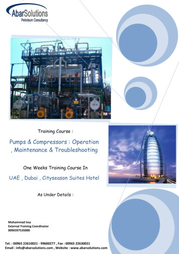
1-Product description - CompressorCompressorTM31MODELTECHNOLOGYHeavy Duty Swash PlateDISPLACEMENT313 cc (19.1 cu in) per rev.NUMBER OF CYLINDERS10REVOLUTION RANGE700-6,000 rpm (maximum peak : 7,000 rpm)DIRECTION OF ROTATIONClockwise viewed from clutchBORE36 mm (1.42 in)STROKE30.7 mm (1.21 in)SHAFT SEALLip seal typeLUBRICATION SYSTEMLubrication by gear pumpREFRIGERANTHFC-134aOIL (QUANTITY)ZXL 100 PG PAG OIL (DH-PS): 500 cc ( 30.5 cu in)WEIGHT9.5 kg (21 lb) (w/o Clutch w/o oil)278.5 - 143 - 178 (mm)10.94 - 5.63 - 7 (in)DIMENSIONS (with clutch)Length - Width - HeightMOUNTINGDirect (side or base)Saturated condensing conditionsValeo TM31 Application limits for 26tctetc : Condensing temperaturete : Evaporating gas aA1144157oF7143654PSIG22295169PSIASaturated evaporating conditions-3-oC-17teMPaG
1- Product description - Magnetic clutchSpecifications*TYPEElectromagnetic single-plate dry clutchRATED VOLTAGE24V DC or 12 V DCPOWER CONSUMPTION48 W maximumSTATIC TORQUE78 N·m {8.0 kgf·m, 58 lbf·ft}DIRECTION OF ROTATIONClockwise, viewed from clutchWEIGHTApprox 4.5 kg {10 lb}V-BELT TYPEV-groove (A or B) or V-ribbed (PK)※The above specifications may vary with the compressor.-4-
1- Product description - PerformanceThe performance data below were measured under the following conditions: Compressor speed: 1450 rpm Suction gas temperature: 20oCValeo TM31 performance data (R134a)ConditionsCond temp(oC )Pd(MPaG)400.91501.21601.58Cooling capacity Q (kW) & Power consumption P (kW)Evap temp(oC )12.5107.550-5-10Ps (MPaG)0.350.320.280.240.190.150.10P (kW)4.043.943.823.743.493.202.88Q (kW)22.6420.6118.6517.5713.6810.568.19P (kW)4.594.484.344.183.843.473.08Q (kW)21.2218.7016.5414.8511.669.066.93P (kW)5.185.004.794.594.173.723.27Q (kW)17.2515.4613.7812.329.697.465.65Valeo TM31 conversion factorsPower consumption data at different rotation speed can be approximated with the conversion factorsbelow.Conversion 045005000Compressor speed (rpm) Lip-seal type shaft sealThe compressor has a lip-seal type shaft seal. This type of shaft seal greatly improves the sealing of thecompressor to increase its performance and durability.-5-
1- Product description - Dimensions48 484-M8x1.2545 42 15845 156 (effective diameter)Unit: mm2142TM31compressors with magnetic clutch211679956Approx 178112790.3 0.6143116Approx 244Approx 278.512-M10x1.57.7222238.5Other connecting type30 2-M8x1.25-6-
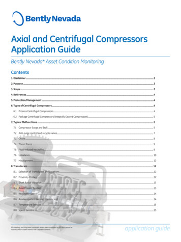
1- Product description - Exploded view619171837542201212216151413910812111. Center bolt2. Armature assembly3. Adjusting shim4. Snapring5. Pulley assembly6. Screw7. Field coil8. Bolt9. Washer10. Front cylinder head11. Shaft seal assembly12. Gasket13. Valve plate assembly14. Suction valve15. O-ring16. Cylinder shaft assembly17. Oil filler plug18. O-ring19. Strainer (option)20. O-ring21. Suction valve22. Valve plate assembly23. Gasket24. Gear pump25. Rear cylinder head-7-232425
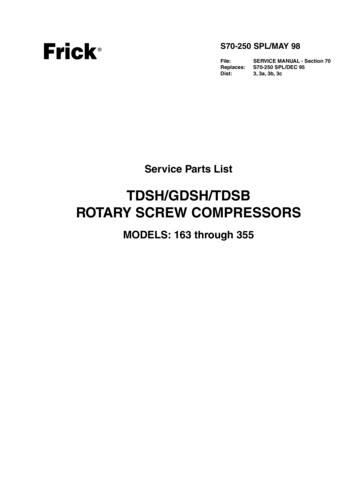
1- Product description - Swash plate systemSwash plate systemValeo TM31 are 10-cylinder swash plate typecompressors. With this type of compressors, thecylinders and pistons are arranged axially alongthe drive shaft.The pistons operate within the cylinders andare driven by a swash plate to perform suction,compression and discharge.Drive shaftThe drive shaft, which is driven by the enginethrough the magnetic clutch, is equipped with aswash plate.The drive shaft is supported by two radial bearingsand two thrust bearings.The swash plate is rotated by the drive shaft, andmoves the pistons back and forth.Radial bearingPistonThrust bearingSwash plateRadial bearingThrust bearingSuctionSuctionCompressionCompressionShoe diskBallRadial bearingPiston drive systemThe pistons in the cylinders are mounted on theswash plate through a drive ball and a shoe disk.Each piston has a compression head at each end.The rotation of the swash plate rotation resultsin a reciprocating piston movement parallel tothe drive shaft.The cylinders, which are arranged at 72 intervalsaround the drive shaft, are each divided into 2chambers, providing 5 front and 5 rear bores.As each piston performs suction and compressionat either end, the compressor operates as a 10cylinder compressor.Piston-8-
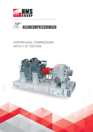
1- Product description - LubricationThe compressor is lubricated by a gear pump in the rear cylinder head which is connected to thecompressor.Oil flowWhen the compressor starts operating, the gear pump draws oil from the reservoir and pumps it throughan oil passage in the shaft.The oil then flows through ports in the shaft to lubricate the bearings and the shaft seal.The area between the swash plate and the shoe disks is lubricated by the splashing action of the oilflowing through the thrust bearings.Oil also flows through ports in the pistons to lubricate the cylinders and the pistons.Drive shaftShaft sealSwash plateRadial bearingGear pumpOil passageRadial bearingReservoirThrust bearing-9-Oil passage
1- Product descriptionCompressorCaps1. The direction of rotation is clockwise as viewedfrom the clutch side.2. Each compressor is delivered filled with aspecified quantity of compressor oil as describedon its label. The total amount of oil your airconditioning system requires is provided by thesystem designer or supplier.Operation conditions tableItemConditionSurroundingtemperatureUnder 100 C (212 F)SpeedMaximum: 7,000 rpmContinuous: 6,000 rpmPressureMaximum: 2.4 MPaG{24.5kgf/cm2,348 psig}15 3. The compressor must be operated under theconditions shown in the operation conditionstable shown at the left.CAUTION!The A/C cycle components must bedesigned so that the pressure in the cycledoes not exceed 2.4 MPaG {20 kgf/cm2,348 psig}.4. Inclination limit at installationThe compressor must be installed on thevehicle within the inclination range shown atthe left.15 5 Compressor bracket1. Install the bracket securely on the chassisframe or engine body. As the engine vibrationsmay be severe, the bracket and mounting boltsmust be installed securely.2. Vibration resistanceThere must not be any resonance under 250Hz.- 10 -
1- Product descriptionMagnetic clutch1. VoltageDC 24 VThe terminal voltage of the magnetic clutchmust exceed 21 V.DC 12 VThe terminal voltage of the magnetic clutchmust exceed 10.5 V.1 mmMagnetic clutchIdle pulley2. Ratio of magnetic clutch to drive pulley When the compressor is driven from the pulleydrive of the vehicle, the magnetic clutch todrive pulley ratio should avoid the range 1:0.92-1.08 to limit vibration and resonance. Compressor speed must not exceed thespecified speed.CAUTION!Drive pulleyPulley ratio is the ratio of the magneticclutch diameter to the drive pulley diameter.3. Pulley alignment tolerance is less than 1mm(0.04 in).4. Pulley groove: V-groove or V-ribbed.5. The belt tension must be adjusted to thetension specified by the belt maker.- 11 -
1- Product descriptionControl switchesGas type thermo switchCapillary tube1. Thermo switchA thermo switch is necessary. The followingspecification is recommended.Compressor OFF:Evaporator fin surface temperature of 0 C(32 F) or below.The thermo switch is used to prevent theevaporator from freezing.Operation temperature C ( F)DIFF4 or 3(39 or 37)ONOFFONOFF0 (32)0.19 {1.9, 27} 1.47 {15, 213}0.18 {1.8, 26}2.65 {27, 384}2. Dual pressure switchA dual pressure switch is .Compressor OFF High pressure control2.65 MPaG {27 kgf/cm2, 384 psig} orhigher Low pressure control0.18 MPaG {1.8 kgf/cm2, 26 psig} orlowerThe dual pressure switch controls high andlow pressure. High pressure controlWhen abnormally high pressure develops,the compressor is turned OFF to protect thesystem. Low pressure controlWhen there is insufficient refrigerant in thesystem, compressor operation is stopped toprevent the compressor from seizing.- 12 -
2- Operation precautions1. During the off season of the air conditioner,operate the compressor for a few minutesonce a week.2. Do not drive through water. Water maydamage the magnetic clutch, thus preventingnormal operation.3. Do not allow a compressor that has not beenused for a long period to become wet.4. Always charge the A/C system with thespecified quantity of refrigerant.5. Keep the compressor clear of water projectionwhile cleaning the vehicule.- 13 -
3- Handling instructionsMaintenance precautionsWork areaAs the components of air conditioners areparticularly sensitive to moisture, dirt and rust,always observe the following: Work indoors whenever possible Select a flat ground work area Keep the work area clean Select a work area with adequate ventilation.CAUTION!Refrigerant itself is not harmful, butexcessive accumulation in a closed area cancause oxygen deficiency. Keep open flame and inflammables away fromthe vehicle in which the air conditioner is beinginstalled.(Fire is particularly dangerous during the gasleak inspection following installation)WARNING!Contact with flame and high temperaturescan generate toxic gases.Safety glassesGlovesRefrigerant handlingWARNING!Direct contact with refrigerant can causefrostbite or blindness.Always wear safety glasses and protectivegloves.Do not work with refrigerant close to yourface.1. Do not misidentify refrigerantsIf an HFC-134a air conditioning system is mistakenlycharged with another refrigerant, serious problemssuch as compressor seizing may occur. Therefore,confirm before charging with refrigerant that thetype of air conditioning system is an HFC-134asystem.- 14 -
3- Handling instructionsDo not release refrigerant intothe airFILLAUTO2. Do not release refrigerant into the airAlthough HFC-134a is not subject to CFC regulations,it can have effect on global warming and so shouldnot be released into the air. When removingrefrigerant from the air
This service manual has been elaborated to help service personnel to provide efficient and correct service and maintenance on the TM31 (formerly called DKS 32) compressor (for HFC-134a) for auto-motive air conditioning. This manual includes the operation specifications, procedures for disassembly, reassembly, and inspection of the compressor.