Transcription
SERVICEMANUALModels:PRO2c(Serial Numbers- 1000 and above)PRO4c(Serial Numbers- 1000 and above)ISO 9001 CERTIFIED
TABLE of CONTENTSVectra ProForeword . . . . . . . . . . . . . . . . . . . . . . . . . . . . . . . . . . . . . . . .15.21 Screen Contrast Test . . . . . . . . . . . . . . . . . . . . . . . . .241- Safety Precautions . . . . . . . . . . . . . . . . . . . . . . . . . . . . . . .25.22 Zip Disk Test . . . . . . . . . . . . . . . . . . . . . . . . . . . . . . .241.1 Precautionary Symbol Definitions . . . . . . . . . . . . . . . . . .25.23 Default Setup Test . . . . . . . . . . . . . . . . . . . . . . . . . . .251.2 Safety Precautions . . . . . . . . . . . . . . . . . . . . . . . . . . . . .25.24 Conducting Tests for Channel 3 & 4 of Vectra PRO4 .252- Theory of Operation . . . . . . . . . . . . . . . . . . . . . . . . . . . .3-45.25 Stim Board Main Power Supply Circuit Test . . . . . . . .262.1 Overview . . . . . . . . . . . . . . . . . . . . . . . . . . . . . . . . . . . .35.26 Stim Board MicroCurrent Circuit Test . . . . . . . . . . . . .272.2 Power Supply Circuits . . . . . . . . . . . . . . . . . . . . . . . . . .35.27 Stim Board High Volt Circuit Test . . . . . . . . . . . . . .28-292.3 Control Board . . . . . . . . . . . . . . . . . . . . . . . . . . . . . . . .35.28 Stim Board Channels 1 and 3 Tests . . . . . . . . . . . . . .302.4 Stim Generation Board . . . . . . . . . . . . . . . . . . . . . . . . . .45.29 Stim Board Channels 2 and 4 Tests . . . . . . . . . . . . . .312.5 Ultrasound Board and Applicator . . . . . . . . . . . . . . . . . .45.30 Ultrasound Board Generator Circuit Test . . . . . . . .32-332.6 User Interface and Accessories . . . . . . . . . . . . . . . . . . .45.31 Ultrasound Board Amplifier Circuit Tests . . . . . . . .34-353- Nomenclature . . . . . . . . . . . . . . . . . . . . . . . . . . . . . . . . . . .55.32 Power Distribution Board Tests . . . . . . . . . . . . . . . . . .364- Specifications . . . . . . . . . . . . . . . . . . . . . . . . . . . . . . . . .6-76- Removal & Replacement Procedures . . . . . . . . . . . . .37-434.1 Vectra PRO Physical Specifications . . . . . . . . . . . . . . . .66.1 General . . . . . . . . . . . . . . . . . . . . . . . . . . . . . . . . . . . .374.2 Vectra PRO Stimulator Output Parameters . . . . . . . . . . .66.2 Fuse Replacement . . . . . . . . . . . . . . . . . . . . . . . . . . . .374.3 Vectra PRO Ultrasound Output Parameters . . . . . . . . . .76.3 Top & Bottom of Unit . . . . . . . . . . . . . . . . . . . . . . . . . .375- Troubleshooting . . . . . . . . . . . . . . . . . . . . . . . . . . . . . .8-366.4 Zip Drive Removal & Replacement . . . . . . . . . . . . . . . .385.1 Vectra PRO Software Error Messages . . . . . . . . . . . . .8-96.5 Fan Removal & Replacement . . . . . . . . . . . . . . . . . . . .395.2 Vectra PRO System Testing . . . . . . . . . . . . . . . . . . . . .106.6 Control Board Removal & Replacement . . . . . . . . . . . .405.3 Visual Inspection . . . . . . . . . . . . . . . . . . . . . . . . . . . . .116.7 Stim Board #2 (Vectra Pro4) Removal & Replacement .415.4 Ground Resistance Test . . . . . . . . . . . . . . . . . . . . . . . .116.8 Stim Board #1 (Vectra Pro 2 & 4)5.5 Leakage Tests . . . . . . . . . . . . . . . . . . . . . . . . . . . . . . .11Removal & Replacement . . . . . . . . . . . . . . . . . . . . . . .425.6 Unit Startup and Fan Testing . . . . . . . . . . . . . . . . . . . .126.9 Ultrasound Board Removal & Replacement . . . . . . . . .435.7 Stimulator Tests . . . . . . . . . . . . . . . . . . . . . . . . . . . . . .137- Software Installation . . . . . . . . . . . . . . . . . . . . . . . . . .44-455.8 VMS Mode Test . . . . . . . . . . . . . . . . . . . . . . . . . . . .137.1 Vectra Pro2 and Pro4 System Software and Upgrades .445.9 Interferential Mode Test . . . . . . . . . . . . . . . . . . . . . . . .147.2 Stim Board Software . . . . . . . . . . . . . . . . . . . . . . . . . .455.10 Premodulated Mode Test . . . . . . . . . . . . . . . . . . . . . .148- Ultrasound Applicator Calibration . . . . . . . . . . . . . . .46-475.11 Russian Mode Test . . . . . . . . . . . . . . . . . . . . . . . . . . .159- Technical Maintenance . . . . . . . . . . . . . . . . . . . . . . . . . .485.12 MicroCurrent Mode Test . . . . . . . . . . . . . . . . . . . . . . .16Maintenance/Troubleshooting Test Data Sheet . . . . . . . . .495.13 MicroCurrent Probe Mode Test . . . . . . . . . . . . . . . . . .175.14 High Volt Mode Test . . . . . . . . . . . . . . . . . . . . . . . . . .185.15 “Chime” Test . . . . . . . . . . . . . . . . . . . . . . . . . . . . . . .195.16 Ultrasound Tests . . . . . . . . . . . . . . . . . . . . . . . . . . . .205.17 Ultrasound Applicator Identification Test . . . . . . . . . . .205.18 Ultrasound Applicator Output Test . . . . . . . . . . . . . . . .215.19 Ultrasound Duty Cycle Test . . . . . . . . . . . . . . . . . . . .225.20 Combo Operation Test . . . . . . . . . . . . . . . . . . . . . . . .23 2001 Chattanooga Group, Inc., Chattanooga, Tennessee, USA. Any use of editorial,pictorial or layout composition of this publication without express written consent fromChattanooga Group, Inc. is strictly prohibited. This publication was written, illustratedand prepared for print by Chattanooga Group, Inc.ISO 9001 CERTIFIED
FOREWORDVectra ProRead, understand and follow the Safety Precautions and information contained in this manual.This manual contains the necessary safety, and field service information for those Field Service Technicians,approved by Chattanooga Group, Inc., to perform field service on the Vectra Pro units.At the time of publication the information contained herein was current and up to date. However, due tocontinual technological improvements and increased clinical knowledge in the field of electrotherapy, as well asChattanooga Group, Inc.’s policy of continual improvement, Chattanooga Group, Inc. reserves the right tomake periodic changes and improvements to their equipment and documentation without any obligation on thepart of Chattanooga Group, Inc.It is the sole responsibility for field technicians to stay informed and trained in the latest technology utilized inthe Vectra Pro units by Chattanooga Group, Inc. From time to time, as significant improvements areincorporated, Service Bulletins will be produced and made available on our web site (www.chattgroup.com) inlieu of reprinting a complete manual prematurely. These Service Bulletins will provide updated serviceinformation and technology improvements to the Vectra Pro for use by approved service technicians.“Approved Service Technician” Definitions;1. Level I- Those Field Service Technicians that have successfully completed the minimal training required byChattanooga Group, Inc. in basic service techniques.2. Level II- Those Field Service Technicians that have successfully completed Level I Training as well asLevel II training as required to perform specific troubleshooting and repair techniques andprocedures.3. Level III- Those Field Service Technicians that have successfully completed Levels I & II Training as well asLevel III Advanced Training as required to perform all necessary Troubleshooting and Repairtechniques. The Technician having successfully completed the three levels of training and coupledwith experience should have the ability to train other technicians in Level I and Level II Trainingwith the necessary Training Materials from Chattanooga Group, Inc.4. Temporary- Chattanooga Group, Inc., at its discretion and based on known experience of the technician,may grant a “Temporary Approval” to a field technician for particular troubleshooting and repairof a specific unit requiring immediate attention. This “Temporary Approval” in no fashionacknowledges the training level of a technician as defined above. This “Temporary Approval” isutilized only in unique situations for a specific unit for a specific service technique only and isdocumented as such.Due to the complex nature of the technology utilized by Chattanooga Group, Inc., the recommendedtroubleshooting techniques are to determine “Bad Board” and board replacement only. No board componentlevel troubleshooting is recommended nor will information or parts be supplied by Chattanooga Group, Inc. Anyboard component level troubleshooting performed will be at sole risk and liability of the Service Technicianperforming such troubleshooting techniques.This equipment is to be sold and used only under the prescription and supervision of a licensed medicalpractitioner.This equipment is to be serviced only by an “Approved Service Technician”.For Additional Service Contact:Chattanooga Group, Inc.Electrotherapy/Traction Support DepartmentToll Free: 1-866-864-05981
1- SAFETY PRECAUTIONSVectra Pro1.2 Safety PrecautionsRead, understand and follow all safety precautionsfound in this manual. Below are general safetyprecautions that must be read and understood beforeattempting any service techniques on these units.Throughout this manual specific safety precautions willbe found. Read, understand and follow all safetyprecautions.1.1 Precautionary Symbol DefinitionsThe precautionary instructions found in this manual areindicated by specific symbols. Understand thesesymbols and their definitions before operating orservicing this equipment. The definitions ofthese symbols are as follows;A. CAUTION!CAUTION!Text with a “CAUTION” indicator will explainpossible Safety infractions that have the potential tocause minor to moderate injury or damage toequipment. Read, understand and practice the precautionaryand operating instructions. Know the limitationsand hazards associated with using any electricalstimulation or ultrasound device. Observe theprecautionary and operational decals placed onthe unit. DO NOT operate the Vectra Pro when connectedto any unit other than Chattanooga Group, Inc.devices. Do not operate the unit in an environmentof short-wave diathermy use. The Ultrasound generator should be routinelychecked before each use to determine that allcontrols function normally; especially that theintensity control does properly adjust the intensityof the ultrasonic power output in a stable manner.Also, determine that the treatment time controldoes actually terminate ultrasonic power outputwhen the timer reaches zero. Use of controls or adjustments or performance ofprocedures other than those specified herein mayresult in hazardous exposure to ultrasonic energy. DO NOT use sharp objects such as a pencil pointor ballpoint pen to operate the buttons on thecontrol panel as damage may result. Operate, transport and store this unit intemperatures between 59 F and 104 F (15 Cand 40 C), with Relative Humidity ranging from30%- 60%. Inappropriate handling of, and subjecting theultrasound applicator to physical abuse, mayadversely affect its characteristics. Inspect treatment head for cracks, which may allowthe ingress of conductive fluid before each use. Inspect treatment head cables and associatedconnectors before each use.B. WARNING!CAUTIONWARNINGText with a “WARNING” indicator will explainpossible Safety infractions that will potentially causeserious injury and equipment damage.C. DANGER! DANGERText with a “DANGER” indicator will explainpossible Safety infractions that are imminentlyhazardous situations that would result in death orserious injury.D. EXPLOSION HAZARDDo not use this equipment in the presence offlammable anesthetics. This symbol is alsoprominently displayed on the serial number plate ofthe unit.E. NOTE:Throughout this manual “NOTE” may be found.The Notes are helpful information to aid in theparticular area or function being described.2
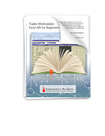
2- THEORY of OPERATIONVectra Pro2.1 OverviewThe Vectra series electrotherapy products are comprised of several PC board assemblies housed within a commonenclosure. These assemblies each support a distinct function in the product. The basic elements are User Interface,Control Board, Stim Generation Board, Ultrasound Board, Ultrasound Applicator, and Power Supply Circuits.See Figure 2.1 below.FIGURE 2.12.2 Power Supply CircuitsA universal input power supply provides all parts of the system with 12 volts DC. The supply is connected to the mainsat all times when the cord is attached. The power switches on the top of the unit, switch the 12V output of the powersupply to the different components in the system by way of the Power Distribution Board. The 12V supply is regulatedlocally at each PC board as required.2.3 Control BoardThe Control Board serves just as its name implies. It controls the operation of the stim boards, ultrasound boards, userinterface, and accessories. The control board communicates to the stim boards and ultrasound board through aproprietary 8-bit parallel bus. The control board drives the display. The control board reads the touch screen or menubuttons. The control board also reads the amplitude and contrast controls. The control board manages the ZIP drive andinfrared printer port. The control board through the power supply distribution board operates the gel warmer. Soundoutput is generated by the control board and routed to an internal speaker or alternately to external speakers. Thecontrol board reads the patient switch or manual stim switch.3
2- THEORY of OPERATIONVectra Pro2.4 Stim Generation BoardThe stim board creates all muscle stimulation output. Communications to the stim board is via an 8-bit data busand a dual-port RAM. A processor on the stim board acts on messages passed to it by the control board to set upwaveforms and adjust output amplitude. Information can likewise be passed from the stim board back to the controlboard for monitoring current, GSR mode levels, etc. If the stim board does not respond as expected to a commandfrom the control board, output is stopped and an error message is generated.2.5 Ultrasound Board and ApplicatorThe ultrasound board generates the 1 or 3.3 MHz output to drive the ultrasound applicat
Read, understand and follow the Safety Precautions and information contained in this manual. This manual contains the necessary safety, and field service information for those Field Service Technicians, approved by Chattanooga Group, Inc., to perform field service on the Vectra Pro units.