Transcription
Tutorial on Networking for Digital SubstationsRichard Hunt, Marcelo Zapella, Carlos Pimentel, Gustavo Silvano – GE Grid SolutionsIntroductionA digital substation is one where all analog interfaces, such as current and voltage measurement,equipment status and alarms, and equipment control points are converted to digitized datadirectly at their source. This digital data, published using techniques described in the IEC 61850standard, is then shared with other devices in the substation, and potentially beyond thesubstation as well. This allows substation control systems to be built faster and more efficiently,while using less materials and to unlock the value of data in the to operate the substation and itsequipment better.A digital substation therefore requires all devices in the substation to communicate with eachother over Ethernet networks. These Ethernet networks must be designed to manage the varioustypes of traffic and messages that IEC 61850 requires for sharing data between devices. Thisrequires protection and control and substation automation engineers to have some understandingof Ethernet networks. The design and management of large and complex networks that movelarge amounts of traffic is a specialized field of knowledge, which may be intimidating to powersystem engineers.However, it is not necessary for power system engineers to fully understand the complexity ofEthernet networks, but to simply understand enough to design and maintain networks that supportthe needs of a typical substation. This is actually very straightforward, as the traffic on thenetwork in the substation does not change over time, because it is based on the substationphysical design, operating requirements, and equipment, which only changes rarely, as part ofcapital projects. This means for any specific substation, the communications network can bedesigned once, and the design and configuration never need to change.In summary, the knowledge to support networking in terms of power systems, is simpler thanexpected. The next sections will introduce the main points on digital substation networking andpresent a tutorial to the engineering team on how dealing with network definitions, configurationsand validation, including a real case experience of Factory Acceptance Tests (FAT) for a digitalsubstation project.From Analog To DigitalIn conventional substations, the task of connecting protection and control equipment to signalsources requires proper engineering. Many variables are taken into account for choosing the wireinfrastructure, e.g. current, signal attenuation, signal delay. When moving to a digital substationsolution, wire infrastructure is replaced by network infrastructure, where data is transmitted fromsignal sources to protection and control equipment through the Ethernet standard. Obviously, thecomplexity of such solution is greater because all data traffics through the same physicalnetwork, there are several protocols involved and many more variables must be considered. Thismeans that even more care must be taken when engineering the network in digital substations.
The first thing to consider is bandwidth. Just like wire gauge is chosen based on current, linkspeed must be appropriate to the amount of data being transmitted. In large networks, which isusually the case for digital substations, there is a huge amount of data traffic but not all of it isrequired to reach every device. As most part of IEC 61850 data uses multicast destinationaddresses, packets are forwarded everywhere in the network, forcing every link to bedimensioned to support the total network throughput. That can be avoided using trafficsegregation, allowing each device to receive only the required data. The most commonly usedsolutions are virtual LANs (VLANs) and multicast address filtering. VLANs are great forallowing only specific data streams to traffic through a link, blocking everything else. Multicastaddress filtering, in the other hand, is best suited for blocking specific data streams to beforwarded to a link, whereas everything else flows normally.Another aspect to be considered is latency. The same way long cables will introduce signal delay,long network paths and congestions add to the time data takes to go from one point to another,usually referred to as latency. This is especially important in IEC 61850 networks, whereprotection and control equipment must respond as soon as possible to events in the electricsystem. The best way to minimize latency is to ensure sender and receiver are as close aspossible, i.e. reduce the number of hops between the devices, ideally being connected to the sameswitch. This will not only help data reach its destination faster, but also potentially reducethroughput in the so-called trunk links (connections between switches).Prioritization is also a way of reducing latency as well as improving data delivery probability.When packets are prioritized, queueing is less likely to happen, thus ensuring that they aretransmitted as fast as possible. In congestion situations when the throughput reaches the linkbandwidth and packets need to be dropped, priority ensures that important data does not get lost.This can be easily done using Quality of Service (QoS) by choosing the appropriate priority levelfor each data stream so that the most important ones are preferable.Moving from wire to network infrastructure raises reliability questions. In the analog world, thebiggest threats against data integrity are wire damage and electromagnetic interference. In thedigital world however, there are a lot more concerns, e.g. equipment failure, congestion,transmission errors. Redundancy protocols were created to address this problem. RSTP (RapidSpanning Tree protocol), PRP (Parallel Redundancy Protocol) and HSR (High-availabilitySeamless Redundancy) are the most commonly used and depending on the network architecture,one, two or all of them can be used simultaneously.Performance Requirements For IEC 61850 NetworksGeneral information reporting and control commands have been digitized for decades with theadvent of modern SCADA systems. A fully digital substation means taking the next step, whichis digitizing the interfaces between primary equipment and protective relays and bay controldevices. This interface across the switchyard is generically known as “process bus”. Process busis the best way to look at and learn networking requirements in a substation, as process bus is themost demanding application in the digital substation.Process bus requires 3 different types of messages across the Ethernet network.
GOOSE messaging. A GOOSE message contains a dataset of information. Individual datasetitems may be used for indicating equipment status and alarms, and they may be used forcontrol indications such as breaker trip and close flags. GOOSE messages will be publishedany time a dataset item changes state. GOOSE is the primary messaging between circuitbreakers and protective relays and bay control units.Sampled Values (SV) messaging. Sampled values are instantaneous samples of currents andvoltages from instrument transformers, published by merging units (MUs) to the process busnetwork. Protective relays and bay control units subscribe to this data.Precision Time Protocol (PTP) messaging. PTP is the other name for IEEE 1588 timesynchronization through the network. PTP uses message exchanges between master and slaveclocks to accurately measure and compensate for path delays between the clocks.All three of these message types are multicast messages. This means the messages are publishedto the network, and any device connected to the network can subscribe to this data.GOOSE messages, SV messages, and PTP messages will therefore be everywhere on thenetwork. With a large number of devices publishing data, it is necessary to understand how thisimpacts network bandwidth to prevent overloading of the network, and switch ports.Messaging BandwidthGOOSE transmits a heartbeat message cyclically to prove the publishing device is still alive,typically once per second. GOOSE is intended to transmit spontaneous messages on the statechange of any dataset item in the GOOSE message. To overcome possible frame loss, a GOOSEmessage retransmits some number of times up until the heartbeat message interval, One GOOSEapplication in an IED generates about 1 kbit/s of data in steady-state and about 1 Mbit/s duringspontaneous messages.The PTP message bandwidth depends on the network topology, considering the number of IEDs,the Ethernet Switch type (if it supports PTP or not) and PTP mode: peer-to-peer (P2P) or end-toend (E2E). PTP as defined for power system applications (in C37.238 or 9-3) publishes once persecond and has a bandwidth comparable to steady state GOOSE messages.While GOOSE and PTP have similar requirements on the process bus network, SV traffic is evenmore demanding, but it is easily predictable. An SV frame as specified in IEC 61850-9-2LErepresents 1 sample in an acquisition system with a sampling rate of 80 samples per cycle. Thisframe has an approximate size of 140 bytes, consuming a bandwidth of approximately 5 Mbit/s(50 Hz system) or 6 Mbit/s (60 Hz system) per stream. For measurement, the sampling rate is 256samples per cycle, with 8 samples sent in a single frame at a lower rate, resulting in a bandwidthof up to 10Mbit/s for systems at 50 Hz and 12 Mbit/s for 60 Hz.So as the number of devices on the network increases, messaging traffic consumes morebandwidth, which can decrease network performance. The goal must be to maintain overallsubstation performance, especially for protective relaying.Messaging Latency
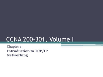
The IEC 61850-90-4 Technical Report [1] focuses on the engineering of a local network used tomeet the IEC61850 requirements for substation automation. It describes the aspects related toprotection, such as tripping over the network (GOOSE), the multicast data transfer from mergingunits with large volumes of Sampled Values and high precision clock synchronization. Amongother matters, the technical report outlines different approaches to network topology andredundancy, which will be covered in a later section.Referring to messaging performance, the technical report shows the expected IEC 61850 trafficand maximum delay of high priority messages, as in Table 1 below:Table 1: IEC 61850 Message Performance RequirementsMessageMax. DelayBandwidthApplication(ms)GOOSE (Trip)3LowProtectionGOOSE (other)10 to 100LowProtectionSampled Val.4HighProcess BusPTPLowGeneral Phasors, SVsMMS (low speed) 100LowControlMMS (med speed) 500LowControlNote there is not a maximum delay specified for PTP. The PTP network directly calculates andcompensates for the delay over each possible path, so by definition the protocol itself defines thefastest path between the devices.Tutorial for Network DefinitionsIn the substation environment, the network infrastructure must operate without the presence ofoperators and in some cases does not have connection to the Internet for remote management. Inother words, the network infrastructure must be reliable and single failure proof, the architecturesmust consider redundant paths in case of link failures and the switches operating parameters mustbe configured to ensure the flow of information even in situations of network stress. Furthermore,whenever an unexpected situation occurs, the network infrastructure must be capable ofwarning/alarming the substation supervisory for attention/assistance.Based on the application requirements, the substation infrastructure and technology definitionsinitiate by choosing the primary instrumentation, followed by protection & control devices and itsfunctionalities, their location on buildings and the data communications protocols (SV, GOOSE,PTP, SNMP, etc.). The network infrastructure definition is the next step, starting by selecting thenetworking equipment, deciding the interconnection between devices and the network topologyincluding redundancy. The last steps would be network configuration, validation from thearchitectures and redesign if necessary. To illustrate this macro workflow, Figure 1 presents theengineering steps to define the network architecture from a substation.
Figure 1 – Engineering steps for network communication definitionsNetwork equipment selectionAlthough networking equipment may have a wide list of functionalities and characteristics, tofulfill the performance requirements from a 61850 network the following main points must beobserved when selecting a networking equipment: Industry hardened design, ready to operate in harsh environment (same as relays) andpreferable with redundant power supply and dry-contact relay alarm;Number and type of Ethernet ports, depending on interconnection required betweendevices;Ports speed and switching capacity. As previously showed IEC 61850-9-2LE sampledvalues usually consumes a bandwidth of 5 Mbit/s (50 Hz system) or 6 Mbit/s (60 Hzsystem) per stream, but it may reach up to 12 Mbit/s for measurement applications. Thus,consider trunk links (connection among switches) and a few edge links (for relays, DFRs)may transmit multiple SV stream;Layer 2 functionalities, such as MAC filtering and VLANs for traffic segregation;Switching latency and Quality of Service to ensure fast and uninterrupted data switching;Transparent clock operation with hardware-based time stamping, when using IEEE1588v2 time synchronization;Support to desired redundancy protocols, such as RSTP, PRP and HSR.
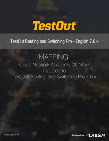
Besides the above listed points there are many others, such as Cybersecurity features to avoidmalicious attacks, SNMP for management/monitoring, IGMP for PMU applications and Layer 3functionalities in case of large substations with multiple areas, to mention a few, but the paper’sfocus is on the main network concepts.Network topology definitionA good practice while defining the network architecture is to ensure sender and receiver are asclose as possible, as this is the best way to minimize packets latency and data bandwidth in trunklinks. High throughput in trunk links can also contribute to lower latency, as data from severalports is merged into a single one and queueing may be necessary, especially when devices aresynchronized, and data is sent simultaneously. Figure 2 illustrates the difference between havingseveral streams traverse a trunk link and connecting publisher/subscriber in the same switch in away that data does not need to be forwarded to the trunk link.Figure 2 – Good practice on IEDs connections to avoid several streams in trunk linksIn addition, redundancy is a usual requirement for network topologies to avoid any single point offailure, so it is recommended to start the network design by considering full redundancy, as itmay be removed later from the parts that are do not needed. The reverse approach would requirefurther efforts, which may even lead to a complete network reengineering. Numerous protocolsprovide partial or full network redundancy on the MAC layer, the most common andrecommended by IEC 61850 are the RSTP, PRP and HSR; the concepts are described in IEC62439-1.Note that redundancy is meant to increase substation operation reliability, but it does not ensurehigh availability by itself. Device characteristics play a major role to ensure availability, byhaving a high MTBF (Mean Time Between Failure) and low MTTR (Mean Time To Repair).RSTP is the most widely used loop breaking protocol a mechanism created to solve the problemsthat arise when a loop is inserted into a LAN, as it converts a meshed network to a logical tree, byblocking ports that would introduce loops and leaving only one path available between devices asshown in Figure 3. Although RSTP is widely used for loop breaking, it provides redundancy by
recalculating a new path in the network if a trunk link failure occurs. In case of failure in the edgelink or in the Ethernet switch itself, the RSTP will also calculate a new path but the attacheddevices will be isolated from the network. As RSTP is performed by Ethernet switches and takesin the order of milli-seconds to recover from a fault, it is not well suited for the process bus, butmay be used for control and management on the station bus level.Figure 3 – Example of RSTP network topology.Different from RSTP, the redundancy protocols PRP and HSR are implemented on the enddevices, provide seamless failover operation, and protecting the system against link (trunk oredge) or even network device failures. The PRP topology is equivalent to having two process busnetworks where both operate in parallel, and in case of any failure in one, the other is used asbackup. End-devices are connected to both networks, sending and receiving packets to/from both.In summary, PRP redundancy relies on a complete duplication of network devices, meaning it isthe most effective redundant protocol but also the most expensive. An effective way of usingPRP on substation networks is by combining the process bus and the station bus on the samephysical network and segregating the buses by using virtual LANs.
Figure 4 – Example of PRP network topology.HSR operates in a ring topology, and as the protocol is supported by the devices, HSR canoperate without dedicated Ethernet switches. On a HSR network, each device sends the sameframe on both directions sail safeguarding the system against a single point of failure in the ring.Although HSR provides seamless redundancy and is cheaper than PRP, there are two mainconcerns when using a large ring in a process bus. The first is related to reliability, as once thering is composed by many devices, the possibility of two failures increase, to which the networkis not prepared for. The second is related to bandwidth, as all devices on the ring must support allthe data flow in the network. To avoid that, HSR networks are usually composed by multiplerings with a small number of devices each, and redundancy switches (Redbox) interconnectingthem all. The interconnection may rely on other topologies, such as HSR, by creating a ring ofrings (not recommended due to bandwidth limitations), or PRP (most commonly used).Figure 5 – Example of HSR network rings interconnected through a PRP network.Network configuration
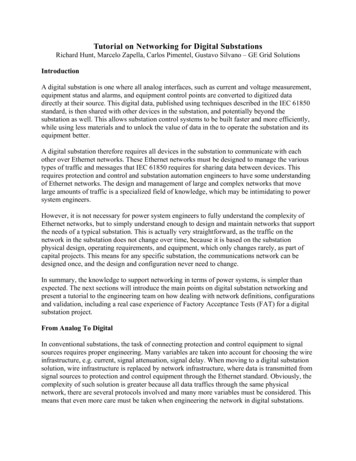
In a 61850 network, special functions may be required to ensure the switches will performappropriate treatment of substation automation traffic across the network. Defined in IEEE802.1Q [2], functions as VLANs and Quality of Service (QoS) are designed to implement flowcontrol, traffic shaping, or queuing differential services in the network. Class of Service (CoS) isused in support of QoS, and it assigns priority values to data messages in order to discipline thenetwork traffic. The basic challenge is that GOOSE, Sampled Values and Precision TimeProtocol messages are multicast, operating at the basic data link layer (Layer 2) of a networkswitch. They will pass through the entire network on a first-in, first-out basis in switch buffersunless properly managed.Virtual LAN technology allows separation of traffic through logical networks. In power systemcommunication, where IEC-61850 messages are expected with different priority and usage, therewill be only one physical path for each IED and the packets must be separated logically.When using VLAN traffic segregation, multicast messages are forwarded only onto the VLANthat the multicast message belongs to. Thus, GOOSE, Sampled Values and PTP traffic will flowseparately from each other. Finally, as the traffic is separated, IED equipment that expects toreceive only GOOSE messages will not have its network interface interrupted by Sampled Valuesdata, for example.An example of expected VLAN traffic segregation is shown in Figure 6. In this example, thereare 3 VLAN configured, one for PTP traffic, one for Sampled Values traffic and another one forGOOSE traffic. The Merging Unit is the publisher of GOOSE and Sampled Values messages,and it is the only slave clock of PTP synchronization. Note that a ring physical topology is usedfor example purposes, as it is a common physical network topology in power systemcommunication.Figure 6 –Power system communication, (a) Physical network (b) logical network usingVLAN.Lastly, to make sure high priority packets will not be dropped in the case of high traffic flow,Quality-of-Service (QoS) mechanisms must be used to ensure critical data will not be lost. TheQoS spares part of Ethernet port bandwidth to be used only by these messages. When using QoS,if low priority data reaches its bandwidth (which is the Ethernet port bandwidth minus the sparedbandwidth to high priority messages), there will be low priority data loss. High priority data willnot be affected, as it has guarantee of bandwidth. Such situation is shown in Figure 7.
Figure 7 – Packet prioritization in a high traffic flow condition.Overall, it is recommended to separate each Sampled Values stream, each GOOSE stream andPTP with a unique VLAN. That is the best way to ensure complete management of IEC 61850traffic, and avoid unnecessary load where data is not required. The priorities defined for eachmessage type in IEC 61850-90-4 should be followed when configuring QoS, which is usuallydone by setting appropriate PCP values in the VLAN tags.Figure 8 – Table 37 from IEC61850-90-4 showing the priority for each message type.FAT for Digital SubstationsA substation protection and control (PAC) system conceived using IEC 61850 provides benefitsrelated to ease of equipment installation, configuration, and project execution, as most of theinterconnection between equipment is made logically through a switched network. In thisscenario, most of the tests related to performance, interlocking operational diagrams andprotection functions can be simulated in a software-based simulator. Also, these functions can be(and should be) tested before equipment goes to the field.Thus, in a digital substation project, factory acceptance tests (FAT) should be considered as acrucial part of commissioning. A complete system FAT can be performed, where messages and
field actuations can be simulated through software. Utilities can do performance tests in theirsystem before equipment is even delivered to the field. Also, as equipment interconnection ismainly performed through logical configuration, any logical issue, protection maloperation oroperational error can be fixed during FAT, before equipment leaves the factory, in a controlledscenario.Performing the real tests during FAT, commissioning test time drastically decreases. Usinganalog interfaces, all interconnection between equipment is made through hardwired cablesbetween panels, and signals are brought from the yard through copper cables. Most ofcommissioning time is spent checking the actual interconnection of the copper cables. In aswitched network environment, where a shared network is used for all station and process busmessages, these interconnections are “virtualized” through VLANs, Multicast Filtering and QoSqueues at the switches. If the network is tested in the FAT, field tests are basically checking thesignals that go to the merging units in the yard are properly processed. So, checking analogsignals, all protection actuation and interlocking logic controls does not need to be re-done in thefield, as it was previously performed. This means that field testing time spent decreases frommonths to days or weeks, depending on the size of the substation.Main requirementsTo guarantee time savings in field services in a digital commissioning project, there are somepoints that utilities, end users and manufacturers should pay attention to: project drawings, FATrequirements, and scenario simulation.The beginning of a well-executed project of a digital substation is not so different from a projectfor a conventional one. However, as most signals in a digital substation are available to IEDsthrough a switched network, the network project should be much more detailed than it isgenerally done today. Three-line diagrams and terminal block interconnections are replaced byswitch ports configuration, VLAN, multicast MAC destination, QoS class definitions, and so on.Thus, a more detailed architecture should be represented for proper network configuration. Figure9 is a good example of how a network should be represented in a project for proper IEDconfiguration.
Figure 9 - Example of network project containing IED configuration information.In addition, FAT requirements should guarantee that the system and its performance are tested inthis controlled scenario. Therefore, all logic and protection functions should be tested in thatphase of the project. FAT plans should consider system testing not only in normal operation butalso in contingencies situations, such as overload on the network or failure in IED connections.For a completely new substation, it is required that all panels are mounted and interconnected asthey will be in field, so that a real simulation of the system is performed. Proper time must bescheduled for users to run all the necessary tests with the actual system. For a system expansion,where FAT is performed only for a few bays, utilities can use software-based traffic simulators totest network performance, and real-time power system simulation or protection test-sets to ensureprotection performance. In both situations, networking load, along with IED and switch behaviormust be verified for worst case scenarios such as when there’s a loop in the network or when atemporary overload occurs, like broadcast storms for example.Real case studyThe best way to understand FAT requirements is through an actual project. The project used inthis example is composed of a main substation and three additional bays in two adjacentsubstations. The project has in total six 220 kV bays, six 60 kV bays, one 22.9 kV bay and one 10kV bay. There is a full PRP network, where process and station bus share the same physicalinfrastructure with logical traffic segregation done using VLANs.
Figure 10 - Single Line Diagram fromexample system.Figure 11 - Process and Station Busesstrategy: single shared switched networkinfrastructure.The first step, that is, network project detailing, was executed before the FAT, so all the networkdesign details were already defined in the project. This means that the IEDs connected in eachswitch port, VLAN IDs for each stream, QoS queues, MAC destination addresses, GOOSE andSV IDs and APP IDs, were selected and described at the network project. With this information,all network configuration for each IED was done in advance by the field team.With the detailed network design, network configuration and initial checks (equipment health andnetwork status with all equipment connected), including GNSS clocks, Ethernet switches and allMerging Units were performed in two days of engineering work in factory during FAT.In this FAT, protection and control equipment was not available while the network wasconfigured and checked, so the step of having all equipment connected to check the behavior ofthe entire system in a real scenario was not performed. Even though the relays were validatedseparately using a dedicated process bus for FAT testing, this was a simulated check, not acomplete system test, so the benefits of predicting system issues before commissioning were notenjoyed. However, the IED configuration for protection and automation functions was tested, sothe main benefits of configuring and checking the IEDs before going to site could still beenjoyed. even though it could be improved, as logical interconnections for the interlockingdiagrams and the protection functions itself were tested and validated.PAC system installation at site took a few days, instead of weeks, which was clearly understoodas a benefit of a digital substation when compared to conventional systems. Also, as protectionand interlocking functions were tested in FAT, commissioning was basically checking if yardconnections to merging units were correct. This was performed by checking the IEDsmeasurements, which took much less time to complete in comparison to the usual approach.On the other hand, after connecting all IEDs to the network, some integration issues wereidentified, mainly related to time synchronization, configuration mismatch and bad networkperformance. These issues could have been predicted in FAT and would have minor impact onthe project if early detected. However, as the equipment was already installed, the impact on theproject was higher than planned, and the time on site for commissioning too.Even though the system was not fully functional as expected, the issues found didn’t prevent thesystem to start operating. As the main protection and automation functions were running, it waspossible for the substation to be energized on time. Although FAT was not performed with a fullsystem, it was enough to guarantee the safe operation of the main functions. The synchronization
protocol was temporarily replaced, so time-dependent functions, such as differential protection,continued to operate while field engineers were investigating the issues. In addition, as thesystem design implements a full PRP network, field engineers were able to perform severaldiagnostics in one network, while the other one was running normally.Final comments from real case FATAfter the project was delivered and issues presented were diagnosed, it was observed that thereare several advantages for project execution related to a full digital system using a sharedinfrastructure composed by switched network in a PRP architecture: Time spent for project execution (project, FAT and commissioning) is lower if comparedto conventional systems;Time for commissioning decreases from months to days or weeks, depending onsubstation size;Diagnosis and fixing issues can be performed in a live system, with no need to shut downtransmission lines and busbars;Protection and automat
From Analog To Digital In conventional substations, the task of connecting protection and control equipment to signal sources requires proper engineering. Many variables are taken into account for choosing the wire infrastructure, e.g. current, signal attenuation, signal delay. When moving to a digital substation