Transcription
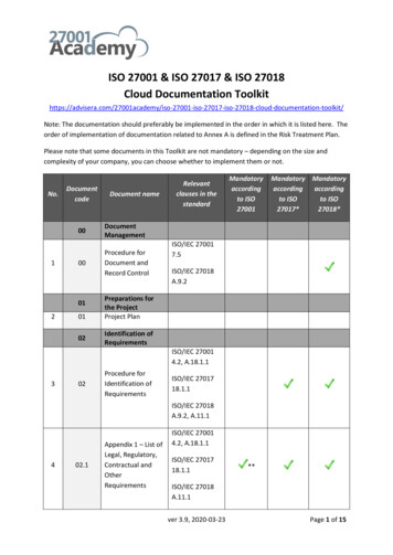
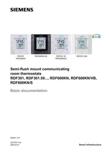
.50HSemi-flush mount communicatingroom thermostatsRDF301, RDF301.50., RDF600KN, RDF600KN/VB,RDF600KN/SBasic documentationEdition: 2.8CE1P3171en2020-02-21Smart Infrastructure
Contents1.About this document . 41.1Revision history . 41.2New functions . 51.3Reference documents . 61.41.4.11.4.21.4.3Before you start . 7Copyright . 7Quality assurance . 7Document use / request to the reader . 71.5Target audience, prerequisites . 81.6Glossary . 82.Summary . 92.1Types . 92.2Ordering . 92.3Functions. 92.4Integration via KNX bus . 112.5Equipment combinations . 132.6Accessories . 133.Functions . 143.1Temperature control . 143.23.2.13.2.2Operating modes . 15Different ways to influence the operating mode . 16Communication examples . 203.33.3.13.3.2Room temperature setpoints . 25Description . 25Setting and adjusting setpoints . 273.43.4.13.4.23.4.3Applications overview . 28Applications for fan coil systems . 29Applications for Universal systems* . 30Applications for heat pump systems . 313.5Additional functions. ol sequences . 35Sequences overview (setting via parameter P01) . 35Application mode . 362-pipe fan coil unit. 382-pipe fan coil unit with electric heater. 394-pipe fan coil unit. 41Chilled / heated ceiling and radiator applications* . 42Compressor applications. 43Setpoints and sequences . 443.73.7.13.7.2Control outputs . 46Overview . 46Control outputs configuration (setting via DIP switches or tool) . 473.8Fan control . 483.9Multifunctional input, digital input. 513.10Handling faults . 533.11KNX communications. 542 / 92Siemens .RDF301, RDF301.50., RDF600KN, RDF600KN/VB, RDF600KN/S Basic DocumentationSmart InfrastructureCE1P3171en2020-02-21
11.9S-Mode. 54LTE Mode . 54Zone addressing in LTE Mode (in conjunction with Synco) . 55Example of heating and cooling demand zone . 57Send heartbeat and receive timeout . 58Startup. 58Heating and cooling demand. 58Fault function on KNX . 59KNX switching groups (RDF600KN/S, RDF301.50, RDF301.50H only) 603.123.12.13.12.2Communication objects (S-Mode) . 62Overview . 62Description of communication objects . 633.13Communication objects (LTE-Mode) . 663.143.14.13.14.23.14.33.14.4Control parameters . 67Parameter setting via local HMI. 67Parameter setting / download via tool. 68Parameters of the "Service level" . 69Parameters of the "Expert level with diagnostics and test" . 704.Handling . 734.1Mounting and installation . 734.2Commissioning . 744.3Operation. 764.4Remote operation . 774.5Disposal . 775.Supported KNX tools . 785.15.1.1ETS . 78Parameter settings in ETS . 785.25.2.15.2.25.2.35.2.4ACS Service and Operating tool. 79Parameter settings in ACS . 80Operation and monitoring with ACS. 81Operation and monitoring with OZW772. 84Operation and monitoring with RMZ972 . 846.Connection . 856.1Connection terminals . 856.2Connection diagrams . 867.Mechanical design . 877.1General . 877.2Dimensions . 888.Technical data . 89Index913 / 92Siemens .RDF301, RDF301.50., RDF600KN, RDF600KN/VB, RDF600KN/SSmart InfrastructureBasic DocumentationCE1P3171en2020-02-21
2.52.42017-02-172016-03-282.32015-06-102.2June 20142.01.0Oct 201222 Jun 20101.About this document1.1Revision historyChanges-KNX interfaceRDF600KN/VBAdd product name RDF600KN/SUpdate KNX and ACS logoRemove universal applications for RDF301 andRDF301.50- Add notes: RDF301.50 is not suitable forapplications in heating mode without fanoperationsUpdate “Send heartbeat and receive timeout”RDF600KN changes from SW V1.8 to V2.0Presence detection function:- V1.8 with only standard presence- V2.0 with both standard presence (factory settingP77 1) and hotel presence (P77 2)Error handing and sensor errors- V2.0 with additional alarmsUpdate Synco topologyAll Units:Update mounting notes and connection diagramsregarding overcurrent protectionReplace directives with declaration document numberAdded RDF301.50HRDF600KN (SW V1.8)- Update window contact and presence detectorfunction.For all models:Update with wiring and protection informationNew S-Mode objects for Economy setpointAdded RDF600 familyFirst l57All3.10542.44.16.2811738689AllAllAllAll4 / 92Siemens RDF301, RDF301.50., RDF600KN, RDF600KN/VB, RDF600KN/SSmart InfrastructureBasic DocumentationCE1P3171en2020-02-21
1.2New functionsAvailability of new functions depends on the software version used; see tablebelow.RDF301 /RDF600KN/SRDF301.50 /RDF600KN / RDF600KN/VBRDF301.50HFirmware updatesSW V4.1SW V1.8SW V1.8SW V2.0SW l presenceStandard presence modeüExternal sensor errormessage Er3Window contactOperating mode switchovercontactFan stage in dead zone(Comfort)Fan start delayRoom temperature: S-Modeobject Economy heatingsetpointRoom temperature: S-Modeobject Economy coolingsetpointüü5 / 92Siemens .RDF301, RDF301.50., RDF600KN, RDF600KN/VB, RDF600KN/SSmart InfrastructureBasic DocumentationCE1P3171en2020-02-21
1.3SubjectRefSemi-flush mount room[1][2]thermostats with KNX[3]communications,[3a]RDF301, RDF301.50,RDF600KN, RDF600KN/VB,RDF600KN/SKNX Manual[4]Synco and KNX ng documentsApogeeengineering ][19][20][21]Reference documentsDoc No.DescriptionCE1N3171 Data SheetCE1B3171 Operating InstructionsCE1M3171 Mounting Instructions RDF301.CE1M3076.3 Mounting Instructions RDF600KN Handbook for Home and Building Control – Basic e en&product type category books&product type handbook)CE1N3127 KNX bus, Data SheetCE1P3127 Communication via the KNX bus for Synco 700, 900 andRXB/RXL, Basic DocumentationXLS template Planning and commissioning protocol,in HITcommunication Synco 700CE1N3121 RMB795 central control unit, Data SheetCE1Y3110 KNX S-Mode data points-Product data for ETSCE1J3110ETS product data compatibility list0-92168en Synco Application ManualCM1Y9775 Desigo RXB integration – S-ModeCM1Y9776 Desigo RXB / RXL integration – Individual AddressingCM1Y9777 Third-party integrationCM1Y9778 Synco integrationCM1Y9779 Working with ETS565-132Installation Instructions: KNX driver for PXC Modular127-1676Technical Spec Sheet: KNX driver for PXC Modular140-0804Technical reference for KNX driver140-0804Application 6205 point map for RDF6 / 92Siemens RDF301, RDF301.50., RDF600KN, RDF600KN/VB, RDF600KN/SSmart InfrastructureBasic DocumentationCE1P3171en2020-02-21
1.41.4.1Before you startCopyrightThis document may be duplicated and distributed only with the express permissionof Siemens, and may be passed only to authorized persons or companies with therequired technical knowledge.1.4.2Quality assuranceThis document was prepared with great care.· The contents of this document are checked at regular intervals· Any corrections necessary are included in subsequent versions· Documents are automatically amended as a consequence of modifications andcorrections to the products describedPlease make sure that you are aware of the latest document revision date.If you find lack of clarity while using this document, or if you have any criticisms orsuggestions, please contact the Product Manager in your nearest branch office.The addresses of the Siemens Regional Companies are available nt use / request to the readerBefore using our products, it is important that you read the documents suppliedwith or ordered at the same time as the products (equipment, applications, tools,etc.) carefully and in full.We assume that persons using our products and documents are authorized andtrained appropriately and have the technical knowledge required to use ourproducts as intended.More information on the products and applications is available:· On the intranet (Siemens employees only) 23/default.aspx· From the Siemens branch office near youwww.buildingtechnologies.siemens.com or from your system supplier· From the support team at headquarters fieldsupport-zug.ch.sbt@siemens.com ifthere is no local point of contact.Siemens assumes no liability to the extent allowed under the law for any lossesresulting from a failure to comply with the aforementioned points or for theimproper compliance of the same.7 / 92Siemens .RDF301, RDF301.50., RDF600KN, RDF600KN/VB, RDF600KN/SSmart InfrastructureBasic DocumentationCE1P3171en2020-02-21
1.5Target audience, prerequisitesThis document assumes that users of the RDF KNX thermostats are familiar withthe ETS and/or Synco ACS tools and able to use them.It also presupposes that these users are aware of the specific conditions associated with KNX.In most countries, specific KNX know-how is conveyed through training centerscertified by the KNX Association (see www.knx.org/).For reference documentation, see section 1.2.1.6GlossaryThe inputs, outputs and parameters of an application can be influenced in variousways. These are identified by the following symbols in this document:Parameters identified by this symbol are set using ETS.ETSSTOPACSParameters identified by this symbol are set using the ACS tool.Note!Setting RDF KNX parameters is only supported by the following toolversions:– ETS3 or higher– ACS version 5.11 or higherInputs and outputs identified by this symbol communicate with other KNX devices.They are called communication objects (CO).The communication objects of the RDF KNX thermostats work partly in S-Mode,partly in LTE Mode, and partly in both. These objects are described accordingly.A list of the parameters is shown in section 3.13.8 / 92Siemens RDF301, RDF301.50., RDF600KN, RDF600KN/VB, RDF600KN/SSmart InfrastructureBasic DocumentationCE1P3171en2020-02-21
RDF301RDF301.50 4)RDF301.50H 3)RDF600KNRDF600KN/VBRDF600KN/S 4)Summary2.1TypesOperatingvoltageStock 770-T430S55770-T400Control outputs3-posON/OFF1 1)1 1)1 1)1 1)1 1)1 1)2 1)2 1)2 1)2 1)2 1)2 1)AC 230 VAC 230 VAC 230 VAC 230 VAC 230 VAC 230 VSuitableconduitbox 2)Product no.2.squaresquaresquareround or squareround or squareround or square1)Selectable: ON/OFF or 3-position.2)Square conduit box.3)Control outputs: KNX switching groups (Hotel: MUR, DND)4)Control outputs: KNX switching groupsColorWhiteWhiteWhiteWhiteBlackWhiteRound CEE conduit box min 60 mm diameter and min 40 mm depth.·2.2MUR: Make Up Room, DND: Do Not Disturb.Ordering· When ordering, please indicate both product no. / stock no. and name:E.g. RDF301 / S55770-T104 room thermostat.· Order valve actuators separately.2.3UseFunctionsFan coil units via ON/OFF or modulating control outputs:· 2-pipe system· 2-pipe system with electric heater· 4-pipe systemChilled / heated ceilings (or radiators)* via ON/OFF or modulating controloutputs:· Chilled / heated ceiling· Chilled / heated ceiling with electric heater· Chilled / heated ceiling and radiator / floor heating* Not applicable for RDF301, RDF301.50Compressors: Via ON/OFF control· 1-stage compressors in DX type equipment· 1-stage compressors in DX type equipment with electric heaterThe room thermostats are delivered with a fixed set of applications.The relevant application is selected and activated during commissioning usingone of the following tools:· Synco ACS· ETS· Local DIP switch and HMI9 / 92Siemens .RDF301, RDF301.50., RDF600KN, RDF600KN/VB, RDF600KN/SSmart InfrastructureBasic DocumentationCE1P3171en2020-02-21
Features······Type of mounting /suitable conduit boxes· RDF600KN for round CEE conduit box, with min 60 mm diameter,min 40 mm depth or recessed square CEE conduit boxwith 60.3 mm fixed centers· RDF301 for recessed square CEE conduit boxwith 60.3 mm fixed centersFunctions· Room temperature control via built-in temperature sensor or external roomtemperature / return air temperature sensor.· Changeover between heating and cooling mode (automatic via local sensor orbus, or manually).· Selection of applications via DIP switches or commissioning tool.· Select operating mode via operating mode button on the thermostat.· Temporary Comfort mode extension.· 1- or 3-speed fan control (automatically or manually).· Display of current room temperature or setpoint in C and/or F.· Minimum and maximum limitation of room temperature setpoint.· Button lock (automatically or manually).· 2 multifunctional inputs, freely selectable for:– Sensor for automatic heating / cooling changeover– External room temperature or return air temperature sensor– Dew point sensor– Electric heater enable– Fault input– Monitor input for temperature sensor or switch stateRDF301 – Operating mode switchover contact (keycard, window contact, etc.)RDF600KN :– Window contact– Presence detector (Standard presence mode and Hotel presence )See pages 15 & 18.· Advanced fan control function, e.g. fan kick, fan start, selectable fan operation(enable, disable or depending on heating or cooling mode).· "Purge" function together with 2-port valve in a 2-pipe changeover system.· Reminder to clean fan filters (adjust with P62).· Floor heating temperature limitation.· Reload factory settings for commissioning and control parameters.Operating modes: Comfort, Economy (Energy Saving) and ProtectionON/OFF or 3-position control outputs (relay)Output for 3-speed or 1-speed fanAutomatic or manual heating / cooling changeoverBacklit displayAC 230 V operating voltage10 / 92Siemens RDF301, RDF301.50., RDF600KN, RDF600KN/VB, RDF600KN/SSmart InfrastructureBasic DocumentationCE1P3171en2020-02-21
2.4Integration via KNX busThe RDF room thermostats can be integrated as follows:· Integration into Synco 700 system via LTE Mode (easy engineering).· Integration into Synco living via group addressing (ETS).· Integration into Desigo and Apogee via group addressing (ETS) orindividual addressing.· Integration into third-party systems via group addressing (ETS).The following KNX functions are available:· Central time program and setpoints, e.g. when using the RMB795 centralcontrol unit.· Outside temperature or time of day via bus displayed on thermostat.· Remote operation and monitoring, e.g. using the RMZ792 bus operator unit.· Remote operation and monitoring with web browser using the OZW772 webserver.· Maximum energy efficiency due to exchange of relevant energy information,e.g. with Synco 700 controllers (e.g. heating demand, cooling demand).· RDF301.50 and RDF600KN/S only: 4 buttons to control KNX actuators via KNXS-Mode("switching groups" with functions such as switching, dimming, blinds control,8-bit scene).· RDF301.50H only: 4 buttons for Hotel applications to control via KNX S-Mode.Same functions as RDF301.50, but with dedicated button labels for hotelapplications: Make Up Room, Do Not Disturb.· Alarming, e.g. external fault contact, condensation, clean filter, etc.· Monitoring input for temperature sensor or switch.Engineering and commissioning can be done using – local DIP switches / HMI– Synco ACS service tool– ETSSynco 700The RDF room thermostats are especially tailored for integration into the Synco700 system and operate together in LTE Mode. This extends the field of use ofSynco for individual room control in conjunction with fan coil units, VAV, chilledceilings and radiators.Synco livingThanks to S-Mode extension to the QAX9x3 central apartment unit, communicatingroom thermostats can be easily integrated into Synco living systems. Using the SMode data points of the central apartment unit, additional room information can beexchanged with the room thermostat via KNX TP1 (RF function is not available onthe room thermostats). To make the integration, the ETS engineering tool isrequired.11 / 92Siemens .RDF301, RDF301.50., RDF600KN, RDF600KN/VB, RDF600KN/SSmart InfrastructureBasic DocumentationCE1P3171en2020-02-21
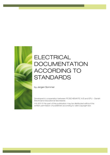
Synco topologyRDF600KN/SLegend:Synco 700Synco livingRDG., RDF OZW772RMZ792QAW.ACSRXBQAXDesigo, Apogee andthird-party systemsBuilding automation and control system (BACS)Room automation and control systemRoom thermostatsWeb serverBus operator unitRoom unitService tool using OCI702 (OCI702 are delivered with aservice cable which can be plugged into the serviceconnector on a Synco controller)Room controllersRoom unit for RXB room controllersThe RDF KNX devices can be integrated into the Siemens building automation andcontrol systems (BACS) Desigo / Apogee or into 3rd-party systems. For integration,either S-Mode (group addressing) or individual addressing can be used.12 / 92Siemens RDF301, RDF301.50., RDF600KN, RDF600KN/VB, RDF600KN/SSmart InfrastructureBasic DocumentationCE1P3171en2020-02-21
2.5Equipment combinationsDescriptionCable temperature sensor orchangeover sensorON/OFF actuatorsData sheet*)QAH11.11840Room temperature sensorQAA321747Condensation monitorQXA21.A6V10741072Electromotoric ON/OFF actuatorSFA21.4863Electromotoric ON/OFF valve andactuatorMVI /MXI A6V11251892SUA 4832Thermal actuator (for radiator valves)NOThermal actuator(for small valves 2.5 mm), NCElectrical actuator, 3-position(for radiator valves)Electrical actuator, 3-position(for 2- and 3-port valves / V P45)Electrical actuator, 3-position(for small valves 2.5 mm)Electrical actuator, 3-position(for small valves 5.5 mm)STA23.4884STP23.4884SSA31.4893SSC314895SSP31 4864SSB31.4891Electrical actuator, 3-positionSAS31 4581(only available in AP, UAE, SA and IN)Zone valve actuator(only available in AP, UAE, SA and IN)3-position actuatorsProduct no.*) The documents can be downloaded from http://siemens.com/bt/download.Note:For the maximal number of actuators in parallel, refer to information in the data sheetsof the selected actuators and to this list, depending on which value is lower:· Parallel operation of max 6 SS actuators (3-pos) is possible.· Parallel operation of max 10 ON/OFF actuators is possible.2.6AccessoriesDescriptionProduct no / SSNChangeover mounting kit(50 pcs/package)Plastic mounting bracket for semi-flushmount thermostats RDF301. forincreasing the headroom in the conduitbox by 10mmKNX Power supply 160 mA (Siemens BT LV)KNX Power supply 320 mA (Siemens BT LV)KNX Power supply 640 mA (Siemens BT LV)ARG86.3DatasheetN3009ARG70.3N30095WG1 125-1AB025WG1 125-1AB125WG1 125-1AB22----13 / 92Siemens .RDF301, RDF301.50., RDF600KN, RDF600KN/VB, RDF600KN/SSmart InfrastructureBasic DocumentationCE1P3171en2020-02-21
3.Functions3.1Temperature controlGeneral note:ParametersSetting of the control parameters (P01, etc., mentioned throughout the document)is described in section 3.13.Temperature controlThe thermostat acquires the room temperature via built-in sensor, external roomtemperature sensor (QAA32), or external return air temperature sensor (QAH11.1),and maintains the setpoint by delivering actuator control commands to heatingand/or cooling equipment. The following control outputs are available:· ON/OFF control (2-position)· Modulating PI/P control with 3-position control output (only for 2-pipeapplications)The switching differential or proportional band is 2 K for heating mode and 1 K forcooling mode (adjustable via parameters P30 and P31).The integral action time for modulating PI control is 5 minutes (RDF301.) and 45minutes (RDF600KN, RDF600KN/VB), adjustable via parameter P35.DisplayThe display shows the acquired room temperature or the Comfort setpoint, selectable via parameter P06. The factory setting displays the current room temperature.Use parameter P04 to change the room temperature display from C to F asneeded.The acquired room temperature (internal or external sensor) is also available asinformation on the bus.Room temperature· With automatic changeover or continuous heating / cooling, symbols/indicate that the system currently heats or cools (heating or cooling output isactivated).· With manual changeover (P01 2), symbols/indicate that the systemcurrently operates in heating or cooling mode. Thus, the symbols are displayedeven when the thermostat operates in the neutral zone./Concurrent display of C and FOutside temperature viabusConcurrent display of the current temperature or setpoint in C and F (parameterP07 1) is possible on the thermostats.The outside temperature can be displayed on the room thermostat by settingparameter P07 2. This temperature value has only information character.In LTE Mode, the outside temperature can only be received on outside temperaturezone 31.In S-Mode, the corresponding communication object needs to be bound with aKNX sensor device.Time of day via bus can be displayed on the room thermostat by setting parameterP07 3 or 4. The display format is either in 12- or in 24-hour format.The information can be received from a Synco controller with time masterfunctionality or any other KNX device if the corresponding communication object isbound.Time of day via busNote:· When an application program is downloaded to the Synco devices via ETS, thecorrect group addresses need to be downloaded as well to display the time ofday on the room thermostat (see Synco Knowledge Base - KB771).14 / 92Siemens RDF301, RDF301.50., RDF600KN, RDF600KN/VB, RDF600KN/SSmart InfrastructureBasic DocumentationCE1P3171en2020-02-21
3.2Operating modesThe thermostat's operating mode can be influenced in different ways (see below).Specific heating and cooling setpoints are assigned to each operating mode.The thermostat sends the effective room operating mode on the bus.Room operating mode:StateThe following operating modes are available:Auto TimerIn Auto Timer mode the room operating mode is commanded via bus.Auto Timer is replaced by Comfort when no time schedule via bus is presentComfortIn Comfort mode, the thermostat maintains the Comfort setpoint. This setpoint canbe defined via parameters P8, P9 and P10.It can be locally adjusted via the /- buttons or via bus.In Comfort mode, the fan can be set to automatic or manual fan speed: Low,medium or high.Standard presence mode:The thermostat switches to Comfort mode when the presence detector (local or onKNX) is active (room is occupied). *)Presence detector(RDF600KN )Hotel presence mode:When hotel guests leave their rooms, the thermostat switches to Economy modeand the local HMI (keys) is locked. Upon occupancy, the thermostat returns to theprevious operating mode set by the hotel guests.EconomyRoom operating mode:Window state(RDF301 )ProtectionThe setpoints (less heating and cooling than in Comfort mode) can be defined viaparameters P11 and P12.The thermostat switches to Economy mode when.– the operating mode button is pressed (only possible if parameter P02 is set to 2)– Economy is sent via bus– an operating mode switchover contact on RDF301 (e.g. keycard contactpresence detector, window contact) is active. *)- "Window state" is sent to the RDF301 via bus, e.g. from a KNX switch or a KNXpresence detector (P02 is irrelevant) *)In Protection mode, the system is.– protected against frost (factory setting 8 C, can be disabled or changed viaP65)– protected against overheating (factory setting OFF, can be enabled or changedvia P66)No other operating mode can be selected locally if Protection mode is commandedvia bus.andare displayed.Room operating mode:Window state(RDF600KN )Note:The thermostat switches to Protection mode when.– the operating mode button is pressed– Protection is sent via bus– the window contact on RDF600KN, RDF600KN/VB is active (open window).– "Window state" is sent to the RDF600KN, RDF600KN/VB via bus, e.g. from aKNX switch *)*) Refer to chapter 3.2.1 for detail regarding the operating mode switchovercontact (RDF301.), window contact (RDF600KN ) and presence detector(RDF600KN ).15 / 92Siemens .RDF301, RDF301.50., RDF600KN, RDF600KN/VB, RDF600KN/SSmart InfrastructureBasic DocumentationCE1P3171en2020-02-21
3.2.1Source for change ofope
RDF600KN/VB RDF301.50 RDF600KN/S RDF301.50H Semi-flush mount communicating room thermostats RDF301, RDF301.50., RDF600KN, RDF600KN/VB, RDF600KN/S Basic documentatio