Transcription
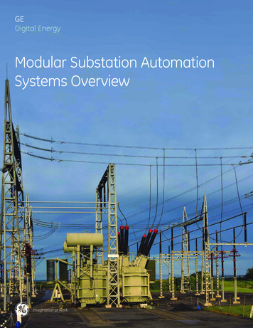
Project Code: APM-IEC-61850-2013A System Solution for IEDs Based on IEC 61850Smart Grid and IEDA smart grid is an electrical grid that uses information and communicationstechnology to gather and act on information, such as information about thebehaviors of suppliers and consumers, in an automated fashion to improvethe efficiency, reliability, economics, and sustainability of the production anddistribution of electricity. The intelligent electronic device (IED) is a basicelement of the smart grid, delivering the sensing, measurement, protection,and control functionality required by the OCESS BUSIEDPOWERQUALITYDigital Substation and IEC 61850 StandardA smart grid in a power transmission and distribution system means powerautomation and substation digitalization plays a major role in this. Moderndigital power substation designs now favor IEC 61850 as a means of tying thesystem HERIEDSSTATION BUSAll the IEDs will communicate with each other based on the IEC 61850standard. IEC 61850 features include: data modeling, reporting schemes, fasttransfer of events (GOOSE and GSSE), setting groups, digital sampling datatransfer (SV), commands configuration, and data storage.Main Challenges and IED Design ConsiderationsComplicated Communication Protocol and Multiple Communication StacksThere are several different protocols that can be mapped to the IEC 61850. An MMS stack based on TCP/IP is used to handle the server-client type communication,which is very complicated but general has low real-time requirement; GOOSE, which is used for exchanging the substation event information, requires a verylow latency; SMV messages should always be real-time and come within a very precise time slot.Real-Time Signal Processing and System Level Functional SafetyIn modern IEDs, like protection relay devices or power quality analyzer, a DFT or FFT based algorithm is widely used to detect the over current fault condition orharmonic content. In some extreme cases, the IEDs designer wants a processor to handle more than 60 channels of FFT in just several hundred microsecond.Combined with the complicated communication tasks required by IEC 61850, the IED designers start to realize that a single core processor is now reaching itslimitation.On the other hand, the power line protection devices should never fail even if something abnormal happens on the communication network.Driven by both requirements above, IED designers are now using at least two proce ssors for separation of signal processing and communication tasks. Now,the IED designer has to face another question: how do these processors communicate with each other and how efficient is that communication?Global SynchronizationDigital substations require global level synchronization, which means all of the devices in the substation should be able to align their sampling points with thesame time reference. PPS, IRIG-B or IEEE1588, is widely used for the time synchronization. IEEE1588 is based on Ethernet and has very high timing accuracyleading to the probability that it will become a standard timing synchronization protocol in digital substation in the near future.System Cost and Development CostWhen we are talking about the multiprocessor system, we usually need to consider the following questions: are the processors the same? How will theycommunicate with each other? Can they share the same system memories and power supply or must they have separated memories and power system fordevelopment do we need two development tools, two operation systems?“Platform” DevelopmentWhen the system becomes more and more complex, the development cost and time to marketing now become more and more important. Nowadays, mostIED design teams are dreaming of a common platform (including hardware and software), which can cover both high end and low end products. The platform(hardware and software) should be easily expanded and upgraded. An operation system like Linux could be welcomed due to its sufficient open resources.However, Linux is not real-time and knowing how to keep real-time performance in a system when using Linux is a serious topic.energy.analog.com
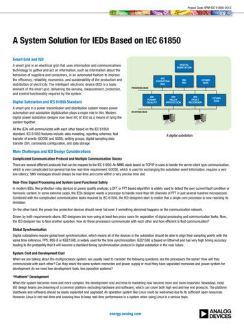
ADI IEC 61850 Demo DesignA joint project between ADI and DiGiGrid (ADI third party) was started in 2012 to develop a general platform that focuses on digital substation IEDs, whichrequires IEC 61850. Dual core Blackfin processor—ADSP-BF60x (2 500 MHz) 16 MB NOR 4 MB SPI 2 GB NAND Flash 4 Ethernet ports (two on processor with IEEE1588, two on FPGA) Cyclone IV FPGA 16-channel analog input (2 AD7606) Additional I/O board with 11-channel voltage and current transformer and8 DI, 8 DO 2 UART (1 RS-232, 1 RS-485) 128 MB, 16-bit AN5V3 MCTIINADP21191.0VADP21191.25VCAN4 UART2AD76064 RTAD8275AD8657FPGASYSTEM MEMORYBUSCONTROLLER BOARD8 LAYERS PCBPPS SIGNAL FROM IEEE15881PPS, IRIG-BHardware Consideration of IEC 61850 Demo DesignUsing ADI’s ADSP-BF60x Blackfin Processor Powerful 2 500 MHz dual core processor (60 channels, 32 points, 16-bit FFT in 0.17 ms with single core) Each core has private 148 kB L1 SRAM 128 kB/256 kB L2 SRAM for dual core data exchange System crossbar bus system makes concurrent memory and peripheral access possible 2 UART, 1 CAN, 2 SPI, 3 SPORT, 2 TWI (I2C) and 1 USB Separated DDR bus and system local memory bus make concurrent external memory access possible Safety functionality like L2 SRAM ECC, dual watchdog, system protection Dual ethernet MAC with IEEE1588v2A System Solution for IEDs Based on IEC 61850ETHERNETPHY.VIN RMIIMAC1LCD240 128FLASH16 CHS DIDOIO BOARD JUMPER5VANALOGIIN2USB TO 232ADM13305SYSTEM VOLTAGESUPERVISORY
SYSTEM CONTROLBF CORE 0BF CORE 1L2 MEMORYPERIPHERALSPOWER MGTDUAL CRCDUAL WATCHDOGTRIGGER ROUTINGL1 SRAM148kBWITH PARITYL1 SRAM148kBWITH PARITY2 TWIL2 SRAMWITH ECC256kB(BF606128kB)8 TIMERS1 COUNTER1 CANSYSTEM DEBUG2 PWM2 UARTSYSTEM CROSSBARAND DMA SUBSYSTEMSYSTEM PROTECTION2 SPI3 SPORT ACMHARDWARE PROCESSINGADSP-BF608/ADSP-BF609 ONLYL3 MEMORY ESSOR(PVP)3 EPPI1 EMMC/RSIPIXELCROSSBARPIXEL COMPOSITOR(PIXC)164 LINK PORT112 GPIO 6 PINTWATCH POINTS2 EMAC 15881 USB OTG MP16One good reason for using ADI’s ADSP-BF60x is because it has dual independent processors inside that can run at up to 500 MHz each. Another good reasonis it has two independent Ethernet MACs (two MAC addresses) which make it very suitable for IEC 61850 applications. In this demonstration system, Core 0runs the μCLinux operation system which handles non real-time tasks like MMS stacks, LCD and keypads, and other server applications like TFTP. Core 1 runsthe sampling tasks and relay protection algorithm (DFT) and can send out GOOSE messages without the intervention of the operation system. The dual corescommunicate to each other via L2 on-chip memory, which can run up to 250 MHz to ensure the highest data exchange efficiency.In some HV IEDs (110 kV and above), there may be a need for more Ethernet ports (dedicated Ethernet port for GOOSE and SMV) and the demo board also offersthe possibility to add more Ethernet ports via an FPGA. The communication interface here is important because the bandwidth of this interface determines thereal-time performance of SMV message. The ADSP-BF60x has 4 link port interfaces which offer up to 125 Mb/s each providing sufficient bandwidth to pull inthe SMV data real time.Other ADI Featured Products in the Demo BoardPart NumberDescriptionKey FeaturesBenefitsProcessorADSP-BF606/ADSP-BF607Dual core Blackfin DSP400 MHz/500 MHz dual core processor, 2 148 kB L1 SRAM, 128 kB/256 kBSRAM, system bus crossbar, dual ethernet MAC with IEEE1588High performance dual core processor withdual IEEE1588 Ethernet8-channel, 16-bitsimultaneous ADCTrue bipolar analog input ranges: 10 V, 5 V, single 5 V analog supply, 2.3 V to 5 V VDRIVE, 1 MΩ analog input impedance, analog input clamp protection8-channel simultaneous sampling AFE withsingle 5 V supplyVoltage referenceInitial accuracy 0.05% with drift 3ppm/ C, high output current: 10 mA,High performance (3 ppm), high outputdifferent output voltage option 2.5 V, low noise (0.1 Hz to 10.0 Hz): 1.75 μV p-pcurrent: 10 mAat 2.5 V outputAD8275Difference op ampFixed gain 0.2, 10 V/ 10 V to 0 V/4 V level translation with single supply,1 ppm/ C gain drift, 80 dB CMRR, 40 V to 35 V OVP with single 5 V supply,rail-to-rail outputAD8657Low power high precisiondual op ampLow power (22 μA), RRIO, low offset voltage (350 μV max), unity gain stable, dual Low power, low cost, low offset voltage dualop ampop ampIsolated RS-485/RS-422transceiverHalf or full duplex, 500 kbps, 5 V or 3.3 V operation, 3 in 1 (power isolation, signalisolation, and RS-485 driver)ADCAD7606Voltage ReferenceADR421BAmplifier 10 V to 0 V/4 V level translation with single5 V supply, 16-bit ADC driverInterfaceADM2587ERS-485 with integrated isolated dc-to-dcconverter, 15 kV/ 15 kV ESD protectionenergy.analog.com 3
Part NumberADM3053DescriptionKey FeaturesIsolated CAN transceiverBenefitSignal and power isolated CAN transceiver, complies with ISO 11898 standard,high speed data rates up to 1 Mbps, 3 in 1 (power isolation, signal isolation, andCAN transceiver)CAN bus Interface with integrated isolateddc-to-dcPower ManagementADP7104LDOLDO which can be used as the power supply500 mA output current, VIN up to 20 V, PSRR performance of 60 dB at 10 kHz whensourced from ac-to-dc to 16 bits aboveVOUT 3.3 V, initial accuracy: 0.8%, reverse current protectionanalog systemADP2119Synchronous, step-downdc-to-dc regulators145 MΩ and 70 MΩ integrated MOSFETs, input voltage range from 2.3 V to 5.5 V,output voltage from 0.6 V to VIN, continuous output current: 2 AHigh efficiency 2 A ac-to-dc regulator withintegrated MOSFETADP2384Synchronous, step-downdc-to-dc regulatorInput voltage: 4.5 V to 20 V, integrated MOSFET: 44 MΩ/11.6 MΩ, continuousoutput current: 4 A, 180 out-of-phase clock synchronization,very high efficiencyHigh efficiency 4 A ac-to-dc regulator withintegrated MOSFETADM13305Dual processor powersupply supervisorsDual supervisory circuits with pretrimmed threshold options: 1.8 V, 2.5 V, 3.3 V, and Dual processor power supply supervisors5 V, watchdog integrated, maximum supply current of 40 μAwith watchdogSoftware Consideration of IEC 61850 Demo Design Core 0 runs μCLinux and non real-time tasks like MMS stacks, LCD and keypads, TFTP serve; Ethernet Port 0 is linked to Core 0 (MMS) All μCLinux kernels, customized u-boot make files, and μCLinux drivers are given by source code and image SISCO-MMS lite stack is ported on μCLinux (SISCO-MMS license is not included in the demo kit and needs to be purchased additionally) A simple modeling example shows how to map a basic relay protection function to the related logic device (LD) and logic node (LN)—the example is given inthe demo kit with source code Core 1 runs real-time tasks (relay protection algorithm, GOOSE publish) without operation system; Ethernet Port 1 is linked to Core 1 (GOOSE) Relay protection algorithm is given by source code Real-time GOOSE publish is given by assembly source code (need to contact DiGiGrid in case C source code is required)μCLinux APPLICATIONLCD/KEYBOARD/USB/UARTIEC 61850 MMSTFTPOTHERAPPSADSP-BF60x SOFTWARERELAY PROTECTIONALGORITHMADSP-BF60xµCLinux BSPAD7606 DRIVERHARDWARE DRIVERL2-SMEMCORE 0REAL-TIME GOOSEETHERNET DRIVERCORE 1Circuits from the Lab Reference Circuits Layout considerations for an expandable multichannel simultaneous sampling data acquisition system (DAS) based on the AD7606 16-bit, 8-channel DAS(CN0148)—www.analog.com/CN0148 A low cost, 8-channel, simultaneously sampled, data acquisition system with 84 dB SNR and excellent channel-to-channel matching (CN0175)—www.analog.com/CN0175 Half-duplex, isolated RS-485 interface (CN0031)—www.analog.com/CN0031 More reference circuits are available at www.analog.com/circuitsOther Useful Links ADSP-BF60x related resources—www.analog.com/BF609 ADI DSP development environment (CCES)—www.analog.com/adswt-cces ADI μCLinux related resources—docs.blackfin.uclinux.org/doku DiGiGrid (ADI IEC 61850 third party)—www.digigrid.com.cn/productview.asp?/344 A System Solution for IEDs Based on IEC 61850
A Picture of the Demo KitIf you need more ADI energy applications and products information,please visit: energy.analog.com.Customer Interaction CenterTechnical Hotline 1-800-419-0108 (India)1-800-225-5234 (Singapore)0800-055-085 (Taiwan)82-2-2155-4200 (Korea)Email cic.asia@analog.comEngineerZone ez.analog.comFree Sample www.analog.com/sampleenergy.analog.com 5
Analog Devices ChinaAsia Pacific Headquarters22/F One Corporate Ave.222 Hu Bin RoadShanghai, 200021ChinaTel: 86.21.2320.8000Fax: 86.21.2320.8222Analog Devices, Inc.Korea Headquarters6F Hibrand Living Tower215 Yangjae-DongSeocho-GuSeoul, 137-924South KoreaTel: 82.2.2155.4200Fax: 82.2.2155.4290Analog Devices, Inc.Taiwan Headquarters5F-1 No.408Rui Guang Road, NeihouTaipei, 11492TaiwanTel: 886.2.2650.2888Fax: 886.2.2650.2899Analog Devices, Inc.India HeadquartersRmz - Infinity#3, Old Madras RoadTower D, Level 6Bangalore, 560 016IndiaTel: 91.80.4300.2000Fax: 91.80.4300.2333Analog Devices, Inc.Singapore Headquarters1 Kim Seng PromenadeGreat World CityEastTower, #11-01Singapore, 237994SingaporeTel: 65.6427.8430Fax: 65.6427.8436 2013 Analog Devices, Inc. All rights reserved.Trademarks and registered trademarks are theproperty of their respective owners.BR11504-0-4/13energy.analog.com
transfer of events (GOOSE and GSSE), setting groups, digital sampling data transfer (SV), commands configuration, and data storage. Main Challenges and IED Design Considerations Complicated Communication Protocol and Multiple Communication Stacks There are several different protocols that can be mapped to the IEC 61850.