Transcription
LIGHT POWER& PRECISIONDRIVE DESIGN MANUAL
Table of ContentsNOTE: Click on the desired item or page number to jump directly to that page.Introduction to Gates Products. 1 - 7Drive Comparison Graphs. 8Synchronous Drive Comparisons.9 - 11PowerGrip GT 3, HTD , and Timing Belt Drive Selection Procedure - Single Sided. 12PowerGrip GT 3 Belt Drives - Single Sided.13 - 21Belt Lengths and Widths.15 - 16Pitch Selection Guide. 17Belt Width Selection / Torque and Power Ratings.18 - 21PowerGrip GT 2 Belt Drives - Twin Power. 22 - 28Belt Lengths and Widths. 23Drive Selection Procedure. 24Pitch Selection Guide. 25Belt Width Selection / Torque and Power Ratings. 26 - 285M PowerGrip GT 2 Sprocket Information. 29 - 37PowerGrip HTD Belt Drives. 38 - 49Belt Lengths and Widths - Single Sided. 39 - 40Pitch Selection Guide. 41Belt Width Selection / Torque Ratings - Single Sided & Twin Power. 42 - 43Twin Power Belt Drives.44Belt Lengths and Widths - Twin Power. 45Sprocket Information. 46 - 49PowerGrip Timing Belt Drives. 50 - 58Belt Lengths and Widths - Single Sided. 51 - 52Pitch Selection Guide. 53Belt Width Selection / Torque Ratings - Single Sided & Twin Power. 54Twin Power Belt Drives. 55Belt Lengths and Widths - Twin Power. 56Pulley Information. 57 - 58PowerGrip Long Length Belting. 59Synchronous Belt Drive Engineering. 60 - 79Belt Tensioning. 64 - 66Synchronous Belt Specifications. 72Synchronous Sprocket Specifications. 73 - 79Polyflex JB Belt Drives. 80 - 82Micro-V Belt Drives. 83 - 84Polyflex and Micro-V Drive Selection Procedures. 85 - 90Polyflex JB Power Ratings. 88 - 89Micro-V Power Ratings. 90Polyflex and Micro-V Belt Drive Engineering. 91 - 102Belt Tensioning. 93 - 94Polyflex Sheave Groove Specifications. 98Micro-V Pulley Groove Specifications. 99Belt Pull and Bearing Loads.100 - 101Belt Storage and Handling. 102Useful Formulas and Calculations.103 - 108 www.gates.com/drivedesign
IntroductionGates belt drive systems offer moreadvantages at lower cost than othermethods of motion transfer orpower transmission.The popularity of Gates drive systemscan be attributed to our commitmentto customer satisfaction and quality.Gates continually makes strides in specializedresearch, product development, testing andovernight availability of products. The team of yourdesign engineers and Gates application engineersassures an efficient, low-cost and qualitydrive system.Total quality supportGates offers professional support from conceptualdesign to delivery of the finished product. We makesure you Continuous engineering support is availablefor complex drive layouts including hardwaredesign and specifications.MADE-TO-ORDER METALS(800) 709-6001CUSTOMER SERVICE(877) 782-3587 use the best product for the application minimize drive package size and cost minimize testing time using our experiencePRODUCT APPLICATION ENGINEERING(303) 744-5800(303) 744-4600 faxptpasupport@gates.comExperienced technical supportOur seasoned Application Engineering Group iswaiting for you to tap their knowledge. They arearmed with the latest in design software and areready to make your ideas a reality. www.gates.com/drivedesign1
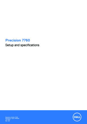
Introduction – PowerGrip GT 3 Belt DrivesPowerGrip GT 3 Belts are anadvanced design of Gates HTD system and feature: a modified curvilinear belt tooth profile withmating sprocket groove. registration and indexing accuracy equivalent tothe conventional PowerGrip Timing Belt System.PowerGrip GT 3 BeltTooth/Groove Contact a higher load-carrying capacity and longer beltlife than either PowerGrip HTD or Timing belts.It’s difficult to make a true quantitative comparisonbetween the backlash of a trapezoidal toothdrive and PowerGrip GT 3 tooth drive due tothe difference in “sprocket to belt tooth” fit. (Seeillustrations at left). Trapezoidal belts contact thesprocket in the root radius — upper flank areaonly, while the PowerGrip GT 3 system permitsfull flank contact.PowerGrip HTD BeltTooth/Groove ContactPowerGrip Timing BeltTooth/Groove ContactThe main stress line in a trapezoidal tooth timingbelt is at the tooth base. During operation stressgreatly reduces belt life. The PowerGrip GT 3system overcomes this with complete tooth flankcontact which eliminates the tooth stress linearea. This greatly increases belt life and preventstooth distortion caused by drive torque. In addition,the conventional timing belt has a chordal effectas it wraps small sprockets. This is significantlyreduced in the PowerGrip GT 3 system due tofull tooth support along the sprocket. Full supportimproves meshing, reduces vibration and minimizestooth deformation.On drives using a low installation tension, smallpulleys, and light loads, the backlash of thePowerGrip GT 3 system will be slightly better thanthe trapezoidal timing belt system. However, withincreased tension and/or loads and/or sprocketsizes, the performance of the PowerGrip GT 3system becomes significantly better than thetrapezoidal timing belt system.2 www.gates.com/drivedesignHTD was developed for high torque driveapplications, but is not acceptable for mostprecision indexing or registration applications.The HTD design requires substantial belt tooth tosprocket groove clearance (backlash) to perform.As smaller diameter sprockets are used, theclearance required to operate properly is increased.HTD drive clearance, using small diametersprockets, is approximately four times greater thanan equivalent timing belt drive.The PowerGrip GT 3 deep tooth profileprovides i ncreased contact area and improves resistanceto ratcheting. e asy, clean entering and exiting the sprocketgrooves resulting in reduced vibration. p arallel contact with the groove and eliminatesstress concentrations and tooth deformationunder load. i mproved registration characteristics andmaintains high torque carrying capability.
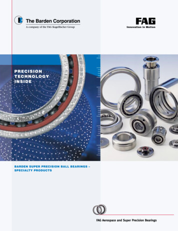
Introduction – PowerGrip GT 3 Belt DrivesThis PowerGrip GT 3 synchronous beltfits in tight, hard to fit applications withroom to spare.Lasts longer than competitive beltsPowerGrip GT 3 belts outlast the competition inthese ways: D eep tooth profile provides superior loadcarrying strength and reduces ratchetingwhen using Gates sprockets. A durable nylon fabric tooth coveringincreases tooth strength and provides wearand abrasion resistance. F iberglass tensile cords wrapped in a durableneoprene body provide flexibility and increaseservice life.When precision is critical, depend onPowerGrip GT 3 beltsPowerGrip GT 3 belts are designed for precisionapplications. Custom-built constructions areavailable for applications requiring maximumperformance. Worldwide manufacturingcapabilities assure you of prompt service forimportant markets.PowerGrip GT 3 belts are available in 2mm,3mm and 5mm pitches. Larger 8mm and 14mmpitch belts are also available. See Catalog 17195 PowerGrip GT 3 Belt Drive Design Manual. 2MGT3MGT5MGT PowerGrip GT 3 BeltProfiles/PitchesHere are some of the many PowerGrip GT 3 belt applications: data storage equipment machine toolsPrecision registrationPowerGrip GT 3 belts provide timing andsynchronization accuracy for flawless registration,with no loss of torque carrying capability. hand power tools postage handling equipment DC stepper/servo applications food processors centrifugesIncreases load-carrying capacity printersLoad capacities exceed HTD and trapezoidalbelt capabilities making PowerGrip GT 3 thechoice for accurate registration, heavy loads andsmall sprockets. Smaller and tougher than HTDor trapezoidal belts, PowerGrip GT 3 belts giveengineers more space-saving flexibility formicro-technology. floor care equipment money handling equipment medical diagnostic equipment sewing machines automated teller machines ticket dispensersSounds this quiet plottersPowerGrip GT 3 belt’s specially engineered teethreduce noise and vibration. Clean meshing andreduced belt width results in noise reduction whencompared to PowerGrip Timing and HTD belts. copiers robotics equipment vending equipment vacuum cleaners office equipmentPowerGrip GT 3 Belt DrivesPages 13-35 www.gates.com/drivedesign3
Introduction – PowerGrip HTD Belt Drives3mm5mmPowerGrip HTD BeltProfiles/PitchesGood torque carrying capability anddesign versatilitySome PowerGrip HTD BeltApplications are:PowerGrip HTD drives provide advantages overconventional gear and chain type drives f loor polishers s ewing machinesrun quietdo not need lubricatingrequire virtually zero maintenancehigh reliability and low operating costsGates 3mm and 5mm pitch HTD belts are capableof operating at both low and high speeds whilecarrying heavy loads. They can provide higherspeed ratios than comparable XL and L pitch timingbelts in the same space. Compared to conventionaltiming belts, they transmit the same power in amore compact drive package.HTD belts have the same characteristics aslarger 8mm and 14mm pitch belts, but aredesigned for smaller horsepower and higher speedrequirements. v acuum cleaners s anders o ffice equipment p laners c entrifuges d iagnostic equipment p ower tools v ending machines j uicersPowerGrip HTD Drives. Pages 36-453mm and 5mm pitch HTD belts provide positivenon-slip power transmission with many advantagesover conventional drive systems. They can handletough applications, even those subject to suddenshock and overloading.PowerGrip Timing Belt DrivesMXLXLPowerGrip Timing BeltProfiles/Pitches Provide positive, non-slip powertransmissionPowerGrip Timing BeltsApplication Types:PowerGrip Timing Belts are a good standard lineproduct with a history of reliability. Around forover 60 years, this product line was the flagshipof synchronous power transmission prior to Gatesintroduction of PowerGrip HTD and GT Belts. o ffice equipmentGates timing belts are made with a true designpitch, a standard of the Rubber ManufacturersAssociation and the International StandardsOrganization. r obotics m oney handling equipment f ood processors m edical equipment d ata processing equipment m iniaturized applications m ailing equipment p rinters/plottersPowerGrip Timing Drives Pages . 46-504 www.gates.com/drivedesign
Introduction – PowerGrip Twin Power Belt DrivesDual driving surfaces allow for unique,problem solving drive designs0.200’’ (1/5’’) pitch extra light (XL)PowerGrip Twin Power Timing BeltProfile/Pitch3mm5mmPowerGrip Twin Power HTD Timing BeltProfile/PitchGates Twin Power Belts have teeth on both sides toprovide synchronization from both driving surfaces.This feature makes possible drive designs such asmulti-point drives, rotation reversal with one belt,serpentine drives, etc. Twin Power belts providesolutions to difficult design problems.Twin Power Belts are similar in constructionto regular synchronous belts, including nylonfaced teeth on both sides. This constructionuses essentially the same design parameters asstandard synchronous belts. They are rated atthe same horsepower capacity as conventionalPowerGrip Belts of identical pitch and width oneither side of the belt.NOTE: Twin Power Belts are available in GT2, HTDand Timing Belt configurations, so designers canuse them in a wide variety of applications.Some typical PowerGrip Twin Powerapplications are: c opiers s erpentine drives r eversing rotationsPowerGrip GT2 Twin Power Belts.Pages 22-23PowerGrip HTD Twin Power Belts.Pages 42-43PowerGrip Twin Power Belts.Pages 51-523mm5mmPowerGrip Twin Power GT2 Timing BeltProfile/PitchPowerGrip Long Length BeltingFor drives that require belt lengths longerthan can be produced in the conventionalendless formTypical PowerGrip Long Length Beltinguses are:PowerGrip Long-length Belting has the same basicconstruction as conventional Gates timing belts.Gates can make continuous belting in spiral cutform on a made-to-order basis. r ack and pinion drivesFor information or assistance on any long lengthbelt problem, contact Gates Product ApplicationEngineering.PowerGrip Long Length Belting.Page 54 www.gates.com/drivedesign r eciprocating carriage drives l arge plottersClamp Plate Specifications.Page 555
Introduction – Polyflex JB Belt Drives1/8”3mm3mm3/16”5mmStandard Polyflex Belt Profile65mmPolyflex JB BeltProfileGates Polyflex JB is a joinedbelt with a different angleTypical Polyflex JB applications are:“High Power Density” is what you get from thishigh-precision belt. Developed by Gates andproduced using patented manufacturing processes,Polyflex JB belts provide load-carrying capacity athigher speeds on precision applications. Polyflex JBbelts can operate at shaft speeds well in excess of10,000 rpm. b ench-type milling machinesPolyflex JB features joined belt construction forstability. Backside ribs relieve bending stress onsmall sheaves and provide lateral rigidity. The 60 angle provides more undercord support to thetensile section and distributes the load evenly. h orizontal milling machinesThe small cross-section allows belts to be usedon short centers and small diameter sheaves for“cleaner” machine designs. It virtually eliminatesthe need for double-reduction drives and lets youuse more cost-effective single-reduction drives. d rilling machinesGates Polyflex JB belts are a homogenousproduct. State-of-the-art manufacturingprocesses assure uniformity of construction,resulting in minimal vibration and smoothoperation on precision applications. c entrifugesGates special high modulus polyurethanecompound has a high coefficient of friction thatresists fatigue, wear, ozone and most adverseenvironmental conditions. f ansCost Savings — PLUS! Polyflex JB belts bringV-belt economy and simplicity to applicationswhere conventional V-belts are not feasible,resulting in cost savings and design freedomnever before possible.Polyflex JB Drives Pages. 77-81 www.gates.com/drivedesign c omputer peripherals g lass blowing lathes v alve grinding machines c rankshaft grinding machines w oodworking spindle drives d ental grinders f loor care equipment m icrofiche readers l athe drives k nife grinders s cissor sharpeners b lowers w heelchairs o ptical lens grinders m etalworking spindle drivesFor additional Polyflex belt data refer to GatesHeavy Duty V-Belt Drive Design Manual #14995-A
Introduction – Micro-V Belt DrivesH sectionJ sectionMicro-V Belt ProfilesFor the best ribs around, look nofurther than Gates Micro-V BeltsTruncated tooth profile increases flexibilityand reduces heatGates Micro-V Belts outperform other V-ribbedbelts because the Vees are shorter. The truncated(shortened) profile of the Vees give Gates Micro-VBelts increased flexibility, reduced heat buildup andlets them perform at extra high speeds on smallerdiameter sheaves.Just some of the applications for Micro-VBelts are: h igh speed machine tools m illing lathes w ashing machines p recision surface grinders f loor polishers t ool grinders h igh-speed printing pressesGates exclusive truncated designgives you c entrifuges 80% higher horsepower capacity than RMAstandards. p recision center lathes extra load-carrying capacity for extra long life. Truncated belt ribs for improved wedging in thepulley grooves and greater load capacity.Micro-V Belts are smooth running and resistantto oil, heat and other adverse conditions. Plus,undercords are static conductive. a gitators p umps h igh-speed atomizers t rash compactors p laners and molders d ryers f ood slicers e lectric massagers l awn mowers j uice mixers i ndustrial vacuum cleaners m icrowave ovens b akery equipment c ompressors f ansMicro-V Drives Pages. 82-83For additional Micro-V belt data refer to GatesHeavy Duty V-Belt Drive Design Manual 14995-A. www.gates.com/drivedesign7
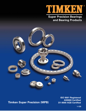
Drive Comparison GraphsThe following graph contains a representation of horsepower ratings, over a wide speed range,of the belt types represented in this catalog. The sprocket/pulley/sheave diameters and beltwidths are all comparable for a realistic comparison of product capability.The following graph provides a comparison of the rated torque carrying capabilities ofsynchronous belts, on small diameter sprockets/pulleys at low speeds. The sprocket/ pulleydiameters and belt widths are all comparable for a realistic comparison.Low Speed Drive Rating GraphComparable Diameters & Widths0.60Rated 100200300400500600Speed (RPM)8 www.gates.com/drivedesign800 1000
Synchronous Drive ComparisonsDesigners and engineers find that PowerGrip beltdrives provide exceptional versatility and reliability.Small and lighter weight drive packages can beused in a wide variety of applications. PowerGripdrives also offer efficient operation over a widerange of loads and speeds.Drive Package ComparisonCompact, space saving belt drives canbe designed with high-performance drivesystems like PowerGrip GT 3. As illustrated,PowerGrip GT 3 drives are significantlynarrower than comparably designedPowerGrip HTD and PowerGrip Timing Beltdrives, resulting in space, weight and costsavings.3mm PowerGrip GT 3 Belt Drive – 6mmDriveR: 3MR-30S-06 (1.128” P.D.)DriveN: 3MR-30S-06 (1.128” P.D.)Belt Width: 6mm3mm PowerGrip HTD Belt Drive – 15mmDriveR: P30-3M-15 (1.128” P.D.)DriveN: P30-3M-15 (1.128” P.D.)Belt Width: 15mmXL PowerGrip Timing Belt Drive – 31.75mmDriveR: 18XL125 (1.146” P.D.)DriveN: 18XL125 (1.146” P.D.)Belt Width: 1.25” (31.75mm) www.gates.com/drivedesign9
Synchronous Drive Comparisons – continuedThe development of the PowerGrip GT 3 belthas produced an impressive range of enhancedproperties and subsequent design opportunitiesfor engineers.The following comparative studies have beenincluded to allow designers to make quantitativeassessments and to highlight the most significantimprovements and design opportunities.Particularly significant points from the followingcomparative studies are:DurabilityThe greatly increased durability of the PowerGrip GT 3 design has resulted in power capacitiesfar above those quoted for similar size belts. Theresulting small drive packages will increase designflexibility, space utilization and cost effectiveness.Tooth Jump ResistanceThe very significant improvement in tooth jumpresistance of PowerGrip GT 3 when compared tosimilar belts has several important advantages.a. Ratcheting resistance during high start-up torques.b. Reduced bearing loads, particularly in fixedcenter drives. Lower average tensions can be usedwithout encountering tooth jump at the low-tensionend of the tolerance ranges.c. Reduced system losses result from lower pretensioning, with less potential for tooth jumping.a10 www.gates.com/drivedesign
Synchronous Drive Comparisons – continuedNoiseThe smoother meshing action of thePowerGrip GT 3 belt, with its optimizeddesign produces significantly lowernoise levels when compared with other,similar sized belt types operating undersimilar speeds and tensions. Theseimprovements are enhanced by thefact that narrower belts can be useddue to increased power capacities.--Positioning AccuracyThe PowerGrip HTD belt tooth formswere primarily designed to transmithigh torque loads. This requirementincreased tooth to groove clearanceswhich resulted in increased backlashwhen compared with the originalclassical designs.PowerGrip GT 3 has reversed thiswith power capacities now exceedingthose of PowerGrip HTD while givingequivalent or higher levels of positionalaccuracy than PowerGrip Timing belts. www.gates.com/drivedesign11
PowerGrip GT 3, HTD and Timing BeltDrive Selection Procedure – single sidedStep 1. Determine design load.Service factors between 1.5 and 2.0 are generallyrecommended when designing small pitchsynchronous drives. Knowledge of drive loadingcharacteristics should influence the actual valueselected. A higher service factor should be selectedfor applications with high peak loads, high operatingspeeds, unusually severe operating conditions, etc.Lower service factors can be used when the loadingis smooth, well defined, etc. and the reliability is lesscritical. Some designs may require service factorsoutside the 1.5 to 2.0 range, depending upon thenature of the application. Contact Gates ProductApplication Engineering for additional information.Stall torque of the driveR, or peak torque of thedriveN unit, may be part of the nameplate data. Ifnot, calculate Torque (Q) by using these formulas:D. Check the Belt Speed, V, of the smaller sprocketselected, using the following formula:V (fpm) 0.262 x Sprocket PD (in) x Sprocket RPMV (m/s) 0.0000524 x Sprocket PD (mm) x Sprocket RPMand,m/s 0.00508 x fpmNOTE: Belt speeds in excess of 6,500 fpm (33.02m/s) require special sprocket materials and dynamicbalancing.Step 3. Determine belt length and nominalcenter distance.A. Using the allowable range of center distancesrequired by the drive design, calculate the beltPitch Length (PL) using the following formula:PL 2CD [1.57 x (PD pd)] Q (lb - in) 63,025 x Shaft HP ,Shaft RPMQ (lb - in) 8.85 x Q (N - m) orQ (oz - in) 16 x Q (lb - in)Peak Design Load Load x Service FactorNOTE: When performing drive calculationsbased upon torque loads, drive input/outputpower is constant but drive input/output torqueis not. Drive input/output torque is a functionof the speed ratio. Drive designs should bebased upon the smaller, faster sprocket, atthe torque load calculated for its operatingspeed. These critical drive parameters shouldbe used for all engineering calculations. Seeengineering calculations on Page 103 foradditional formulas and unit conversions.Step 2. Determine belt pitch and selectsprockets.A. Select Belt Pitch by using the Belt PitchSelection Guide on pages 25, 41 and 53.B. Determine the speed ratio by dividing the largerspeed, Sprocket Pitch Diameter or SprocketGroove Number by the lesser speed, SprocketPitch Diameter or Sprocket Groove Number.C. Refer to the appropriate Sprocket DiameterTables on pages 29-31, pages 46-49 orpage 57-58. Select sprockets based uponspeed ratio and drive requirements. Use stocksprocket sizes whenever possible.12(PD - pd)24CDWhere CD Drive center distance (in)PD Large pitch diameter (in)pd Small pitch diameter (in)Using the calculated range of pitch lengths,select a belt of the proper length from theappropriate belt length table. Use a standardlength as shown in the tables on pages 15-16,pages 39-40 or pages 51-52, if possible.B. T he approximate nominal center distance forthe drive can be calculated using thefollowing formula:Center distance K K 2 - 32 (PD - pd)216Where K 4PL - 6.28 (PD pd)PD Large pitch diameter (in)pd Small pitch diameter (in)PL Belt pitch length (in)See Engineering calculations on page 103 orcontact Gates Product Application Engineeringfor accuracy within 0.001”.Step 4. Determine belt width.Belt Width Selection Tables on pages 18-21, pages42-43 and page 54 show the load ratings for thestock widths of each of the stock belt pitches.Using the smaller sprocket groove number andrpm as determined in Step 2, locate a torque orhorsepower rating in the Belt Width Selection www.gates.com/drivedesignTables of the proper belt pitch nearest to, butgreater than, the peak design load from Step1. Torque or horsepower ratings for various beltwidths can be calculated by multiplying the tablerating by the appropriate belt width
problem solving drive designs Gates Twin Power Belts have teeth on both sides to provide synchronization from both driving surfaces. This feature makes possible drive designs such as multi-point drives, rotation reversal with one belt, serpentine drives, etc. Twin Power belts provide solutions to difficult design problems.