Transcription
H 6,6 "1.1.2'J.x 60065308tACCESSIOP(NUMBER)o/'/f43 OBIAL PROFILE OFLAMINAR FLOW CLEAN ROOMSSEPTEMBER19651GPOPRICECFST PRICE(S) /.Hard copy (HC)Microficheff653July(MF)./? / 7," / " -' NDJ
IX-600-65-308i'iLAMINARFLOW PROFILECLEANMICROBIAL""iROOMSOF: EdmundM. Powers,Laboratoryfor AtmosphericSpace BiologyBranchand BiologicalSciencesISeptember" M.S.Goddard1965Greenbelt,Space FlightMd.Center
!MICROBIAL PROFILE OF-LAMINAR FLOW CLEAN ROOMSbyEdmundM. Powers,M.S.Space Biology BranchLaboratory for Atmosphericand Biological SciencesSUMMARYThe microbial contamination in the air and on surfaces of spacecraft andtable tops during exposure in laminar downflow and crossflow rooms was evaluated. The concentration of viable particles was extremely low and well withinthe requirements specified by NASA.The concentration of viable particles in the air of the two rooms over a: 4-hour period was a maximum of 0.04 viable particles/ft 3 of air in the occupied: d0wnflow room and 0,5 viable particles/ft 3 of air in the occupied crossflowroom. The NASA standard for air of bioclean rooms is 2.0 viable particles/ft 3.The counts were approximately the same in the air of both clean rooms whenthe rooms were unoccupied and the airflow was on. Personnel did not appear to. contribute significantly to the microbial contamination in the air of the downflowroom, but counts were increased significantly by personnel in the crossflow roomboth upstream and downstream of the sampling devices.The level of contamination in the air downstream of personnel was not significantlyhigher than theair upstream of personnel in the crossflow room.The viable contamination on the surface of the nosecone, landing capsule,and table top was measured by the Rodac impression technique.Counts on thesesurfacvs ranged from 0 to 23 viable particles/ft2 in the downflow room and from0 to 58 viable particles/ft2 in the crossflow room. The viable contaminationonall three surfaces over a 4-hour period did not appear to be significantly increased when personnel were introduced into the downflow room, but in the crossflow room, counts on these same surfaces were increased by the presence ofpersonnel, particularlywhen persounel worked upstream of them.Handling of a landing capsule with gloved hands did not significantlyincreasethe microbial contamination on its surface in either clean room. This resultindicates that the use of sterile clothing, including gloves, and proper handlingprocedurestogether with a laminar airflow could reduce microbial contaminationconsiderably.The efficiency of the laminar flow room in providing clean air and the extremely low counts obtained, particularly in the downflow room, have considerableiiiLL]
:significance for spacecraft assembly and sterilization.By reducing contam .nation to a minimum, sterilization times might be reduced and sterilization procedures made less harsh. The small degree of contamination obtained in laminarflow clean rooms might also insure that our ste rilization procedures are effective.d.Jiiv
I1!1liiITABLEOF CONTENTSittPageJ ,SUMMARY .inlINTRODUCTION1"MATERIALS:5AND METHODS .Laminar Downflow Clean Room .Laminar Crossflow Clean Room .Mars Spacecraft .Air Sampling .Surface Sampling .Stainless Steel Table .Microbial Fallout .MediaClothing .Sampling Procedure.Statistical Analysis., .RESULTS-3: . .Level of Microbial Contamination in the Air of the LaminarDownflow Room. . .Level of Microbial Contamination in theAir of the LaminarCrossflow Room . .Level of Microbial Contamination on the Surface of the NoseconeWhile Exposed in the Laminar Downflow Room .Level of Microbial Contamination on the Surface ofthe NoseconeWhile Exposed in the Laminar CrossflowRoom ., .Level of Microbial Contaminationon the Surface of the MarsLanding Capsule While Exposed in a Laminar Downflow Room .Level of Microbial Contamination on the Surface of the MarsLanding Capsule While Exposed in a Laminar Crossflow Room .Level of Microbial Contamination on the Surface of a Staivless3:3478888 91010ii111213141617Steel Table While Exposed in a Laminar Downflow Room .Level of Microbial Contamination on the Surface of a Stainless19SteelTableWhile Exposed ina Laminar CrossflowRoom .MicrobialFalloutina Laminar Downflow Room .Microbial Fa Uout in a Lain inar C rossflow Re 0 m .202123V5,[*;
TABLEOF atical :{CalculationsLevelsof ConNrm.'.'nationflow RoomsREFERENCES27in LaminarsaCross-. . : .392.,rand Laminar302!DownflowJ
LIST OFILLUSTRATIONSFigure:12Mars Landing Capsule Configuration.Protective Nosecone Configuration .346Photograph of Mars Landing Capsule and ProtectiveNoseconeLevel of Contamination of the Air in a Laminar DownflowRoom .Level of Contamination of the Air in a Laminar CrossflowRoom .Level of Contaminationon the Surfaceof a NoseeoneWhile7Exposedin a LaminarDownflow Room .Level of Contaminationon the Surfaceof a Nosecone56121314While10Table While ExposedLevel of ContaminationDownflow Room .of a in a Laminaron the Surfacein a LaminarMicrobialFallouton Blood AgarRoom .PlatesMicrobialFallout on Blood AgarRoom .PlatesbIi!.159:55Exposed in a Laminar Crossflow Room .Level of Contamination on the Surface of a Landing Capsuleile Exposed in a Laminar Downflow Roora .Level of Contaminationon the Surfaceof a Landing CapsuleWhile Exposedin a LaminarCrossflowRoom .Level of Contaminationon the Surfaceof a StainlessSteel8:PageviiRoom .in a Laminar1618Downflow22in a LaminarCrossflow23
MICROBIAL PROFILE OFLAMINAR FLOW CLEAN ROOMSbyEdmund M. Powers,M.S.Space Biology BranchLaboratory for Atmosphericand Biological Sciences.- : :INTRODUCTION"The microbial profile of two types of lami,mr flow clean rooms was evaluated by Goddard Space Flight Center in cooperation with the Sandia Corporation,contractor for the U.S. Atomic Energy Commission, Albuquerque, New Mexico.A search of the literature reveals that very little is known about ti,e viable:microbial contamination in r!ean rooms, particularlythat in laminar flew cleanrooms. The use of clean rooms for spacecraft assembly makes it essential toknow what levels of microbial contaminationcan be expected under vari i g working conditions and to set limits for the viable contaminationof air and surfacesin clean rooms,j". ; '.:-"- , :.,I, Hobby estimated (ref, 1) that the microbial population f the surface of aspacecraf is in he order of 109 microorganismsper 100 square feet. Calculations shewed that 22.1 hours at 135 C would be required to red ,ce the population so that there would be ' chance in 10,000 of a single crganism surviving.therefore,to achieve a probabilityof not more than 1 chance in 10,000 of landinga viable particle on a planet, microbial contamination on the spacecraftmust beheld at the lowest possible level so that an acceptable degree of confidence in theeffectivenessof the terminal heat sterilizationcycle is obtained (ref. 1). Contamination control proceduresmus be established,improved upon, and closelymonitored to verify their adequacy.Assembiy operations during assembly andtest of actual flight hardware must also be extensively monitored.Because these monitoring .rocedures Vary considerablyamong investigators,a great need exists to standardizethem so that results of clean rooms may becompared and so that some meaqure of confidence in clea , rooms in variousparts of the country may be obtah ed.The methods commonly used for sampling air include impaction on solidmedia {settling prates and strips} and impingement ill liquid media. Surfaces areusually sampled with swabs or contact (Rodac} plates.Goddard (ref. 2) listedthe advantages and disadvantagesof several methods used for sampling air andsurfaces and proposed an excellent method for sampling the micro*,ial eontamination of surfaces using Rodac plates.1,"
Danieletal. (ref. 1), who developed criteria for an assembly, test, and sterilization facility for Jet Propulsion Laboratory. (JPL), compared air sterilizationequipment and concluded that a combination of air filtration and air ,ashingoffered the most economical and effective arrangement to meet basic air cleanliness requirements.In this connection, the Whitfield (refs. 3 and 4) laminarir flow system offered excellent possibilitiesfor the assembly of spacecraftand for a clean room and steriliz, .tion facility.The laminar air flow sy3tem when in combhuation with adequate air filteringsystems has great potential for increasing clean-room standards of cleanlinessby several ordcrs of magnitude. The laminar concept developed by Sandia Corporation (ref. 3) dses a single pass technique in which one wall or ceiling consists ofof a compb te bank of high-efficiencyparticulate air (HEPA) filters.These filters collect 99.97 percent of all contamination 0.3 micron in size and larger before it enters the clean room, Because of their resistance these filters tend tocreate a uniform air flow throughout the room.The opposite wail or gratedfloor is designed as a complete return air plenum; the air makes a single passacross the room either in a horizontal (laminar crossflow room) or downward(laminar downflow room) flow pattern. The laminar flow technique is designedfor as high as 800 air changes per hour while the conventional type clean roomis normally designed for only 20 air changes per hour (ref. 5).Daniel et al. (ref. 1) evaluated both laminar dog, low and laminar crossflowsystems and concluded that the laminar downflow system offered the best solution for the design of an ultraclean facility.Economically,the per unit cost of alaminar crossflow roow may be less than the cost of a laminar downflow room,all factors being equal; however, by decreasing the air velocity to a permissablelevel and increasing the size of the room, the per unit cost of the laminar downriow concept should approach tt,e cost of a comparable laminpr crossflow installation sh ce the amount of equipment and number of personnel.can be increased,reducing the unit cost per square foot of working space.4 "':,Portner (ref. 6) studied the level of microbial contvanination in a MartinCompany clean room (conventional type) over a 52-week period. She found thatthe number of microorganismsper cubic foot of air was about 10 times greaterin the iactory than in the clean room and that aerobes appeared to be more prominent than anverobes.She also reported that the microbial contamination on astainless steel surface due to aerial fallout rapidly reached a maximum leveland remainedmore or lessconstantthroughouttheyear. This studyalsopointsout the need for clean room facilities.The present study was undertaken to determinethe microbialcontaminationintheairand on surfacesinlaminardownflowand laminarorossflowrooms.
iBecause of its configuration,ivehicle and its protective nosecoite were also monitored to determine the microbial contamination on its surface during exposure in flJese laminar flow cleanrooms. The results, here reported, indicated that the laminar flow clean roomis extremely effective in controlling .microbiological contamination and that thissystem far surpasses existing requirements for bioclean room facilities.Theuse of the laminar do , flow room for spacecraft assembly has great potentialand should be seriously considered. a full scale conceptual model of a planetary landerMATERIALS AND METHODSLaminar Downflow Clean RoomThe clean room in which these tests were performed is located at SandiaCorporation in Albuquerque, New Mexico, and is composed of three separaterooms connectedto form a single unit. Each end room is approximately 8 ftby : 0It. The center section, in - hichall experiments were performed, isapproximately 10 ft. by 20 ft. Each of the three sections has its own air-handling/air-conditioningunit; 4-foot sliding doors at the center of each end of each unitprovide free access through the entire test area. The ceding of each roomconsists of fiberglass high-efficient,particulate air (HEPA) filters throughwhich air enters. Fluorescent lights having little air resistance run the lengthof the room. The floor is a standard, heavy-duty bar-grating through which theair exits from the room. All sections are constructed of stainless steel tofacilitate cleaning (rcf. 7).The air flows vertically downward throdgh the entire ceiling at 100 linearft per minute in the main room (approximately 800 air changes per hour). Temperature was controlled at 700(; 2 and humidi to 30 10 percent. All filtersand filter mountings were checked thoroughly for penetration using smoke, andall leaks were sealed. Subsequent tests for airborne particulate contaminationwith a Royco particle counter (PC-200-A) confirmed that there was zero penetration of the filters by smoke particles (size range averaging about 0.25 micron).Airborne particle count (0.3 micron and larger size# was zero throughout theroom, providing there was no particle generation between the filter and thecounter (ref. 7).:Before this study began the room was vacuumed and all surfaceswashed with a mild detergent.Laminar CrossflowwereClean RoomThe clean room in which this study was performed is located at the GultonIndustries, Albuquerque, New Mexico. The air flow of the cr( ssflow room differs3
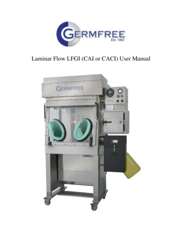
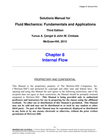
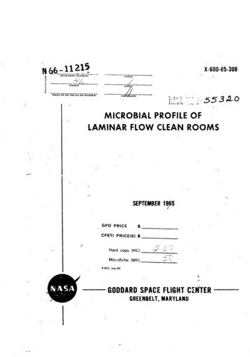
somewhat from the air flow of the downflow room in that it is directed horizontally across the room from one wall to the opposite wall. The two walls consistof filter banks, with rough prefilters in the wall at the air-exhaust end of theroom, and final absolute filters in the opposite wall at the air-input end of theroom. The absolute filters are fiberglass high-efficiencyparticulate air (HEPA)filters, which filtered out all particles 0.3 micron and larger from air enteringthe room. The remaining two wails and ceiling are of dry wall construction andpainted with vinyl paint. The floor i solid and covered with vinyl tile.This room meets the specifications of Federal Standard 209 (ref. 8) forparticulate matter and is rated as class 100 at the air-input end and class 10,000or better at the a r-exhaust end of the room, The dimensions of the room are33 ft wide, 96 ft long, and 9 ft high Because of the length of the crossflow room,the rate of airflow was 130 ft per minute. Temperature was controlled at 22 C 2 and humidity to 35 percent.Tests for leaks in the filters and filter mountings and for airborne particulate contamination were conducted about 6 months before this study was initiated.These tests were performed by the same methods used in the downflow room.This crossflow room is used by the Gulton Indnstrles for the assembly ofelectronic circuits and is routinely occupied by 20 women and 3 to 5 men. Theentrance and exit to the room is located at the exhaust end.Mars SpacecraftFigures 1 and 2 show the general configuration of the Mars landing capsuleand the protective nose cone respectively.Figure 3 is a photograph of the landhag capsule and nose cone as they appeared in the clean room during the sampiing prodedure. The capsule is 23 inches long by 15 inches high; the noseconehas a diameter of 16-1/2 inches and is 27 inches long. A technical descriptionof the spacecraft can be found in the Planetary Project Document (ref. 9). JThe nosecone and capsule were placed side by side on a grated table 12 incheshigh to permit easy access to the interior of the cone (Figure 3). The noseconewas divided into four parts: the ex rior aluminum surface into two equal halvesand the interior fib rgla.qs surface into two equal halves. Each of the four partswas gridded to form 2B lual squares. The grid intersectionswere numbered1 through 16 in a serpentine fashion; at each sampling sequence, 32 Rodac impression samples of the cone were taken by sampling the 8 odd (red) intersections of each of the four parts at one sampling sequence and the even (black)intersectionsat the next sampling sequence.
:igure2, p otectiveNoseCOneC nfigu oti n19660Cf-
.,.,o -.o"-"" o': -,."'S':,-.4 I--,.': 'T' : ,"lb,,.')'-/'. ":.Ti:. ', , '-'-[ !"--". ,,lm .-. ." -I:'",,.,",, :Figure3. no:.-,"The landing capsule, which was not gridded, was placed on the table withthe metal surface up. Th bottom of the capsule was covered by a trussgridshock-absorbingmaterial, which was not sampled for microbial contamina-:fion. Rodac impression samples of the capsule were taken from the fiat metalstraps which surround the capsule and serve as upright mechanisms when6
[released and from the flat surface at one end and on top of the capsuleTen Rodac samples were taken at each sampling sequence.:(Figure ; ).In the downflow room the spacecraft were placed in the center of the room.In the crossflow room the spacecraftwere placed dox streamof personnel andapproximately10 it in front of the air outlet for one sampling sequence and upstream of personnel and approximately6 ft in front of the air supplyfor the next;when the room was unoccupied, the spacecraftwerc placed in the center of the room.The cone and the capsule were decontaminatedwith 80 percent isopropylalcohol 10 to 15 minutes before the first surface samples were taken at zerohour.Air SamplingAndersen samplers (ref. 10}, which are six-stage sieve type samplers, wereused to collect viable airborne particlesin the clean rooms.Each stage conrains a perforated plate with 400 holes immediatelybelow which was a plate ofTr 2aticase Soy Agar (BBL).Four Andersen samplers were employed simultaneouslyfor each samplingsequence.They were positioned in the downflow room as follows: (1) in front ofthe entrance, 3 ft above the floor; (2) m the middle of the room, approximately2 ft from the spacecraftand 7 ft above the floor {1 ft below the air supply); (3)on the grated table next to the landing capsule; (4) at the far end of the room,1 ft above the floor.In the erossflow room, three of the Andersen samplers were placed atbenchtop level and one was placed on the grated table with the spacecraft.Allsamplers were placed so that they were downstreamof all workers for onesampling sequence and upstream for the next sampling sequence.When theroom was unoccupied, the samplers were positioned around the spacecraft inthe center of the room.Each sampler was sterilized by wrapping in paper and autoclaving at 121 Cand 15 lbs pressure for 30 minutes.Petri plates were wiped with 80 percentisopropyl alcohol and allowed to dry before being loaded into the Andersensampler.Air was drawn through the samplers with 1/6-hp vacu n1 cubic foot per r,dn (cfm) for 15 minutes.Flowmeterswerethe airflow through each device before sampling.The vacuumplaced on the floor so that any fumes that mi&ht have escapedcarried out of the room by the airstream.pumps at a rate ofused to measurepumps werewere immediately
Continuousand uninterruptedsamplingofthe iableparticlesper unitvolume ofairwas accomplishedwithan Anderseu 0800Monitorforairbornebacteria(ref.11). This deviceconsistsoian agar-coateddrum, 5-1/2inchesindiameterby 3-5/8 incheshigh,mounted on a threadedshaftina 3-1/2 quartstainlesssteelbeaker. The drum isrotatedby a Crarnerti r mounted on thecover. A jetfor impactingairborneparticleson thedrum is mounted inthesideofthebeaker. A stainlesssteeljetcalibratedtodeliver3 litersof airper minutewas employed and theflowratewas adjustedwitha flowmetertothespecifiedflowrateofthejet.The 0800 Monitorwas placedon thegratedtablenexttothenosecone. The beakerwas cleanedand use.SurfaceSamplingRodac platesdevelopedby I{a11and Hartnett(ref.12)were used todeterminethelevelofmicrobialcontaminationon surfaces(spacecraftand stainlesssteeltable)inthecleanroom. Each platewas filledwith15.5to16.0ml ofagarmedium toform icnsoftheagarontoa surface.Sampleswere takenbyimpressingtheagardirectlyon thesurfacetobesampled.Plateswere tainlessSteelTableA stainlesssteeltable6 ftlongby 3-1/2R highby 3 ftwide was placednexttothespacecraftinbothcleanrooms. The tabletopwas griddedinthesamemanner as thenosecone,i.e.into25 equalsquares. The intersectionswere rnbered 1 through16 ina serpentinefashion.The odd and even intersections(8each)were sampled on alternatesamplingperiodsby theRodac was determinedby exposingcommerciallypurchasedbloodagar plates(BBL) inthreedifferentareas oftheroom atbench-toplevel. Fiveplateswel exposedineach area for2- and 4-hrperiodsduringeachsamplingMedmTrypticaseSoyAgar (BBL) was used forallsamplingprocedures. Mediawas dispensedwithan automaticpipettingmachine intoglasspetridishes(fortheAmler n samplers)in27-mi volumes and intoRodac platesin15.5-mivolumes. The gar drums in the 0800 Monitor received approximately 260 ml of8
agar medium. All plates and agar drums were incubated at 35 C for 48 hrs priorto use to determine their sterility and to dry them sufficiently for sampling.Clothing:The investigator who collected the samples wore sterile clothing consistingof cotton cap, face mask, surgical gown. and sterile rubber gloves. The clothingwas donned j,kst before entering the room. Personnel who occupied the downflowroom for 2- and 4-hr periods wore only a surgical gown and personnel who ocLcupied the crossflow room wore only a smock and booties.Sampling ProcedureThe down/low room and the nosecone, capsule, and stainlessthe room were monitored under the three following conditions:steel table in Airflow turned off and room unoccupied Airflow turned on and room unoccupied Airflow turned on and room occupied by two workersWhen the rcom was unoccupied, the sampling sequence was at 0, 2, 4, 6, and 23hr. Because the room was occupied for a maximum of 4 hr, the sampling sequence during occupancy was at 0, 2, and 4 hr.Prior to each sampling sequence, the nosecone, capsule, and stainless steeltable were decontaminatedwith 80 percent isopropyl sJcohol. The first sampleswere collected approximately15 minutes after decontamination(zero hr). Nofurther decontaminationwas made during the sequence.Sterile clothing wasdonned and all materials necessary for sampling were prepared before the roomwas entered.Surface samples were taken by two workers i.mmediately uponentering the room and sampling was accomplishedin less than 5 minutes.TheAndersen samplers were then placed into position and turned on for 15 minutes.The two workers left the room while the Andersen samplers were operating, except of course when the room was sampled under occupied conditions.Sampling conditions differed slightly in the cross[low room because the airsupply could not be turned off. Air and surface samples were taken in the crossflow room under the following conditions: Room occupied and all samples taken upstream of working personnel Room occupied and all samples taken downstream of working personnel Room unoccupied and samples collected midway between the air inletand the air outletDuring occupancy 20 to 25 people (20 women and 3 to 5 men) were in the room atall times. Samples were collected at 0, 2, 4, and 6 hr while the room was occupied and at 0, 2, 4, 6, and 23hr while the room was unoccupied.The 20 to 25Wq,
people who worked in the room assembling electronicfrocks and boots.circuitswore only lint-freeDuring occupancy of both clean rooms, the capsule was sampled by the Rodacimpression method before and af-ter handling with gloved hands. Sampling wasaccomplished by taking ten Rodac samples of the capsule after decontamination,handling of the capsule by two workers, and taking ten more Rodac samples.Both workers rubbed their hands over all sampling surfaces and handed the capsule back and forth to each other several times. The capsule was not decontaminated again after the handling procedure.The two investigators who occupied the downflow room for 2- and 4-hourperiods were completely unrestricted in their movements.They wore only asurgical gown and performed such tasks as counting colonies, loading Andersensamplers, labeling plates, and wiping plates used in the Andersen samplerswith isopropyl alcohol. They walked by the spacecraft and stainlesssteel tableseveral times, leaned over them, and waved their arms over them. They extended their ungloved hands into the interior of the cone without touching it.All labor was performed within 3 or 4 ft of the spacecraft.The same taskswere performed in the crossflow room in addition to the labor that was performed by the 20 to 25 people who routinely worked in the room.StatisticalAnalysisThe 95 percent upper and tower confidencelimitsfor the reported valueswere computed and are indicated in Figures 4 through 13 by the shaded areas foreach bar. These figures are merely graphical representationsof the recordedvalues. For actual values, refer to the tables in the appendix. Where a statementwas made that a difference was, or was not significant, a significance test wasperformed to test the null hypothesis that the reported value was the same underone condition or at one time as under another condition or time.The confidence limits were constructed and the tests performed taking intoaccount the fact that the reported values are coded functions o Poisson variables.By coded is meant the reported value is the product of a constant and acount, which is assumed to follow the Poisson distribution.The estimated standard deviation of the reported value is the product of the constant and the squareroot of the count. The confidence limits on the reported value were developedby multiplying the limits of expectation appropriate to a coun t ,llowing thePoisson distributio,t by the constant. This procedure was followed for countsless thai 0. For counts greater than 50, confidence limits were developed bytreating the reported value as a normally distributed observation with standard deviations as previously described.Approximate significancetests of'10
differencesbetween reported values wer made by again tre,' ting the reportedvalues as normal and applying the standard procedure for testing whether twonormally distributedobservationscame from populations with the same mean.!!When the airflow was off in the dov, flow room (Figure 4A). the v rlationamong She eight counts obtained from the air was substantiallyin excess of thatbased on Poisson considerations.This indicated heterogenicityin the particleidensity throughout the room and from one day to another.Confidence limits inthe mean number of viable particles per cubic foot were calculated in the usualfashion appropriateto a random sample from a nozmal population.(Seeappendix. )iIi;!:i::':iRESULTSLevel of MicrobialContaminationill the Air of the LaminarDownflow RoomFigure 4 shows the level of contamination in the air of the downflow room.Values plotted are the averages of counts obtained on 2 separate days for eachtime interval.The shaded areas indicate the 95 percent upper and lower confidence levels for the mean level of contamination.The viable particle countper cubic foot of air sampled with the Andersen sampler in the unoccupied roomwith the airflow off ranged from an average of 9.7 at zero sampling hr (15 minutes after decoutamination)to 10.4 at 23 hr. The count dropped by more thanhalf between the 0-hr and 2-hr samples and then climbed steadily for 23 hr. Theair supply to the rooms had been turned off about 22 hr before taking the firstsample at zero hr; therefore, the drop at 2 hr (24 hr after the air was turnedoff) may represent a die-off which was not noted at zero sampling hr (22 hr afterair was turned off). The level of contaminationbuilt up again over the next 23hr to approximatelythe same level as that measured at zero hr {Figure 4). Ifthis presumptionholds true, a 25-hr sample should be approximatelyhalt thatof a 23-hr sample.This drop in the count at 2 hr was also noted when the airstream was on in both types of clean rooms (Figure 4 B, Figure 5), but becausethe counts were so low when the airstreamwas on the drop at 2 hr is probablyinsignificant.The level of microbial contamination determined by the 0800 Monitor forairborne bacteria was considered unreliable because cGunts did not agree withother sampling procedures.For example, counts in the unoccupied downflowroom with the airstream turned off were in the magnitude of 0.08 viableparticles/ftof air sampled (12 colonies total/drum)over a 23-hr period ascompared to 9 to 10.4 viable particles/ft3 of air sampled w m the six-stageAndersen sampler (Figure 4A). When the airstream was turned on, no countswere obtained with the 0800 Monitor. The unusually low cotmts obtained withthe 0800 Monitor were also noticed in the GSFC laboratory and the reason hasnot yet been resolved.11
Level of Microbial Contamination in the Air of the Laminar CrossflowRoomThe level of contamination in the air of the occupied crossflow room wase::tremely low (0.5 viable particles/ft 3 or less), but was considerably highe
The laminar flow technique is designed for as high as 800 air changes per hour while the conventional type clean room is normally designed for only 20 air changes per hour (ref. 5). Daniel et al. (ref. 1) evaluated both laminar dog, low and laminar crossflow systems and concluded that the laminar downflow system offered the best solu-