Transcription
Laminar flow systemsTranslation of the original operating instructions6.0 2020
Legal noticeLegal noticeSPETEC GmbHAm Kletthamer Feld 1585435 ErdingGermanyTelephone: 49(0) 8122 95909-0Fax: 49(0) 8122 95909-55E-mail: spetec@spetec.deWebsite: www.spetec.de26.0 2020
ForewordForewordThank you for choosing to purchase a clean room system from Spetec. The clean room system is ideal for use inindustry and research.The following pages provide instructions on proper and careful use of your clean room system as well asinformation for servicing and maintenance.6.0 20203
Table of contentsTable of contentsEC Declaration of Conformity. 6General information. 7122.12.22.32.42.52.63General information concerning these instructions.Explanation of symbols.Structure of safety information.On these operation instructions.Intended target groups.Type plate.778899Technical data. 103.13.23.33.43.5Clean room systems.Power consumption.3.2.1 Laminar flow module.3.2.2 Clean room stations and workstations.Filter sizes.3.3.1 Laminar flow module.3.3.2 Laminar flow boxes.3.3.3 Clean room stations and workstations.Dimensions.Internal dimensions of the frame of the laminar flow module.10111111121212141516Safety. 1744.14.24.34.44.55General safety information.Safety equipment.Personal protective equipment.Foreseeable misuse.Before use.1718181919Description of the clean room system. 205.15.25.35.45.56Laminar flow module.Laminar flow box.5.2.1 Laminar flow box.5.2.2 Exhaust flow box.Protection box.Exhaust (protection) box.Clean room stations and workstations.20212124252526Installing the clean room system. 286.16.26.34Installing the FMS series SuSi. 29Installing the FMS basic. 31Installing the FBS-V series SuSi and EFBS-V series SuSi. 336.0 2020
Table of contents7Commissioning. 347.17.28Operation. 378.18.28.3910Connecting the cables. 34Connectors. 35SuSi clean room systems. 37Basic clean room systems. 39EFBS, EFBS-V and EBS series clean room systems. 40Troubleshooting. 40Maintenance. 4110.1 Care and service.10.2 Filter change.10.2.1 Changing the pre-filter.10.2.2 Changing the main filter on standalone devices.10.2.3 Changing the main filter on clean room cells and suspended laminar flowmodules.11124142434445Cleaning. 47Disassembly and disposal. 4712.1 Disassembly. 4712.2 Disposal. 471314Spare parts list. 48Warranty conditions. 4914.1 Warranty and liability. 496.0 20205
EC Declaration of Conformity1EC Declaration of ConformityIn accordance with theand theand theLow Voltage Directive 2014/35/EUMachinery Directive 2006/42/ECElectromagnetic Compatibility Directive 2014/30/EUWe hereby declare that the following product, on the basis of its design and construction, in the configurationplaced on the market by us, satisfies the fundamental requirements of the aforementioned EU/EC directives.ProductProduct descriptionFMS 24 –112/2017Laminar flow moduleStandards applied:SafetyEN 292EN 294EN 60024-1EN 954-1EN 61310-1ElectromagneticCompatibility (EMC)EN 55011:2009, Group 1, Class BEN 61000-3-2:2006 A1:2009 A2:2009, Class AEN 61000-6-2:2005This Declaration of Conformity shall cease to be valid if the machine is converted or modified without our consent.This declaration is made for and on behalf of the manufacturer.Spetec GmbHAm Kletthamer Feld 1585435 Erding, GermanyIssued by:Position in company:Karl MairothProduct ManagerErding,Germany 26 March 2018PlaceDateSignature66.0 2020
General information2General information2.1General information concerning these instructionsPlease read these instructions in full before commissioning the clean room system. They outline the way in whichit should be used and point out potential hazards.2.2Explanation of symbolsThe clean room cell is not designed foraccessing the ceiling area.6.0 2020When installing a clean room system orcarrying out a filter change, do no step undersuspended loads or parts.7
General information2.3Structure of safety informationThe safety information in these instructions is presented in a standardised format with standardised symbols.Observe the information provided. The hazard classes outlined are used according to the likelihood of occurrenceand the severity of the consequence.Safety informationDANGER!Imminent hazard with high riskThis could result in death or serious injury if the risk is not avoided.WARNING!Potential hazard with moderate riskThis could result in death or serious injury if the risk is not avoided.CAUTION!Hazard with low riskThis could result in minor or moderate injury or material damage if the risk is not avoided.InformationNOTICEMandatory instructions.User tips and other especially useful information.2.4On these operation instructionsInstructionsSteps that need to be carried out are presented as numbered lists. The sequence of the steps must be followed.Example:1. Step2. StepThe results of an instruction are presented as follows:Result 1Result 2ListsLists without a strict sequence are presented as bullet-point lists.Example: Point 1 Point 286.0 2020
General information2.5Intended target groupsThe target groups for these operating instructions are operating and maintenance personnel, i.e. trained andinstructed technicians or trained production workers. These persons carry out work in accordance with theauthorisation granted by the operating company. These persons must have the expertise required to carry outthe work based on their professional training or comparable on-the-job training and be able to carry out the workproperly and with skill that takes into account safety and potential hazards. Their work shall be briefed, checkedand overseen by trained supervisory personnel/specialist personnel appointed by the operating company. Onlytrained specialist personnel with appropriate personal protective equipment may enter the clean room cell to carryout a filter change.2.6Type plateEach product group has a type plate bearing the key data in accordance with the Machinery Directive2006/42/EC.In the event that a clean room system comprises multiple parts, a part number (Pn) and type plate must be affixedfor each clean room system.In the event of individual solutions, the type plate is attached to the cable remote control.6.0 20209
Technical data3Technical data3.1Clean room systemsClean room systems FMS series SuSi FMS basic FBS series SuSi FBS-V series SuSi FMS series standard EBS series SuSi EFBS series SuSi EFBS-V series SuSiPower supply230 V ACFrequency50/60 HzFuseSi: M 3.15 ATemperature range 10 C to 50 CHumidity20% to 80% non-condensingClean room systems with acid-resistant fume cupboard EFBS series SuSi EFBS-V series SuSi EBS series SuSiPower data for acid-resistant extractionBrushless EC motor power supply230 V ACFrequency50/60 HzPower consumption20 WFuseSi: M 1.60 AExtraction powermax. 60 m3/hAir vents, diameter100 mmTemperature range 10 C to 50 CHumidity20% to 80% non-condensing106.0 2020
Technical dataClean room workstations CleanBoy maxi CleanBoy mini CleanBoy basicPower supply230 V ACFrequency50/60 HzFuseSi: M 3.15 ATemperature range 10 C to 50 CHumidity20% to 80% non-condensing3.2Power consumption3.2.1Laminar flow moduleFMS series SuSiSizeAverage power consumption at 0.4 m/sin WMaximum power consumption in e power consumption at 0.4 m/sin WMaximum power consumption in W75115285FMS series basic3.2.2Clean room stations and workstationsCleanBoy basicSizeAverage power consumption at 0.4 m/sin WMaximum power consumption in W751152856.0 202011
Technical data3.3Filter sizes3.3.1Laminar flow moduleFMS series SuSiDesignationFilter dimensions in mmWeight in kgLaminar flow module FMS 24*610 x 40020Laminar flow module FMS 37610 x 61031Laminar flow module FMS 56915 x 61037Laminar flow module FMS 751220 x 61052Laminar flow module FMS 931525 x 61058Laminar flow module FMS 1121830 x 61064DesignationFilter dimensions in mmWeight in kgLaminar flow module FMS 751220 x 61030DesignationFilter dimensions in mmWeight in kgLaminar flow box FBS 37610 x 61077Laminar flow box FBS 56915 x 61092Laminar flow box FBS 751220 x 610114Laminar flow box FBS 931525 x 610129Laminar flow box FBS 1121830 x 610145DesignationFilter dimensions in mmWeight in kgLaminar flow box FBS 37 standard610 x 61057Laminar flow box FBS 56 standard915 x 61067Laminar flow box FBS 75 standard1220 x 61086Laminar flow box FBS 93 standard1525 x 61096Laminar flow box FBS 112 standard1830 x 610106* Special versionFMS series basic3.3.2Laminar flow boxesFBS series SuSiFMS series standard126.0 2020
Technical dataEFBS series SuSiDesignationFilter dimensions in mmWeight in kgLaminar flow box EFBS 37610 x 61084Laminar flow box EFBS 56915 x 61099Laminar flow box EFBS 751220 x 610121Laminar flow box EFBS 931525 x 610136Laminar flow box EFBS 1121830 x 610152DesignationFilter dimensions in mmWeight in kgLaminar flow box EFBS-V 37610 x 61071Laminar flow box EFBS-V 56915 x 61081Laminar flow box EFBS-V 751220 x 610101Laminar flow box EFBS-V 931525 x 610115Laminar flow box EFBS-V 1121830 x 610126DesignationFilter dimensions in mmWeight in kgLaminar flow box FBS-V 37610 x 61064Laminar flow box FBS-V 56915 x 61074Laminar flow box FBS-V 751220 x 61094Laminar flow box FBS-V 931525 x 610108Laminar flow box FBS-V 1121830 x 610119EFBS-V series SuSiFBS-V series SuSi6.0 202013
Technical data3.3.3Clean room stations and workstationsCleanBoy mini/maxiDesignationFilter dimensions in mmCleanBoy 37610 x 610CleanBoy 56915 x 610CleanBoy 751220 x 610CleanBoy 931525 x 610CleanBoy 1121830 x 610CleanBoy mini/maxi basicDesignationFilter dimensions in mmCleanBoy basic 751220 x 610146.0 2020
Technical data3.4DimensionsThe dimensions apply for the following clean room systems: FBS series EFBS series PBS series EBS seriesSizeDimensions in mm37645 x 73556950 x 1040751255 x 1345931560 x 16501121865 x 1955The dimensions apply for the following clean room systems: CleanBoy mini CleanBoy maxiSizeWidth in mm3773556104075134593165011219556.0 202015
Technical data3.5Internal dimensions of the frame of the laminar flow moduleInternal dimensions of the frame from aboveDesignationWidth in mmLength in mmLaminar flow module FMS 37645645Laminar flow module FMS 56645950Laminar flow module FMS 756451255Laminar flow module FMS 936451560Laminar flow module FMS 1126451865DesignationWidth in mmLength in mmLaminar flow module FMS 37680685Laminar flow module FMS 56680990Laminar flow module FMS 756801295Laminar flow module FMS 936801600Laminar flow module FMS 1126801905Internal dimensions of the frame from below166.0 2020
Safety4Safety4.1General safety informationDANGER!Danger of death due to electrical voltage to 230 V/50 HzThis could result in death or serious injury. Do not touch live parts. Do not attach earths to mechanical connecting elements.DANGER!Danger of death due to residual voltages in capacitors on fan motors.Contact with fan motors could result in death or serious injury. Do not touch metallic parts.Conversion work and maintenance may only be carried out with the clean room system switched off andsecured against reactivation.WARNING!Risk of injury due to voltages on the clean room systemThis could result in serious injury or death. Remove the mains plug of the clean room system before opening the clean room system.WARNING!Risk of injury due to rotating partsThis could result in serious injury or death. Do not reach into mechanical moving parts.Conversion work and maintenance may only be carried out with the clean room system switched off andsecured against reactivation.WARNING!Risk of injury due to falling partsThis could result in serious injury or death. Do not stand under the main filter when carrying out a main filter change. A filter change must be carried out by two people. Do not stand under suspended loads when installing the clean room system.6.0 202017
SafetyWARNING!Risk of injury due to restoration of energy supply after an interruptionThis could result in serious injury or death. 4.2Troubleshooting and maintenance may only be carried out with the clean room system switched off andsecured against reactivation.Safety equipmentThe clean room system does not have a mechanical emergency stop.Safety equipmentFunctionContact protectionThe pre-filter is protected by a grille to prevent objects from falling into the airinlet.4.3Personal protective equipmentTo prevent accidents, operating and maintenance personnel must wear personal protective equipment.Protective work clothesProtective work clothes are close-fitting clothes with low tear resistance, narrow sleevesand no protruding parts. They are primarily designed to prevent the user from becomingcaught on moving machine parts. Do not wear rings, chains and other jewellery.Safety gogglesWear non-breakable safety goggles with side protection as compressed-air, splashedwater and flying chips can cause serious eye damage, including loss of sight.Ear protectionEar protection must be worn to prevent hearing damage. Ear protection must be worn ifexceptional operations cause noise emissions to exceed the legal limit of 70 dB(A).Safety shoesSafety shoes are designed to protect against heavy falling parts and slipping on slipperyground.186.0 2020
Safety4.4Foreseeable misuseDisregard of the information provided or of the intended use can lead to (permanent) damage to the clean roomsystem. It can also lead to impaired operational safety.The clean room system must not be operated under the following conditions: Outside of the national stipulations and rules. Outside of the values defined in the technical data. Where there is a risk of direct lightning strike or impact in the vicinity.4.5Before use Check that the supply voltage matches that on the type plate. Observe the legal stipulations for electrical commissioning. The clean room system may only be connected to a socket fitted with a protective conductor terminal. Do not reach into mechanical moving parts. Remove the mains plug before opening the casing. Remove the mains plug before changing the fuse. Use only the fuse types listed here. Conversions and attachments to the clean room system are permitted only with the consent of Spetec.6.0 202019
Description of the clean room system5Description of the clean room systemProduct series: Laminar flow module (FMS series) Laminar flow boxes (FBS, EFBS series) Protection box (PBS series) Exhaust (protection) box (EBS series) Clean room stations and workstations (CleanBoy)The series of devices is modular in construction, which means that individual components are mutually compatibleand expandable.5.1Laminar flow moduleThe following versions of the laminar flow module are available: FMS series SuSi FMS series basicThe FMS series is a filter module equipped with pre-filters and a main filter of type H 14.FMS series SuSiThe FMS series SuSi is a filter module with a display and can be converted into a laminar flow box.206.0 2020
Description of the clean room systemFMS series basicThe FMS series basic does not have a display and cannot be converted into a laminar flow box.5.2Laminar flow box5.2.1Laminar flow boxThe following versions of the laminar flow box are available: FBS series FBS series standard FBS-V seriesThe laminar flow box is designed as a table-top device and is used as product protection when manufacturingproducts and for storing objects in clean room conditions.6.0 202021
Description of the clean room systemFBS seriesThe FBS series is a table-top device with sliding door and perforated metal shelves.FBS series standardThe FBS series standard is a table-top device without sliding door and perforated metal shelves.226.0 2020
Description of the clean room systemFBS-V seriesThe FBS-V series is a laminar flow module with clean room strip curtain. The curtain is 2000 mm long, but can bemade according to customer specifications.6.0 202023
Description of the clean room system5.2.2Exhaust flow boxThe following versions of the exhaust flow box are available: EFBS series EFBS-V seriesThe EFBS series is a laminar flow box that is additionally equipped with an acid-resistant extraction device. Theextraction device is connected to a domestic extraction system by a pipe.EFBS seriesThe EFBS series is a laminar flow box with integrated acid-resistant extraction device.EFBS-V seriesThe EFBS-V series is a laminar flow box with integrated acid-resistant extraction device and a clean room stripcurtain. The curtain is 2000 mm long, but can be made according to customer specifications.246.0 2020
Description of the clean room system5.3Protection boxPBS seriesThe protection box is a table-top device. It does not have a filter attachment. It can be retrofitted with a filterattachment to convert it into a laminar flow box.The PBS series is used as a clean room workstation and is designed for dust-proof storage of objects.5.4Exhaust (protection) boxEBS seriesThe EBS series is a table-stop fume cupboard with integrated acid-resistant extraction device.6.0 202025
Description of the clean room system5.5Clean room stations and workstationsThe following versions of the clean room station and workstation are available: CleanBoy mini CleanBoy maxi CleanBoy basicThe CleanBoy comprises a SuSi series laminar flow module and a mounting frame.CleanBoy miniThe CleanBoy mini is a table-top device.CleanBoy maxiThe CleanBoy maxi is a standalone device.266.0 2020
Description of the clean room systemCleanBoy basic miniThe CleanBoy basic mini is a table-top device and is equipped with a basic series laminar flow module.CleanBoy basic maxiThe CleanBoy basic maxi is a standalone device and is equipped with a basic series laminar flow module.6.0 202027
Installing the clean room system6Installing the clean room systemDANGER!Danger of death due to electrical voltage to 230 V/50 HzThis could result in death or serious injury. Do not touch live parts. Do not attach earths to mechanical connecting elements.WARNING!Risk of injury due to rotating partsThis could result in serious injury or death.Do not reach into mechanical moving parts. Conversion work and maintenance may only be carried out with the clean room system switched off andsecured against reactivation. NOTICENote the weight and mounting points of your laminar flow module, see Chapter 3.3, "Filter sizes".NOTICEHandles may be obtained from Spetec for easier installation.Use suitable lifting equipment for laminar flow modules.The following clean room systems must undergo installation before commissioning: FMS series SuSi FMS series basic FBS-V series SuSi EFBS-V series SuSi286.0 2020
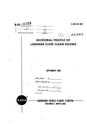
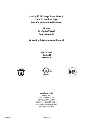
Installing the clean room system6.1Installing the FMS series SuSiThe FMS series SuSi can be installed in the following locations: On a machine Above a table or workstation On the ceiling of a buildingFMS series SuSi installation from above1FMS series SuSi2Profile frame3M6 fillister head screws1. Position the FMS series SuSi (1) flush on the profile frame (2). The internal dimensions of the profile framecan be found in the technical data, see Chapter 3.5, "Internal dimensions of the frame of the laminar flowmodule".2. Screw the FMS series SuSi firmly to the profile frame using M6 fillister head screws (3).3. Check that the FMS series SuSi is firmly positioned.6.0 202029
Installing the clean room systemFMS series SuSi installation from belowNOTICEInstalling the laminar flow module from below allows for a main filter change from below.1Screw2Mounting (not included)3FMS series SuSi4Screw1. Slide the FMS series SuSi (3) through the profile frame from below. The internal dimensions of the profileframe can be found in the technical data, see Chapter 3.5, "Internal dimensions of the frame of the laminarflow module".2. Secure the FMS series SuSi with a mounting (2).306.0 2020
Installing the clean room system3. Screw the FMS series SuSi to the profile frame.4. Check that the profile frame is above the module frame and holds the ceiling bracket on which the ceilingpanels are positioned.Installing a laminar flow module on the ceiling of a building1Ceiling attachments1. Fit the four ceiling mountings on the ceiling of the building.2. Secure the four ceiling attachments to the FMS series SuSi.3. Hook the FMS series SuSi into the ceiling mountings.4. Check that the FMS series SuSi is firmly positioned.6.2Installing the FMS basicWARNING!Risk of injury due to falling main filterThis could result in serious injury or death. Undo the lock plates only when carrying out installation and maintenance. Installation must be carried out by two people.The FMS series basic can be used in the following locations: As a separate filter unit on a machine In combination with a clean room cell6.0 202031
Installing the clean room systemInstallation on a mounting frame1Lock plate2Countersunk screws3FMS series basic4Mounting frame5M6 screws1. Undo the countersunk screws (2) using a hexagonal screwdriver 2.5 or Torx Tx20.2. Remove the lock plate (1).3. Position the FMS series basic (3) flush on the mounting frame (4).4. Screw the FMS series basic to the mounting frame using M6 screws (5).5. Check that the FMS series basic is firmly positioned.326.0 2020
Installing the clean room system6.3Installing the FBS-V series SuSi and EFBS-V series SuSiNOTICENote the weight and mounting points of your laminar flow module, see Chapter 3.3, "Filter sizes".NOTICEHandles may be obtained from Spetec for easier installation.Use suitable lifting equipment for laminar flow modules.Instead of a box made from acrylic glass panes, the FBS-V series SuSi and EFBS-V series SuSi have a cleanroom strip curtain. Consequently, the four mounting points on the FMS series SuSi must be attached to a ceilingmounting.1FMS series SuSi2Profile3Slot nut4Clean room strip curtain5Washer5Cap nut1. Install the FMS series SuSi (1) on the ceiling of the building, see Chapter 6.1, "Installing the FMS series SuSi".2. Attach the clean room strip curtain (2) according to the mark by sliding the holes of the clean room stripcurtain onto the threaded rods.3. Adjust the clean room strip curtain so that its ends seal flush with the device casing.4. Secure the clean room strip curtain using washers (5) and cap nuts (6).6.0 202033
Commissioning7CommissioningDANGER!Danger of death due to residual voltages in capacitors on fan motors.Contact with fan motors could result in death or serious injury. Do not touch metallic parts.Conversion work and maintenance may only be carried out with the clean room system switched off andsecured against reactivation.Commissioning is carried out in stages:1. Setup/installation of the clean room system, see Chapter 6, "Installing the clean room system".2. Connection of the clean room system, see Chapter 7.2, "Connectors".3. Switch-on and setting of the clean room system, see Chapter 8, "Operation".7.1Connecting the cablesNOTICEThere is no fixed sequence for connecting the cables. Nevertheless, Spetec recommends connecting thecontrol cables first and then the cold-device plug for the 230 V power supply.NOTICEThe maximum power consumption of the light output and mains output is 200 W. This value must not beexceeded.Cold-device plugThe cold-device plug (supplied) is used to establish the power supply and inserted into the power socket.Control cablesThe 7-pin control cable (remote) is used to connect multiple modules (master/slave) and to connect the cableremote control. This connection is wired internally only, no signals can be processed.Cold-device socketsAdditional equipment such as lights or signal lamps can be connected to cold-device sockets. A maximum load of200 W must not be exceeded at either connection.346.0 2020
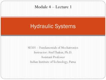
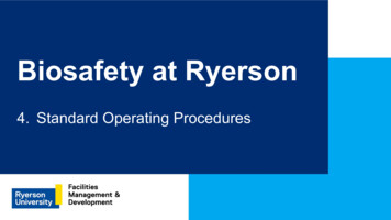
Commissioning7.2ConnectorsSuSi clean room system connectorsFig. 1:Cable connections1Control (7-pin)2Light output3Mains output4Power supply5Device fuse6PLC connection (10-pin)**PLC connection can be optionally installed at the time of purchase. Please observe the supplementaryinstructions.1. If necessary, connect multiple modules using the control (7-pin).2. If necessary, connect a cold-device plug to the light output.3. If necessary, connect a cold-device plug to the mains output.4. Connect the supplied cold-device cable to the power supply.5. Connect the power supply cable to a free socket.The clean room system is ready for operation.6.0 202035
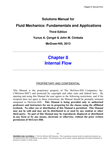
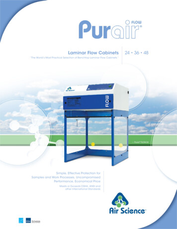
CommissioningBasic clean room system connectorFig. 2:Cable connections7Remote connection8Device fuse9Power supply1. Connect the supplied cold-device cable to the power supply.2. Connect the power supply cable to a free socket.The clean room system is ready for operation.366.0 2020
Operation8OperationDANGER!Danger of death due to electrical voltage to 230 V/50 HzThis could result in death or serious injury. Do not touch live parts. Do not attach earths to mechanical connecting elements.8.1SuSi clean room systemsNOTICEIf call service appears on the display, please contact customer services.DisplayFig. 3:4-row LC
Laminar flow module FMS 37 610 x 610 31 Laminar flow module FMS 56 915 x 610 37 Laminar flow module FMS 75 1220 x 610 52 Laminar flow module FMS 93 1525 x 610 58 Laminar flow module FMS 112 1830 x 610 64 * Special version FMS series basic Designation Filter dimensions in mm Weight in kg Laminar flow module FMS 75 1220 x 610 30 3.3.2 Laminar .