Transcription
2-Hour Fire Endurance Assembly forMPCWT Structural Floor and RoofFraming SystemsEducational OverviewRevised 10/2/2017
SBCA has been the voice of the structural buildingcomponents industry since 1983, providing educationalprograms and technical information, disseminatingindustry news, and facilitating networking opportunitiesfor manufacturers of roof trusses, wall panels and floortrusses. SBCA endeavors to expand componentmanufacturers’ market share and enhance theprofessionalism of the component manufacturingindustry.Copyright 2017 Structural Building Components Association.
Introduction Fire resistance ratings of materials and assemblies are notalways readily available from prescriptive tables and tests. Theoretical methods offer an alternative to full scale fire tests.
Introduction Several historical codes permitfire resistance ratings to bedetermined by analysis: Section 704.1.1 of the 1996BOCA National Building Code Section 703.3 of the 1994Uniform Building Code 701.2.1 of the 1994 StandardBuilding Code
Introduction Current versions of the International Building Code also offerguidance regarding fire-resistance ratings. IBC Section 703.2 IBC Section 703.3 The analysis used in SRR 1509-02 is based on the method listedin IBC Section 703.3, method number 4, Engineering analysis.
Introduction Two items to note: While calculations in accordance with Section 722 (#3) for woodare limited to a maximum of 1 hour (Section 722.6.1.1), thatlimitation does NOT apply to method 4. Prescriptive design in accordance with Section 721 (#2) Table721.1(3), item 28-1.1, includes a ceiling design using I-joists, 3layers of 5/8 Type C gypsum and 7/8 furring channel with a 2hour rating.
Introduction One theoretical method knownas the “Ten Rules of FireEndurance Ratings” waspublished by T.Z. Harmathy inthe May, 1965 edition of FireTechnology. Harmathy’s Rules provided afoundation for extending fireendurance assembly data.These rules are still in use,including extensive use withinthis presentation.
Introduction Fire endurance assembly calculations are also delineated in: Fire Safety Design in Buildings Canadian Wood Council Component Additive Method for Calculating and DemonstratingAssembly Fire Endurance (DCA 4) American Wood Council (AWC) Chapter 7 of BOCA’s Guidelines for Determining Fire ResistanceRatings of Building Elements
Introduction Additionally, the UL Fire Resistance Directory, Design NumberL538 assembly was used in conjunction with the componentadditive method (CAM) principles. The calculations in this presentation are based on CAMprinciples for metal plate connected wood truss construction onbehalf of the Structural Building Components Association.
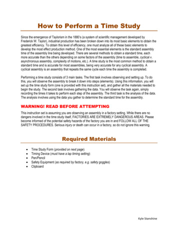
Two Hour Calculated Assembly Fire Rating: 2hours Finish Rating:More than 90minutes
Specifications – (1) Subfloor/Finish Floor Interior plywood or OSB in 4 x 8 sheets 5/8 or greater thickness Manufactured with exteriorglue Have tongue-and-grooveedges along the 8 side
Specifications – (1) Subfloor/Finish Floor Sheets shall be: Installed perpendicular to thetrusses with end joints centeredover the top chord of the truss Placed so the end joints arestaggered Applied in compliance withspecifications andrecommendations provided bythe American PlywoodAssociation.
Specifications – (1) Subfloor/Finish Floor A lightweight concretetopping may be applied overthe plywood or OSB. A topping is not required If applied, this toppingshould be minimum ¾”thick or thicker, following thearchitectural specificationsand topping manufacturer’sguidelines.
Specifications – (2) Structural Members A minimum 12 -deep metalplate connected wood trussspaced at a maximum of 24 o.c. can be used in thisassembly. The truss application shouldfollow the installationrecommendations developedby SBCA.
Specifications – (3) Ceiling Membrane Three layers of Type Cgypsum wallboard are used inthis assembly. Each sheet used is assumedto be a minimum of 4 wide For the most current listing ofacceptable Type C gypsumboard see UL Design NumberL538.
Specifications – (3) Ceiling Membrane The gypsum wallboardattached directly to thetrusses should be orientedperpendicular to the trusses. The gypsum wallboardattached to the furringchannels should be orientedperpendicular to the furringchannels.
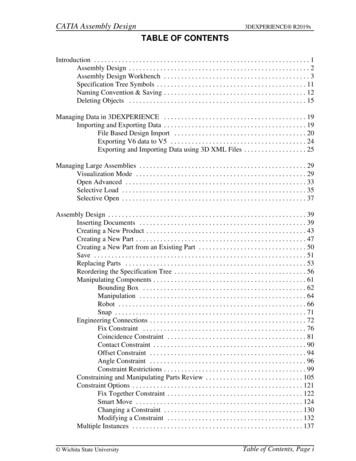
Specifications – (3a) Ceiling Membrane Layer 1 The application of the Type Cgypsum wallboard shallfollow the manufacturer’sinstallation instructions. The wallboard end jointsshould be centered on thebottom chord of the trusses,and should be staggered.Ceiling Membrane Layer 1Material5/8 Type C gypsum wallboardAttached toBottom chord of trussFastener type1-1/4 Type S bugle-head screwSpacing alongedges/in field6:12Minimum enddistance3/8 Minimum edgedistance1-½
Specifications – (3b) Furring Channel Resilient or inverted hat-typefurring channels are placedover the first layer of gypsum The channels are made of 25gauge galvanized steel, andinstalled perpendicular to thestructural members. Channel spacing: max 24 o.c. Attached to each truss(through the gypsum) with one1-7/8 Type S screw.
Specifications – (3c) Ceiling Membrane Layer 2 This middle layer of 5/8 Type C gypsum wallboard isattached to the furring orresilient channels. The end joints of eachgypsum wallboard sheet shallbe centered on the resilientor furring channel.Ceiling Membrane Layer 2Material5/8 Type C gypsumwallboardAttached toFurring/resilient channelFastener type1-1/4 Type S bugle-headscrewSpacing6 maximumMinimum end distance5/8 Minimum edge distance1-½
Specifications – (3d) Ceiling Membrane Layer 3Ceiling Membrane Layer 2 The end and edge joints of the finish layerof gypsum should be staggered aminimum of 24 from the joints in layer 2.The end joints of the face layer must becentered on the furring channels. If this is not the case, end joints shall beattached to Wallboard Layer 2 with 11/2 Type G screws spaced 6 o.c. withan end and edge distance of 1-1/2 .All screws shall be set so that they areflush with the face of the wallboard anddo not damage the core of the wallboard.Material5/8 Type C gypsumwallboardAttached toFurring/resilient channelthrough Layer 2Fastener type1-5/8 or 1-7/8 Type Sbugle-head screwSpacing6 maximumMinimum end distance5/8 Minimum edge distance1-½
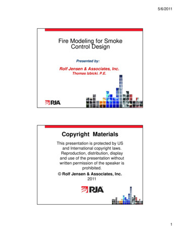
Specifications – (4) Fasteners Type S bugle head screwsthat are self-drilling and selftapping shall be used. Where needed, Type Gwallboard screws can also beused. Screws shall meet ASTMC1002 or ASTM C954standards.Type GType S
Specifications – Finishing Systems The face layer joints shall becovered with tape and coatedwith joint compound. Screws shall also be coveredwith joint compound.
Analysis – Membrane Protection The critical feature of a fire endurance assembly, particularly ahorizontal assembly, is the performance of the gypsummembrane. For an assembly to obtain a given fire endurance resistanceperformance, the membrane must stay intact for the full durationof fire resistance performance before falling off.
Analysis – Membrane Protection Harmathy states: “The thermal fire enduranceof a construction consistingof a number of parallellayers is greater than thesum of the thermal fireendurance characteristics ofthe individual layers whenexposed separately to thefire.”
Analysis – Membrane Protection For example, a single layer of1/ gypsum wallboard yields2a membrane rating of 15minutes. If two such layers are used,the rating is 40 minutes,instead of the expected 30.Wallboard Membrane Description3/ Douglas fir plywood phenolic8bonded1/ Douglas fir plywood phenolic2bonded5/ Douglas fir plywood phenolic8bonded3/ gypsum wallboard81/ gypsum wallboard21/ Type X gypsum wallboard25/ gypsum wallboard85/ Type X gypsum wallboard8Double 3/8 gypsum wallboard1/ and 3/ gypsum wallboard281Double /2 gypsum wallboardTime (minutes)510151015252040253540
Analysis – Membrane Protection Another rule states that the fireendurance of a constructiondoes not decrease with theaddition of additional layers. By adding layers of material,both the resistance to heatflow and heat capacity of theconstruction increase. This reduces the rate oftemperature rise in the plenum,and therefore, at theunexposed surface.
Analysis – Membrane Protection However, the added layer: Must have similar thermalexpansion and transmissionproperties to the adjacent layer Must be made of a thermallyresistant materialIn other words, adding a layer ofsteel to the unexposed surfacewould not enhance the fireperformance of the assembly,whereas adding a plaster layerwould.
Analysis – Membrane Protection The table at right shows aprotective membrane of 120minutes using the CAM. Direct addition of membranetimes is conservative, based onthe rules and the 1/2 gypsumwallboard example given. Type C gypsum is specifiedand is conservative, since ithas much better fire enduranceperformance than Type X.Wallboard Membrane Description Time (minutes)5/ Type X gypsum wallboard4085/ Type X gypsum wallboard4085/ Type X gypsum wallboard408Total120
Analysis – Performance Enhancements Harmathy states that the fireendurance of constructionswith continuous air gaps orcavities is greater than the fireendurance of equivalentconstructions without air gapsor cavities. This occurs because theinsertion of voids providesadditional resistance to heatflow, similar to a storm window
Analysis – Performance Enhancements Inserting resilient channelsbetween Wallboard Layer 1 ofthe assembly and the twolayers below it serves severalfunctions. First, it creates a continuousair space that enhances thefire performance of themembrane system and createsdead air space that isinsulating.
Analysis – Performance Enhancements Second, attaching the resilientchannel over the first layer ofgypsum provides additionalsupport for, and thereforeenhances the stability of, thefirst layer of gypsum wallboard. This will aid in keeping thislayer of gypsum in place,resulting in better assemblyfire performance.
Analysis – Performance Enhancements Finally, there will be twoconnection points of the first layerinto the truss system. The first will be attaching thegypsum layer to the truss. The second will be attaching theresilient channel through the firstgypsum layer into the truss.This will enhance the stability ofthe membrane attachment,keeping layer 1 on longer, andimproving the overall fireperformance of the assembly
Analysis – Performance Enhancements An analysis for the National FireProtection Research Foundation(NFPRF), National EngineeredLightweight Construction FireResearch Project (Design FC-240and Design FC-235) indicated anadditional 6 minutes ofperformance due to the addition ofresilient channels.For the assembly described above,the following calculation couldthen be made:Description3 layers of 5/8 Type X gypsumwallboardResilient channels spaced to amaximum of 16 o.c.TotalTime (minutes)1206126
Analysis Note that the multiple layer effect has not yet been taken intoaccount. This membrane could be calculated as at least a 136 minuteassembly by adding the 10 minute performance increase, usingthe 2 layers of 1/2 gypsum example shown earlier.Description3 layers of 5/8 Type X gypsum wallboardResilient channels spaced to a maximum of 16 o.c.Credit for Multiple Layers of GypsumTotalTime (minutes)120610136
Analysis – Engineering Evaluation To evaluate the reliability and reasonability of this assembly, ASTM E119 testingcan be reviewed.There are three examples of assemblies that utilize 2 layers of 5/8 Type Cgypsum wallboard: UL L505 – 75 minutes L511 – 71 minutes L538 – 90 minutesIn these assemblies, the resilient channel was spaced 24 o.c., and the wallboardwas attached with 8d nails spaced 7 o.c.These tests illustrate the endurance performance of the wallboard, and providethe time it took for this membrane and connection system to provide thermalprotection of the assembly to 250 F plus ambient on average, or 325 F, plusambient at a single point.
Analysis Two metal plate connected truss tests indicate single gypsum layer finish ratingwith trusses spaced at 24" o.c. Factory Mutual FC-235 shows 5/8" USG Type C board – 24 minutes PFS 88-03 shows 5/8" USG Type C board – 23 minutesPerforming a combined finish rating analysis yields:DescriptionSingle layer of 5/8" Type C wallboard attached to TrussesResilient channels5Single layer of /8" Type C wallboard attached to resilient channelsSingle layer of 5/8" Type X or Type CFinish rating range of performanceTime (minutes)71-7523-2494-99
Analysis This range is conservative given the additive rule. This analysis shows the time it takes the back side of thewallboard to reach an average of 250 F above the ambienttemperature (approximately 250 70 320 ), which is wellbelow the temperature that wood begins to char (482 F).
Analysis The performance of the trusses in the fire test assemblies FC235 and PFS 88-03 after the finish rating was reached was 26and 29 minutes, respectively. By adding these values to the finish rating range of performanceabove, we have:DescriptionFinish Rating Range of PerformanceTruss Performance after Finish rating is achievedAssembly Performance RangeTime (minutes)94-9926-29120 – 128
Analysis The ASTM E119 testing justifies the fire endurance performanceshown previously. Including the beneficial effect of multiple gypsum layers will add aminimum of 10 minutes to the performance, for a final range of 130 138 minutes, which is in excess of the 2-hour rating desired.DescriptionFinish Rating Range of PerformanceTruss Performance after Finish rating is achievedBeneficial Effect of Adding Gypsum Layers TogetherAssembly Performance RangeTime (minutes)94-9926-2910130 – 138
Analysis – Connection System In order for the membranesystem to protect the trussesfrom the impact of fire, theconnection detailing becomesextremely important. The connections must hold thegypsum membrane in placeduring the exposure time andhave enough withdrawalresistance to hold the deadload of the gypsum wallboard.
Analysis – Connection System To determine whether thefastening of the assembly isadequate, we need todetermine for each fastener inthe system: The weight of gypsum thatmust be held by the fastener(dead load) The withdrawal resistance ofthe fastener from thesubstrate it penetratesLoading (Layer 1)Spacing of trusses24 o.c.Spacing of screws6 o.c.Area of gypsum eachscrew must hold1 ft2Number of layers1Weight of Type C gypsumper layer2.5 psfWeight of gypsum heldby each screw2.5 lb
Analysis – Connection SystemWithdrawal Resistance (Layer 1) Withdrawal calculations arebased on the 2015 NationalDesign Specification forWood Construction. With a withdrawal resistanceper screw of 43.125 lb, theFastener 1 connection is farstronger than the 2.5 lbrequired.Type of fastener1-1/4 Type S, 6gaugeWood specific gravity (SPFor better)0.42Withdrawal value of screwfrom wood69 lb/in.Thickness of gypsum5/8 Penetration into wood5/8 Withdrawal resistance perscrew43.125 lb
Analysis – Connection SystemLoading (Channel) For the channel attachmentwe can perform a similarcalculation. For this connection, thefastener is attached throughthe resilient channel andgypsum to the truss.Spacing of resilientchannel24 o.c.Spacing of joists24 o.c.Area of gypsum eachscrew must hold4 ft2Number of layers2Weight of Type C gypsumper layer2.5 psfWeight of gypsum heldby each screw20 lb
Analysis – Connection System1-7/8 Using aType S screwthat penetrates a 5/8 thicklayer of gypsum and theresilient furring channel leavesapproximately 1-1/4 ofpenetration. Each screw holding theresilient channel to the joistcan handle 86.25 lb, which isfar greater than the 20 lbrequired.Withdrawal Resistance (Channel)Type of fastener1-7/8 Type SWood specific gravity (SPFor better)0.42Withdrawal value ofscrew from wood69 lb/in.Thickness of gypsum5/8 Penetration into wood1-1/4 Withdrawal resistanceper screw86.25 lb
Analysis – Connection SystemLoading (Layer 2) Next, the middle layer of thewallboard should be attachedto each furring or resilientchannel.Spacing of resilientchannel24 o.c.Spacing of screws6 o.c.Area of gypsum eachscrew must hold1 ft2Number of layers1Weight of Type C gypsumper layer2.5 psfWeight of gypsum heldby each screw2.5 lb
Analysis – Connection SystemWithdrawal Resistance (Layer 2) The calculated withdrawalresistance of the specifiedscrew penetrating theresilient channel is 60 lb,which far exceeds the 2.5 lbrequired.Type of fastener1 or 1-1/4 Type SResilient Channel25 gauge, 33 ksiWithdrawal value ofscrew from channel60 lb
Analysis – Connection SystemLoading (Layer 3) Finally, the face layer of thewallboard is attached to eachfurring or resilient channelthrough the middle layerwallboard.Spacing of resilientchannel24 o.c.Spacing of screws6 o.c.Area of gypsum eachscrew must hold1 ft2Number of layers1Weight of Type C gypsumper layer2.5 psfWeight of gypsum heldby each screw2.5 lb
Analysis – Connection System The withdrawal resistance of60 lb per screw in resilientchannels is more thansufficient to carry the load. Each fastener in theassembly is more thanadequate to support the deadloads it must carry.Withdrawal Resistance (Layer 3)Type of fastener1-5/8 or 1-7/8 Type SResilient Channel25 gauge, 33 ksiWithdrawal value ofscrew from channel60 lb
Analysis – Assembly Modifications(Depth/Spacing) The trusses in this designhave a minimum depth of 12 . Trusses with depths greaterthan 12 may be used. Per GA-600, dimensionsincluded for depth ofassemblies are minimums,spacings are maximums.
Analysis – Assembly Modifications(Insulation) Both UL and GA include specific guidanceregarding the use of insulation inassemblies. Many designs listed by UL BXUV allowaddition of any depth of insulation at anylocation in an assembly that does notinclude insulation, but only as long as anadditional layer of identical gypsum isinstalled at the ceiling. Any other method of adding insulation isprohibited in assemblies tested withoutinsulation.GA-600 includes a similar provision.
Analysis – Assembly Modifications(Insulation) However, IBC 703.3 methods #4 or#5 do allow modifications toassemblies, which would includeinclusion or placement of insulation,based on rational design provided tothe building official.In deeper trusses, the space abovethe 12 plenum depth may containinsulation, provided the insulation issupported adequately so that theplenum depth is maintained at 12 from the backside of the gypsum dueto the conservative designmethodology.
Conclusion This assembly has been analyzed and shown to achieve a 2-hour fire enduranceperformance rating, based both on the component additive method (CAM) andverified by comparison to existing ASTM E119 tested assemblies.We have deliberately been conservative in the development of this assembly toensure 2-hour performance in the following ways: Type C gypsum wallboard is specified instead of Type X.― This wallboard has proven to be a more stable wallboard, and we feel it will moreadequately protect the truss assembly. By placing the resilient channels over the top of wallboard layer 1, the channels willhold the wallboard in place and enhance the performance of the fire enduranceassembly.― This is due to the increased likelihood the wallboard will not fall away from thetrusses prematurely.
Conclusion Additionally: The Type S gypsum wallboard screws are spaced at 6 o.c. to providegood connection support of the wallboard membrane.―We have also checked the loads carried by each fastener to ensurethat there is a large margin of reserve capacity for each screw.―The key to an assembly's performance is an intact membrane.―This fastener schedule seeks to ensure the membrane will stayintact and perform as expected. Given the above, we are confident that the described assembly willafford a 2-hour fire endurance performance as required by thebuilding code.
References SBCA Research Report 1509-01National Design Specification for Wood Construction (NDS ) 2012 or 2015,American Wood Council (AWC), Section 16, Fire Design of Wood Members.Analytical methods for determining fire resistance of timber members, RobertWhite, 2008, included in the SFPE handbook of fire protection engineering.Quincy, Mass.; National Fire Protection Association; Bethesda, Md.: Societyof Fire Protection Engineers, c2008: pages 4.346-4.366.Guidelines on Fire Ratings of Archaic Materials and Assemblies.International Code Council (ICC).National Building Code of Canada, 2010.
References International Building Code (IBC), 2012 and 2015, International Code Council(ICC).BXUV.GuideInfo, Underwriters Laboratory.Gypsum Association Handbook, GA-600, 2012Fire Resistance Provided by Gypsum Board Membrane Protection, GA-610,2013ESR-1338, Gypsum Wall and Ceiling Assemblies and Gypsum Board Interiorand Exterior ApplicationsIntertek Directory of Certified ProductsPFS CorporationFactory Mutual
principles for metal plate connected wood truss construction on . bottom chord of the trusses, and should be staggered. Ceiling Membrane Layer 1 . gauge galvanized steel, and installed perpendicular to the structural members. Channel spacing: max 24 o.c.