Transcription
5/6/2011Fire Modeling for SmokeControl DesignPresented by:Rolf Jensen & Associates, Inc.Thomas Izbicki. P.E.Copyright MaterialsThis presentation is protected by USand International copyright laws.Reproduction, distribution, displayand use of the presentation withoutwritten permission of the speaker isprohibited. Rolf Jensen & Associates, Inc.201121
5/6/2011Overview Smoke Control RequirementsSmoke Control Design ConsiderationsFire Model TypesCase StudyQuestions3Smoke Control Requirements Early Prescriptive Requirements (up toearly 1990’s)– AirAi ChChanges– Operable Windows Current Prescriptive Requirements– Passive or active smoke control– Based on design fire and specificguidelines for feature being protected Performance Requirements– Establish Performance Goals– Outline Design Method Acceptance Testing Requirements42
5/6/2011IBC Smoke Control Prescriptive requirements based onspecific objectives Design Guidelines - Section 909 Specific requirements based onbuildingbud g featureea u e bebeinggpprotectedo ec ed5Building Features with SmokeControl Provisions: Co e ed MallCovereda Buildingsu d gs (Sect(Sectiono 402)0 )Atriums (Section 404)Underground Buildings (Section 405)Stages (Section 410.3.7)Stair Protection (Section 1005.3.2.5)Smoke Protected Assembly Seating(S ti 1008.5.2)(Section1008 5 2) Pedestrian Bridges/Tunnels (Section3104)63
5/6/2011Atria/Covered Malls Atrium is typical feature for smokecontrol considerations Refers to IBC Section 909, SmokeControl Systems– Pressurization Method– Airflow Method– ExhaustE ha st Method Exhaust Method considered mostapplicable to atria/covered malls7IBC Smoke ControlMethodologies Pressurization Method (“zoned approach”)– Need a barrier for pressure differential such assmoke barrier Airflow Method– Most often used in combination with anothermethod Exhaust Method– Most common Analysis- Stack Effect- Temperature Effect- Wind Effect- HVAC Systems- Climate- Duration of Operation84
5/6/2011Pressurization Method Maintain pressure difference across smokebarriers– Minimum 0.05 inch water gage– Maximum based on door opening/closing forces Problems– Building may be tighter or looser than calculated– Oversizing fans means door opening problems– Balancing with stairs9Airflow Method Can be used for unprotected verticalopenings between zonesqthroughg openingpg ((fpm):p ) Velocityy requiredv 217.2 [h (Tf - To) Tf 460) ] 1/2Where:h height of opening - ft.Tf Temperature of smoke - FTo Ambient temperature - F Airflow cannot exceed 200 fpm.105
5/6/2011Exhaust Method Used for large enclosed volumes Maintain smoke 10 ft. or 6 ft. above highestwalking surface used for egress Make up air by natural or mechanical meansis required Maximum make up air velocity -- 200 fpm Exhaust high and supply low Plugholing Analyze balcony conditions11Exhaust Method Based on plume type– Axisymmetric– Balcony spill– Window126
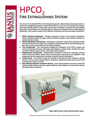
5/6/2011Axisymmetric Plume Prototypical plume Cone with tip atbottom Air entrained on allsides13Axisymmetric Plume Used when no obstructions to theplume Determine Flame Heightz l 0.533 Qc 2/5where z l flame heightQc convective heat release - usually 70%of fire size147
5/6/2011Axisymmetric Plume Determine Formula to Use– Smoke layer must be at least 6 feet abovehighest walking surface (z)– 3 formulas depending on flame heightvs required smoke layer heightIf z z 1 mp 0.0208 Qc 3/5 zIf z z 1 mp 0.0011 QcIf z z 1 mp 0.022 Qc 1/3 z 5/3 0.0042 Qc- Note impact of z where clear height isgreater than flame height15Axisymmetric Plume Convert mp (mass flow rate) to V(volumetric flow rate)v 60 mp / wherev volume in cfmmp mass in lbs/sec density at smoke temp. in3lbs/ft.168
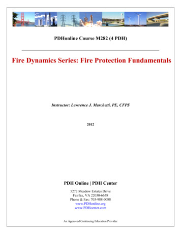
5/6/2011Axisymmetric Plume Result shows exhaust rate (fan size) Problems:P bl must know fire size very dependent on height does not address large areaspaces does not address dilution Conservative for tall, small spaces17Balcony Spill Plume189
5/6/2011Balcony Spill Plume Used where smoke may spread acrossceiling before reaching open area Determine fire size and dimensions ofspace– H height from fire to underside ofbalcony– W width of spill between architecturalprojections– zb height from balcony to bottom of clearlayer19Balcony Spill Plume– Results in very high numbers– What is a realistic plume width?– Controversy about whether resultsare realistic for sprinkler protectedspaces– Much discussion regarding balconyspill plume correlations2010
5/6/2011Window Plume21Window Plume Least used plume correlation Application is limited– Fire confined to room– Effect of sprinklers in room– Mayy be used if separationpis gglass orunrated construction2211
5/6/2011Other Considerations PlumePlContactC t t withith WWallll– Plume contact affects entrainment– Formula provided to estimate plume width– Plume flow rate can be consideredconstant once it hits the wall23Exhaust Method Plugholing2412
5/6/2011An Example Atrium Axisymmetric vs. Balcony Spill Plume– 50-foot tall atrium Axisymmetric Plume– 5,000 Btu/s design fire– 148,000 cfm Balcony Spill Plume 1– 5,000 Btu/s fire– 12-foot spill width– 372,000 cfm Balcony Spill Plume 2– 2,000 Btu/s fire (sprinkler control)– 12-foot spill width– 274,000 cfm25Design Fire Code guidance– 2003 IBC 5,000 Btu/sec (5,275 kW) minimum May be modified with rational analysis System duration:– 20 minute minimum– 2006 IBC Based on a rational analysis System duration (the least):– 20 minutes, or– 1.5 times the calculated egress time– NFPA 92B Performance based design2613
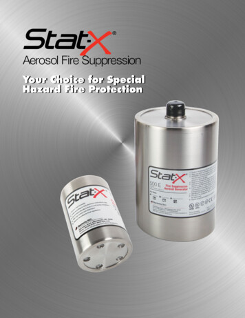
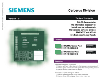
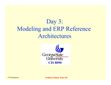
5/6/2011Design Fire Fire Test Results272 Panel Workstation Fire0min, 10kW1min, 10kW2min, 70kW4min, 680kW5min, 1.7MW8min, 1.3MW12min, 960kW14min, 880kW3min, 215kW10min, 1.1 MW20min, 750kW28min, 480kW2814
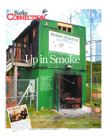
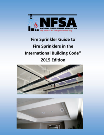
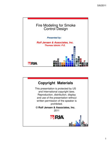
5/6/2011NIST Design Fire DataNIST Design Fire DataSofaTwo panel work stationThree panel work stationFast FireLoveseat7000Heat Release Rate Time (s)29Typical Design Fire CurveScenario 2 : Second floor beneath 3rd floor balcony.Sofa with sprinkler activation at 371secondst2 fire with 150 second characteristic growth timeLove Seatgrowth time 150 secondsSprinkler controlled fire70006000Heat Release Rate (kW)500040003000200010000020040060080010001200Time (s)3015
5/6/2011Typical Design Fire CurveFire Scenario 1 Heat Release RateLoveseat 1TableLoveseat 2TOTAL ENERGYFast t-squared fire45004000350030002500HRR (kW)2000150010005000020040060080010001200Time (seconds)31Fire Model Types Algebraic Equations Zone models– One zone– Two zones Field models– Computational fluid dynamics (CFD)3216
5/6/2011Algebraic Equations Equations– Specific phenomenon– Finite applicability– Simple algebra Identify variables Solve equation– Calculator or spreadsheet33Algebraic Equations AlpertAlpert’ss ceiling jet correlations– Temperature– Velocity– Variables Ceiling height (H) Radial distance from fire to point of interest (r) Fire size (Q)3417
5/6/2011Algebraic Equations Alpert’sAlpert s equations for ceiling jettemperature and velocity35Algebraic Equations Alpert’sAlpert s equations for ceiling jettemperature and velocity5.38 Q / r 3 H12T Tambr/H 0.18U 10.195Q 3 H 25r6r/H 0.153618
5/6/2011Algebraic Equations AlpertAlpert’ss ceiling jet correlations– Limits of applicability Geometry– Unconfined smooth ceiling– Ratio of r/H Fire size– 668 kW Q 98 MW37Zone Models3819
5/6/2011Zone Models39Zone Models Conservation of massConservation of energyIdeal gas lawSolution– Ordinary differential equations– Algebraic equations– 2 dimensions4020
5/6/2011Zone Models Dedicated computer program Spreadsheet approximations NIST CFAST– Technical Reference Validation Sensitivity Robustness41Field Models4221
5/6/2011Field Models Conservation of massConservation of energyConservation of momentumIdeal gas lawSolution– Partial differential equations– 3 dimensions43Field Models Dedicated computer program Spreadsheets not possible NIST Fire Dynamics Simulator (FDS)– Technical Reference (3 volumes) Mathematical model & numerical method Validation Verification4422
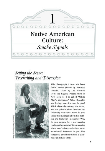
5/6/2011Case Study Two (7)-story( )yuniversitybuildings Five-story atriumconnecting thenorthth andd souththtowers454623
5/6/201147Design Parameters Axisymmetric Plume Scenario– Furniture Group– 177 second characteristic growth time– Peaks at 350 seconds– 4,115 kW fire4824
5/6/2011Design Parameters Balcony Spill Plume Scenario– Single piece of upholstered furniture– 150 second characteristic growth time– Automatic sprinkler activation at 130seconds– 799 kW fire49Design Parameters Failure Criteria– Visibility Greater than 33 feet (10 meters)– Upper Layer Temperature Less than 120 ºF (49ºC) (single point)– Carbon Monoxide Less than 3,000 ppm (single point)5025
5/6/2011FDS Model Elevations51Axisymmetric Plume Analysis– IBC 909 calculations 5 stories open– 5,275 kW (5,000 Btu/sec) fire– 230,000 cfm at the top of the atrium 3 stories open– 5,275 kW (5,000 Btu/sec) fire– 130,000 cfm at the top of the atrium– CFAST Simulation 3 stories open– 4,115 kW fire– 200,000 cfm at the top of the atrium5226
5/6/2011Axisymmetric Plume Analysis– FDS Simulation 3 stories open– 4,115 kW fire– 70,000 cfm at the top of the atrium53Axisymmetric Plume5427
5/6/2011Balcony Spill Plume Analysis– IBC 909 calculations 5 stories open– 768 kW (728 Btu/sec) fire– 216,000 cfm at the top of the atrium 3 stories open– 768 kW (728 Btu/sec) fire– 130,000 cfm at the top of the atrium– FDS Simulation 3 stories open– 799 kW (757 Btu/sec) fire– 140,000 total exhaust» 100,000 cfm at the top of the atrium» 20,000 cfm above the 2nd and 3rd floor balconies55Balcony Spill Plume5628
5/6/2011Summary Unexpected phenomena due togeometry IBC/NFPA 92B equations don’t addressinlet locations Engineeredg ee ed aanalysisa ys s doesdoesn’t alwaysa aysreduce the exhaust quantity57Thank You For Your Time!Questions?This concludes theContinuing Education Programrjainc.com1-888-831-4RJA29
Roles of AEC Team Members in SmokeControl System DesignProtection Development, IncorporatedPresented by: Gilead R. Ziemba, P.E., M.Sc.2014 Protection Development, Incorporated
Objectives Understand each team members role in thesuccessful implementation of a smoke controlsystem Identify ways each member can improve theprocess2014 Protection Development, Incorporated
Overview Introduce the usual suspectsIdentify broad responsibilitiesWalk through a timeline of the processHighlight key aspects of the process withemphasis on roles and responsibilities2014 Protection Development, Incorporated
Team Org ChartAHJOwner/DeveloperArchitectGeneral ContractorA/E Team MembersSub-ContractorsCxA / 3rd Party /Special Inspector2014 Protection Development, Incorporated
Team Org ChartAHJCxA / 3rd Party / Special InspectorOwner/DeveloperGeneral ContractorArchitectSub-ContractorsA/E Team Members2014 Protection Development, Incorporated
Who are the Players? Owner/DeveloperArchitectGeneral ContractorFire Protection EngineerAHJ– Building/Fire Official– Insurance Carrier2014 Protection Development, Incorporated
Who else is involved? MEP Engineer – Works in conjunction with theArchitect and FPE to select, or assist inselection of products and design of thesystem.2014 Protection Development, Incorporated
Who else is involved? Testing and Balancing Contractor – Works inconjunction with Special Inspector tocommission the system. Fire Alarm Contractor – Primary systemcontrols. Sprinkler Contractor – Interface with systemcontrols.2014 Protection Development, Incorporated
Who else is involved? HVAC Contractor – Major system components. Interior Designer – Furniture selection. Specialties Contractor – Special systemcomponents.2014 Protection Development, Incorporated
Who else is involved? That’s at least 14 different entities!!!2014 Protection Development, Incorporated
What does the Code say? The Building Official (AHJ) shall:– Receive, review, and issue permits forconstruction (IBC 104.2)– Render interpretations of the Code (IBC 104.1)– Make all required inspections or accept reports ofinspection (IBC 104.4)2014 Protection Development, Incorporated
What does the Code say? The Owner (or authorized agent) shall:– Apply for and obtain all required permits (IBC105.1)– Engage and designate a Registered DesignProfessional in Responsible Charge (RDPiRC) (IBC107.3.4)– Engage the Special Inspector (IBC 1703.1.1)2014 Protection Development, Incorporated
What does the Code say? The Architect (RDPiRC) shall:– Review and coordinate submittal documentsprepared by others for compatibility with thedesign of the building (IBC 107.3.4)– Prepare a statement of special inspections (IBC1704.3)2014 Protection Development, Incorporated
What does the Code say? The FPE / ME(Registered Design Professional)shall:– Prepare Construction Documents. (IBC 107.1)– Prepare a rational analysis supporting the types ofsmoke control systems to be employed and theirmethods of operation. (IBC 909.4)– Sign, seal, and date the final complete report oftesting by the Special Inspector. (IBC 909.18.8.3)2014 Protection Development, Incorporated
What does the Code say? The Special Inspector shall:– Be objective, competent and independent from thecontractor responsible for the work being inspected.(IBC 1703.1.1)– Keep records of special inspections and furnishreports to the Building Official and RDPiRC. (1704.2.4)– Have expertise in fire protection engineering,mechanical engineering, and certification as airbalancers. (IBC 909.18.8.2)– /upload/IB132SpecialInspections.pdf.pdf2014 Protection Development, Incorporated
What does the Code say? The Contractor shall:– IBC has no defined role for the Con
– NFPA 92B Performance based design 26. 5/6/2011 14 Design Fire Fire Test ResultsFire Test Results 27 2 Panel Workstation Fire 0min, 10kW 1min, 10kW 2min, 70kW 3min, 215kW 4min, 680kW 5min, 1.7MW 8min, 1.3MW 10min, 1.1 MW 12min, 960kW 14min, 880kW 20min, 750kW 28min, 480kW 28. 5/6/2011 15 NIST Design Fire Data NIST Design Fire Data Sofa Two panelworkstation Three