Transcription
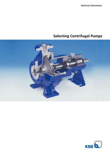
FUNDAMENTAL PRINCIPLES OF PRESSURE REGULATORSPresented by Kevin ShawActaris Metering Systems970 Hwy. 127 North, Owenton, KentuckyINTRODUCTIONThe following paper will concentrate on the fundamentalsand principles of natural gas pressure regulators. In thegas regulator’s conception it was mainly a device usedto reduce high pressure to a more usable lower pressure.Today, more is expected from the performance of thepressure regulator. Pressure reduction is no longer theonly function needed. The regulator is considered anintegral measurement instrument that must adhere tothe stringent codes put forth by the U.S. FederalDepartment of Transportation and many state PublicUtility Commissions.LoadingElementSensingElementIn order to understand the principles of pressureregulation this paper will focus on:I. OPERTIONII. DROOP VS. BOOSTIII. CHANGING IN INLET PRESSURE VS.MECHANICAL ADVANTAGEIV. SAFETY MECHANISMSV. KEYS TO SELECTIONVI. CONCLUSIONSREGULATOR CLASSIFICATIONSWith few exceptions, gas pressure regulators can beclassified into either of the following two categories:1. Self-Operated Regulators (also known as SpringLoaded)2. Pilot Regulators Constant-Loaded (a.k.a. Pilot-Loaded) Pilot Operated (a.k.a. Two-Path Regulation) Pilot Unloading (a.k.a. Pressure Unloading)The Pilot Regulator category can further be classified intothe three sub-categories of Constant-Loaded, PilotOperated, and Pilot Unloaded. Make no mistake; thesethree design are vastly different and, thus, will exhibitsignificantly different performance characteristics. Eachof these designs is covered in more detail later in the paper.REGULATOR DEFINITIONA pressure regulator is a feedback control mechanismdesigned to maintain a constant downstream pressurethrough the manipulation of gas flow. By definition, aregulator is composed of three essential components(see Figure 1 illustration):PAGE 262003 PROCEEDINGSAMERICAN SCHOOL OF GAS MEASUREMENT TECHNOLOGYRestricting ElementFIGURE 1.1. Restricting Element — A restriction which allowsgas to flow through the regulator at a reducedpressure to meet downstream demand. In mostcases this consists of a resilient valve seat (plug)and a sharp edged orifice.2. Measuring Element — A device that continuouslysenses changes in downstream pressure caused bychanges in downstream demand and transmits asignal to open or close the restricting elementaccordingly. This is typically an elastomericdiaphragm.3. Loading Element — Adjustable force which iscontinuously compared to the downstream pressureby the measuring element to determine what signal(open/close) to transmit to the restricting element.In pilot regulators the loading element is gaspressure.SPRING-LOADED REGULATOR OPERATIONThe main function of any regulator is to provide a flow ofgas through the regulator to match the downstreamdemand while holding pressure constant. In a springloaded regulator three devices are employed to achievethis — a restricting device (usually an orifice); a sensingdevice (diaphragm); and a loading device (spring orpressure). Tying these three things together is a
mechanical linkage (usually called the valve stem and/or lever) that acts like a “see-saw.” The linkage works tobalance the forces associated with the three abovedevices.A pseudo free-body diagram gives a representation ofthis balancing act is shown in Figure 2.[ ][ ]Fi P1 AoWhere: P1 Inlet PressureAo Orifice AreaThe downstream pressure under the diaphragm createsa closing force (Fo) pushing against the diaphragm tryingto close off the flow of gas. This force is calculated as: Effective outlet Fo X diaphragm pressure area FIGURE 2. Regulator Force BalanceIn all regulators two types of forces exist: 1) openingand 2) closing forces. These two forces act on themechanical linkage with one trying to close the valve(shutting off gas flow) while the other works to open thevalve (increasing gas flow). Under steady operation thesums of the opening and closing forces are always equalbut opposite in direction giving a static equilibriumcondition. As in any static equilibrium condition, the valvewill remain in a fixed position until one of the forceschange, upsetting the equilibrium. The valve will thenreposition again until the forces are again in equilibrium.In a spring-loaded regulator, the sum of forces on themechanical linkage can be expressed as follows:Opening Forces Closing ForcesorFi Fs FoIn normal operation, the diaphragm will sense the outletpressure force change and provide a force to the linkage.The linkage moves to control the flow through the valveto maintain the set outlet pressure. For instance, if theoutlet pressure drops from the set pressure, the forceunder the diaphragm Fo decreases allowing the springforce Fs to reposition the diaphragm. This downwardtravel acts to move the valve seat away from the orifice,bringing the outlet back to approximately the desiredset pressure. If the outlet pressure increases, the reversehappens. The linkage responds to the increased outletpressure force and tends to restrict the orifice. The flowis reduced and the outlet pressure once again returnsapproximately to the set pressure.In a perfect world our loading element (the spring) wouldsupply a constant force, there would be no friction withinthe regulator or material hysteresis. If this were the casethe regulator would supply a constant outlet pressureover an infinite range of gas flows. However, thisperformance is unattainable. Hindrances like 1) springforce linearity (Hooke’s Law) and 2) the change in effectivediaphragm area as the valve travels, effect theperformance of the regulator. In Figure 3 typical springloaded regulator performance is shown.Where:Fi Inlet Pressure ForceFs Spring ForceFo Outlet Pressure ForceThis equation assumes there are no frictional effectsinside the regulator.The opening forces consist of one mechanical and onepneumatic load. The high-pressure inlet gas creates apneumatic force (Fi) pushing on the face of the valveseat forcing open the valve. An adjustable spring force(Fs) assists the high inlet pressure by pushing on thesensing device (diaphragm), opening the valve tomaintain the set pressure. These forces can be calculatedas follows:[ ][ ]Fs K x (Hooke’s Law)Where:K Spring Constant (lb./in.)x Spring Compression (in.)FIGURE 3. Typical Spring-Loaded Regulator PerformanceThe performance loss due to these effects is calledpressure droop. Droop, and outlet pressure loss belowset with increasing flow, is an ever-present problem in2003 PROCEEDINGSPAGE 27AMERICAN SCHOOL OF GAS MEASUREMENT TECHNOLOGY
the performance of the regulator. To combat the effectsof droop, a method called “boost” is employed. A betterunderstanding of these principles will follow in the nextsection.Mechanical advantage can answer this dilemma. Thisadvantage, know as power ratio, directly relates to thediaphragm size and linkage ratio or the amount of travelof the diaphragm with respect to the valve seat. The largerdiaphragm gives more force at a given pressure andcombined with the lever ratio will equalize the outletpressure over a range of changing inlet pressures.Figure 4 shows a typical example of the effects ofchanging inlet pressure. Raising the inlet pressure fromset pressure (curve “set”) tends to increase the outletpressure (curve “ ”). A reduction in inlet is observed inthe bottom curve (“ ”).SAFETY MECHANISMSFIGURE 4. Inlet Pressure Effect on PerformanceDROOP VS. BOOSTOne contributor to droop is spring effect. Spring effectis a result of the reduction in spring force when thediaphragm and valve are in the wide-open position (fullydown). The reduction in the spring force requires a loweroutlet pressure to balance it. The second contributor todroop is diaphragm effect. As with spring effect, the wideopen valve position (fully down) is again the problematicdiaphragm position. The effective diaphragm areaincreases giving the outlet pressure more area to actupon, which in turn means a lower outlet pressure isneeded to balance the “see-saw.”Acting together, both spring and diaphragm effect cancause a considerable mount of droop. To combat thisperformance deficiency, raising the outlet pressure tocompensate is necessary. Boost is a method that usesgas velocity at high flow to create a low pressure underthe diaphragm relative to the downstream pressure. Thislower “sensed” pressure aids in the lowering of thediaphragm causing the valve to open and elevating theoutlet pressure. The boosting needed to overcome thenegative droop can be attained by various methods;angled valve seats, pitot tubes, and loading rings to namea few. Droop is not the only factor which effects the outletpressure adversely. Varying inlet pressure can be anuisance as well.Under normal operation a regulator will deliver servicearound the clock. But in the event of a regulator failure,what type of safety features exist?Even though a regulator is built to give a constant outletpressure, what happens if the valve fails to make thepressure reduction? An internal relief valve is incorporatedinto most self-operated regulators that have no othermeans of pressure relief.In the instance that a foreign object gets trapped betweenthe valve seat and the orifice preventing a positive shutoff, pressure can continually build exceeding the setpressure.If this pressure is allowed to increase, a dangerouslyelevated pressure situation will occur. This is where aninternal relief valve steps in. The relief valve (Figure 5),usually a spring-loaded device, will allow the outlet tobuild to a small pre-determined amount over the setpressure before it opens, relieving gas through thediaphragm to the atmosphere. This relief pressure istypically not adjustable. The “odorous” gas smell will alertthe customer and a service call will be made to repairthe malfunction.CHANGING IN INLET PRESSURE VS. MECHANICALADVANTAGEAs discussed earlier, one of the forces in the balancingact is the inlet pressure acting on the valve seat throughthe orifice opening. As the inlet pressure drops, the forcetrying to push open the valve also declines. This in turnallows the valve seat to reposition closer to the orificethus decreasing the flow rate and downstream pressure.Again, the regulator needs to overcome this obstacle.PAGE 282003 PROCEEDINGSAMERICAN SCHOOL OF GAS MEASUREMENT TECHNOLOGYFIGURE 5. Internal Relief
Another built-in safety feature is the restricting orifice.As gas passes through the reduction in area there is anatural pressure drop. This drop varies with the area ofthe orifice opening. The smaller the opening, the largerthe pressure drop. This translates to a smaller pressurebuildup downstream in a failure situation. Safety is thekey when dealing with a device that regulates the deliveryof volatile gases to business and homes around the world.PRINCIPLES OF PILOT REGULATORSWhy Use A Pilot Regulator?Self-operated regulators may take a variety of forms.They can be single ported, double ported, balanced orunbalanced. All types have one common limitation whichis “spring effect,” resulting in some control inaccuracy.Self-operated regulators are exceptional devices for theirsimplicity, performance and cost. However, when moreaccurate regulation is desired, spring effect along withother mechanical factors will cause the self-operatedstyle to fall short of expectations and needs. These shortcomings can be solved, by replacing the spring with amore constant diaphragm loading force. The result is asignificant accuracy increase throughout the entire rangeof flow as shown in Figure 6.CONSTANT-LOADED REGULATORSA constant force from gas pressure can be used in placeof a simple loading spring to eliminate this “spring effect.”Constant-loaded regulators were designed with “straightline” regulation in mind (Figure 6).FIGURE 7. Pilot Loaded RegulatorConstant-loaded regulators respond poorly to fast off or“shock” loads. The nature of the design causes slowresponse to sudden load decreases. When the regulatoris asked to shut off flow quickly, it takes time for thispressure difference to be communicated to the pilotthrough the bleed hole in the main diaphragm. The pilotrelies on its pressure sensing through a bleed hole in thediaphragm and thus is not directly sensing andresponding to the downstream pressure.Constant-loaded regulators also require higher lock-uppressures under “no flow” conditions. The increasedlock-up is needed to fully close the main valve as well asthe pilot valve. This adds to the additional lock-up forceneeded. In special applications these characteristics cannot be tolerated, therefore the need for a spring-loadeddesign is required.PILOT-OPERATED REGULATORSFIGURE 6. Spring vs. Pilot RegulatorConstant-loaded regulators use the outlet pressure froman additional pilot regulator as the constant loading forceneeded (Figure 7). The pilot regulator can supply avirtually constant pressure to the diaphragm throughoutits range of movement. This constant force adds to theusable capacity range of a regulator by eliminating any“droop” caused by the loading spring. Outlet pressurewill remain stable for essentially the full valve travel ofthe main regulator, achieving accuracy of 1% of theabsolute outlet pressure or better. Increased flow ratesare also expected results with the constant-loadedregulators. The increased capacity does not occurwithout some disadvantages, however.To obtain the advantage of both the spring-loaded andconstant-loaded regulator performance, one mustexplore the use of “pilot-operated regulators.” With theuse of a more complex pilot and pressure sensing lines,the pilot-operated regulator can make rapid changes todownstream demand since the pilot is continuouslysensing the downstream pressure. However, this designis still slower than the spring-loaded design due to thenumber of mechanical steps the regulator must undergoin order to open or close. Due to the gain and accuracyof the pilot, these regulators can control pressure withflat line response without many of the shortcomings ofthe constant-loaded style.There are two basic types of pilot-operated regulatorsthat will be discussed in the following:1. Dual-path control2. Pressure Unloading system2003 PROCEEDINGSPAGE 29AMERICAN SCHOOL OF GAS MEASUREMENT TECHNOLOGY
FIGURE 8. Dual-Path RegulatorFIGURE 9. Pressure Unloaded RegulatorDUAL-PATH CONTROLThe first style of pilot-operated is a dual-path controlsystem (Figure 8). The dual-path system incorporates afixed and a variable orifice within the control system.The loading pressure that is generated between the fixedand variable orifice gives the pilot its “gain” and abilityto quickly position the main valve with accuracy. With asmall downstream pressure change, a high gain pilot cancompletely position the main operating valve from closedto fully open. This quick re-positioning of the valve MUSTbe controlled to insure stability.As the load varies, the main valve will tend to respondquickly to re-position its valve; however, it is uncontrolledand can become unstable. The solution to this problemis to combine a high gain pilot with a slightly dampenedmain valve to give accurate and stable control. Thesensing of the downstream pressure coupled with theloading pressure in the main case provide what mightbe called a shock absorbing quality. However, at higherinlet pressures some regulators of this design can stillbecome unstable due to the high gain of the regulator.In these cases a pilot supply regulator must be employedin order to reduce the inlet pressure supplied to the pilotand, thus, desensitize the unit.bleed orifice allowing the loading chamber pressure toescape downstream. The bleed orifice now exhaustsloading pressure faster than it can be replenished dueto the fixed restriction. The bleed orifice is then controlledby the pressure difference across the measuring elementbetween the loading chamber and the control chamber.Finally, the reduced pressure behind the flexible elementcauses the flow to increase around the main valve’sannular seal restoring the set pressure.Upon a no flow condition, outlet pressure rises forcingthe pilot seat to close the variable pilot orifice. Thepressure in the loading chamber equalizes with the inletpressure across the fix restriction. Finally, the resiliencyof the rubber forms a positive no flow condition in themain valve.The unloading pilot can supply exceptional accuracy onlywhen the system is properly tuned to its application.Certain situations will cause stability problems that canbe addressed by a few methods. One method is toprovide an adjustable inlet restriction to control the speedof pilot response. Another method regulates the speedof response through an independent proportional bandchamber. Both methods use pilot control to eliminatethe source of instability.PRESSURE UNLOADING SYSTEMKEYS TO SELECTIONThe unloading regulator system is used mainly in theflexible element valves (Figure 9). The pilot functions tocontrol the differential pressure across the flexibleelement causing it to open or close depending on thedemand. This system also employs a fixed restrictionand variable restriction. The fixed restriction is typically“tuned” to achieve a particular rate of response.Upon a downstream demand increase, the pressure dropis sensed through the static line in the control chamber.Next, the pilot adjustment spring pushes the seat off thePAGE 302003 PROCEEDINGSAMERICAN SCHOOL OF GAS MEASUREMENT TECHNOLOGYMatching the regulator to the application is mostimportant. Accurate knowledge of the system in whichthe regulator will be placed is very crucial. The followingare the variables that must be understood in order toselect an appropriate regulator: Minimum and Maximum Inlet PressureMinimum and Maximum CapacityRate of Load changeLoad Diversity
Values for the minimum and maximum inlet pressures,as well as the maximum capacity for the regulator, needto be clear and accurate. Other factors such as rate ofload change and load diversity must be take intoconsideration. Rate of load change refers to the on/offnature of the equipment downstream. For example, someboilers are equipped with “snap-acting” burner valvesthat open and close very quickly which then requiresthat regulator be able to respond at the same rate.Loaded Diversity refers to the probability that allequipment downstream will be operating simultaneously.If this probability is low, sizing the regulator for the “totalconnected load” may cause over-sizing of the regulatorand ultimately instability at low flow rates.The following “rules of thumb” should be applied whensizing any regulator: Use minimum inlet pressure expected andmaximum flow required when consideringcapacity needsChoose the smallest orifice available that canmeet capacity requirementsUse maximum inlet pressure expected whenconsidering “lock-up” and relief performanceChoose the lightest adjustment spring availablethat can meet outlet pressure requirements (i.e.,choose set point at upper end of spring range)FA STESTSpringPilot Operated (two-path)Table 1 — Regulator Summary mumDifferentialRequiredSensing LineRequiredSensitive togascontaminantsVariable GainSpeed ofResponseSusceptible toinlet pressureswingProduct GoodGoodCan ulatorCan beunstableNoVery littleVery eRelativelyFastYesYesYesYesLow CostModerateExpensiveExpensiveFastYesSlowThe selection procedure then dictates the smallest orificesize to be implemented while allowing required flowcapacity at minimum inlet pressures. The smallest orificegives two benefits. First, it allows the smallest pressurebuildup downstream in the event of a failure when usingan internal relief type regulator. Secondly, it optimizesmechanical advantage by allowing less fluctuation inoutlet pressure for a given inlet pressure change.Another good practice is to use the lightest adjustmentspring that will give you the outlet will minimize springeffect, which causes “droop.” In addition, the internalrelief valve has to work against the main adjustmentspring to open. The relief valve will open at a lower outletbuildup given the lighter adjustment spring.For spring-loaded regulator, the power ratio of a regulatoris another selection criterion. This ratio, as previouslydiscussed, is based upon diaphragm size and linkageor lever ratio. It is a measure of how well the regulatorutilizes the downstream pressure to close against theupstream pressure. The larger the ratio the lower the lockup pressure will be.However, with increasing power ratios come costhindrances. A larger power ratio means a physically largerregulator and a higher price.Pilot (Constant) LoadedWhen considering rate of loaded change, beware of theorder of rate of response of various regulator types asshown in Figure 10.CONCLUSIONSSLOWESTFlexible Element (boot)FIGURE 10. Regulator Rates of ResponseEvery type of regulator represents a compromiseinvolving factors such as price, capacity, accuracy,stability, simplicity, safety and speed of response. Table1 below summarizes the advantages and disadvantagesof the various regulator designs available. It is important2003 PROCEEDINGSPAGE 31AMERICAN SCHOOL OF GAS MEASUREMENT TECHNOLOGY
that manufacturers, utility engineers, and field servicepersonnel alike understand the workings of self-operatedand pilot regulators. A correct analysis of the applicationwill give the customer clean, safe, and accuratelycontrolled gas. Working closely with the manufacturerand matching the right regulator to the right applicationwill also lead to a problem free life.Kevin ShawPAGE 322003 PROCEEDINGSAMERICAN SCHOOL OF GAS MEASUREMENT TECHNOLOGY
the customer and a service call will be made to repair the malfunction. FIGURE 5. Internal Relief. 2003 PROCEEDINGS PAGE 29 AMERICAN SCHOOL OF GAS MEASUREMENT TECHNOLOGY Another built-in safety feature is the restricting orifice. As gas passes through the reduction in area there is a