Transcription
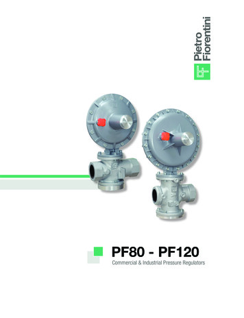
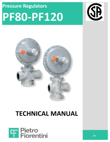
Pressure RegulatorsDocument classified as: 2 - Company ConfidentialPF80-PF120TECHNICAL MANUALUS
PF80 & PF120Basic versionINLET PRESSUREOUTLET PRESSURE2MT 313 – EN ed.2018 (Rev.M)
GENERAL WARNINGSThe regulator and accessories described in this manual are installed in systems under pressure and supply and control flammablegases (e.g. natural gas).WARNINGS FOR THE INSTALLATION AND OPERATING PERSONNELBefore performing the installation, start-up or maintenance, you must: review the safety procedures applicable to the installation siteobtain the necessary training to operate and maintain the equipment, when requiredbe equipped with the necessary personal protective equipment (helmet, goggles, etc.make sure that the area where the equipment operates is equipped with the required safety equipment and has thenecessary safety signs and notifications.PACKAGING / TRANSPORT / STORAGEThe packaging materials used for transporting the equipment and the related spare parts have been designed and manufactured toavoid damages during normal transport, storage, and related handling. Therefore, the equipment and spare parts must be kept in theirrespective original packages until their installation in the destination site. When the packages are opened, it is necessary to verify theintegrity of the materials therein contained. In case of damages, report the detected damage and please keep the original crate or boxto allow the proper inspections of damages that may have occurred.The storage of the equipment, even after its use, must occur in a moisture free environment and away from sources of light and withinthe temperature limits stated on the devices rating plate.HANDLINGThe handling of the regulator and its components must be performed using lifting means that are suitable for the weight to be lifted(lifting capacity and functionality) to avoid damage to the regulator such as bumps, impacts and local stresses.When necessary, the handling of the regulator must be performed using the lifting points shipped with the equipment (lifting rings).The use of motorized powered lift should only be operated by authorized personnel.INSTALLATIONThe installation of the pressure regulator must occur in compliance with company’s codes, local codes and standards (laws orregulations) in force in the location of the installation.Natural gas regulating stations must be designed and installed so they comply with the required laws or regulations in force in theplace of installation. The installation must be in compliance with such standards minimizes the risk of fire and the formation of potentiallyhazardous atmospheres.If the single regulator is not provided with built in overpressure protection devices, it must be installed making sure that the operatingpressure of the installation in which it is installed does not exceed the value of the allowable maximum pressure (PS).The user shall therefore, when he/she deems it necessary, provide for the installation on the assembly of suitable pressure limitationsystems. Make sure you equip the station with suitable relief or bleed systems to be able to discharge the pressure and the gascontained in the station before proceeding with any inspection and maintenance.Should the installation of the equipment require the installation on site of compression fittings and these should be installed followingthe instructions provided by the manufacturer of the fittings. The selection of the fittings must be compatible with the use specified forthe equipment and with the plant specifications, when foreseen.STARTUP (COMMISSIONING)The startup must be carried out by suitably trained personnel.During the startup, all personnel not required for the startup must be kept away and the area must be properly marked (signs, barriers,etc.).Verify that the regulator and its accessory set points are the ones required and ordered from the factory. If necessary, you may needto adjust the required values as shown for later in this manual.During the startup, there may be a risk of a discharge to the atmosphere of flammable or noxious gases must be reviewed.For installation on natural gas distribution systems, it is necessary to consider the risk of formation of a (gas/air) explosive mix withinthe piping.COMPLIANCE WITH ANSI B109.4 CERTIFIED BY CSAThe PF80 and PF120 regulators are certified according ANSI B109.4, regulators with size Max 1-1/4” NPT and Outlet Pressure 7” w.c.are in compliance with CSA 6.18-02 and ANSI B109.4. For the other models and outlet pressure, all the tests were performed inreference to the CSA 6.18-02 and ANSI B109.4 standard.3MT 313 – EN ed.2018 (Rev.M)
1.0INTRODUCTIONThis manual is intended to supply essential information on the installation, startup, disassembly, re-assembly, and maintenance ofthe regulators PF80 and PF120.The manual will also provide you with a brief description of the main features of the regulator and itsaccessories.1.1MAIN FEATURESThe pressure regulator PF80 and PF120 is a pressure regulator designed for filtered, cleaned gases. PF80 and PF120 are fail openregulators and will open in case of: Breakage of the main diaphragm, failure of the valve or seat assembly, damage to the lever mechanismLack of set point pressure signal.The main features of this regulator are: 1.1.1Design inlet pressure: up to 125 PSIGAmbient temperature: -20 F to 150 F (-28 C to 65 C)Flowing gas operating temperature: -14 F to 140 F (10 C to 60 C)Inlet pressure range: 5 to 125 PSIGControl head Maximum Outlet Pressure: PF80 10 PSIG, PF 120 5 PSIGOutlet pressure range: PF 80 7” w.c. - 10 PSIG, PF120 7” w.c. - 5 PSIGAccuracy class:üFix Factor Billing (ANSI b109.4)§ 2”/-1” w.c. with Set point 14” w.c.;§ 2” w.c. with 14” w.c. Set Point 1 PSIG§ 1% Abs with 1 PSIG Set Point 2 PSIGüGeneral Application: 10% GaugeINTEGRAL STRAINERAll PF80 and PF120 models can be equipped with a removable built-in 300-micron strainer to prevent foreign particles, like weldingslag or PE shavings, from entering the orifice and valve seat chamber and preventing lockup. The strainer also provides protection toall optional integral overpressure protection devices as well as downstream customer system. The strainer can easily be accessedwithout removing the regulator body from the piping, cleaned and replaced, if necessary.4MT 313 – EN ed.2018 (Rev.M)
1.2OPERATION OF THE CONTROL HEADWithout pressure and with loaded setting spring, the valve (211) is kept in the open position by the connection of the stem (201) to thelever mechanism (305). The outlet pressure (Pd) is controlled by the comparison between the load of the spring (328) and the forcethat the outlet pressure exerts on the diaphragm (322).The weight of the regulators components and inlet force acting on the valve are considered in the calculation of the balanced forces tooperate the regulator. With this design as your inlet pressure changes it does not affect the balance of the valve (211), since the same- given the presence of the hole A - finds itself between two equal pressures acting on equal surfaces.The movement of the diaphragm (322) controls the lever system (305) which is connected to the stem (201) and the valve (211). Thevalve is provided with a vulcanized rubber gasket to assure a perfect tightness with the flow rate is zero.During operation when the outlet pressure (Pd) decreases, the force it exerts under the diaphragm (322) becomes lower than the loadof the spring (328); causing the diaphragm to lower through the lever (305). The valve (211) to move away from the valve seat (102).Consequently, the gas flow rate increases until the initial set point pressure value is restored.When the outlet pressure starts to increase, the force exerted on the diaphragm (322) exceeds the load of the spring (328). Then thevalve is shifted toward the closed position, letting the outlet pressure return to the set point value. Under normal operating conditions,the valve (211) is positioned in such a way as to maintain the pressure (Pd) around the chosen set point value. The set point pressurecan be adjusted by turning the internal spring adjustment nut (318) clockwise to increase the pressure and counterclockwise todecrease the pressure.Figure 1: Control Head5MT 313 – EN ed.2018 (Rev.M)
TOKEN INTERNAL RELIEF VALVE (IRV)The token IRV is shown in fig. 3. and is not a full relief device to be used as an OPP device. Its function is to protect the regulatoragainst increases in the outlet pressure. This is used to relieve an increase in outlet pressure, such as thermal build up from sitting inthe sun or from a quick acting on-off boiler, which may cause the slam shut to trip.This token IRV diaphragm plate (323) is normally seated against the upper cover. If the set pressure increases to the set point of theIRV, it overcomes the load of the IRV spring (329), the IRV which opens the IRV valve, relieving the pressure caused by the abruptpressure increase.If the IRV is not needed it can be deactivated as shown in fig. 2 below. You will need to install 2 O-rings on the stem assembly to blockthe path of the gas deactivating the IRV.6MT 313 – EN ed.2018 (Rev.M)
1.3SET POINT SPRINGS FOR THE REGULATORTable 1.1 shows the set point ranges of the different available springs.Control Head PF 120 Maximum Outlet Pressure 7.25 PSIG, PF 80 head is 10 PSIG. In case of a single regulator supplied without built inoverpressure Pietro Fiorentini protection device (SSV, IMD or IFM), the regulator shall be protected with a secondary means ofoverpressure protection per does DOT §192.740 & NFPA 54 5.9.3.1 standard. The over pressure protection must be provided per codecapable of limiting the downstream pressure to the system.SPRINGS FOR PF �� – 11” w.c.US64470301GIYELLOWLP12”– 16” w.c.US64470302VIVIOLETLP0.6 – 1.2 PSIGUS64470262ARORANGEMP1.3 – 2.4 PSIGUS64470398AZLIGHT BLUEMP2.5 – 4.2 PSIGUS64470408ROREDMP4.3 – 5 PSIGSPRINGS FOR PF 80CodeColorUS64470068GIYELLOWLP6.8” – 9.6” w.c.US64470139NEBLACKLP10” – 14.1” w.c.US64470071GRGREYLP0.9 – 1.5 PSIGUS64470141VEGREENMP1.5 – 2.4 PSIGUS64470329AZLIGHT BLUEMP2.5 – 5.3 PSIGUS64470144VIVIOLETTR5.4 – 10.2 re installing the regulator, it is necessary to make sure that: the regulator can be inserted in the existing space provided and provides sufficient area for performing maintenanceoperations (see overall dimensions in table 2.1)the inlet and outlet piping is level and aligned and can support the regulator weight (see table 2.2)the inlet/outlet connections of the regulator are clean from any residual impurities such as welding scraps, sand, paintresidues, water, etcthe regulator itself has not been subject to any damages during transportThe recommended installations are shown in fig. 4.Figure 47MT 313 – EN ed.2018 (Rev.M)
Table 2.1: Overall dimensions in inches (fig. 6)CodeDNA*B**C**DEFMPF80 basic1-1/4”; 1-1/2”; 2” NPT6.6”10.2”2.6”7.3”7.0”1/4”PF80 IMD1-1/4”; 1-1/2”; 2” NPT6.6”10.2”4.25”7.3”7.0”1/4”PF80 IFM1-1/4”; 1-1/2”; 2” NPT6.6”10.2”10.3”7.3”7.0”1/4”PF80 SSV1-1/4”; 1-1/2”; 2” NPT6.6”10.2”8.2”7.3”7.0”1/4”PF120 basic2” 120 IMD2” NPT7.6”15.4”6.1”11.0”10.1”1/2”PF120 IFM2” NPT7.6”15.4”15.5”11.0”10.1”1/2”PF120 SSV2” /4”* Flanged version: A dimension equal to 10”** Disassembling requires 3” more than overall dimension on PF120 and 2” on PF80, except in case of blind flangeTable 2.2: Weights in poundsCodeBasicIMDIFMSSVPF80 1-1/4"; 1-1/2"; 2"13.518.118.114.8PF120 2"26.036.436.427.6PF120 2" flanged34.845.245.236.4Figure 6: Overall dimension8MT 313 – EN ed.2018 (Rev.M)
2.2CONNECTING THE EQUIPMENTThe Pietro Fiorentini regulators series can be equipped with: internal sensing lineexternal sensing lineexternal sensing line (monitor version)The connections between the equipment and the piping have to be carried out using a stainless-steel tubing, having a minimumdiameter of 3/8” OD.RegulatorExternalsensing line Pressure gaugeRelief valveRegulatorRelief valveOn-off valvePressuregaugeOn-off valveExternalsensinglineFigure 7: Installation diagramThe regulator must be installed in the line the arrow is position on the body in the direction of the gas flow. To obtain a good regulationset point, it is essential that the position of the outlet pressure sensing points and the gas speed at the sensing point meet the valuesgiven in table 2.3.The single regulator must be protected from over pressurization with a built in or a secondary protection device.To prevent impurities and condensation from building up in the pressure sensing tubes, please make sure of the following: the tubing must always be positioned on a descending slope towards the connection of the outlet piping, with a slope ofabout 5 - 10%;tubing tapped connections are always to be welded on the upper part of the piping itself and be a minimum of ½” and thehole on the piping shall not show any burrs or projections towards the internal side. Use full port ball valves if valves areinstalled in the sensing lines.To avoid breaking the pipe or regulator, it is recommended to provide for the following: the equipment shall be installed with all codes in force and the good piping practicesthe equipment shall be supported properly with no external loads acting on the regulatorthe equipment shall be provided with adequate protection and grounding means to protect it against stray currents andelectrostatic potential differentialsthe equipment shall be used within the pressure limitations indicated on the rating plateFOR OPTIMAL PERFORMANCE, gas speed should not exceed the following values:Vmax 82 ft./s for 21.75 Pd 72.50 PSIGVmax 65 ft./s for 7.25 Pd 21.74 PSIGVmax 49 ft./s for Pd 7.24 PSIGTable 2.39MT 313 – EN ed.2018 (Rev.M)
3.0MODULARITYThe modular concept of the PF80 - PF120 series allows the possibility of installing the fol
COMPLIANCE WITH ANSI B109.4 CERTIFIED BY CSA The PF80 and PF120 regulators are certified according ANSI B109.4, regulators with size Max 1-1/4” NPT and Outlet Pressure 7” w.c. are in compliance with CSA 6.18-02 and ANSI B109.4. For the other models and outlet pressure, all the tests were performed in