Transcription
PF80 - PF120Commercial & Industrial Pressure Regulators
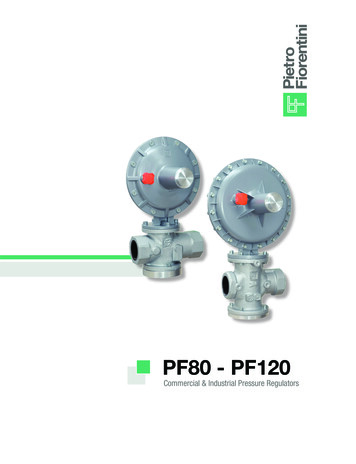
PF80 - PF120OVERVIEWThe PF80 & PF120 spring loaded direct-acting natural gas pressure regulators are suited for commercial and industrialapplications requiring low and medium delivery pressures. The modular design allows for easy adaptation of multipleoptional overpressure protection devices to fit almost any application requirement.Features Balanced valve design Stable outlet pressure independent of inlet pressure variation High turndown ratio easily serves varying loads Single orifice simplifies sizing without impacting inlet pressure limitation Internal strainer protects the orifice and seat from foreign debris Multiple body sizes to fit design requirements Outlet pressure ranges from 6” w.c. to 10 PSIG Environmentally-friendly overpressure protection options that minimize or eliminate large volumes of gas from beingemitted to the atmosphere in the event of an abnormal conditionFig. 1PF80 - (Basic version)Fig. 2IMD - (Independent Monitoring Device)Fig. 3SSV - (Slam-Shut Valve)Fig. 4IFM - (Independent Full Monitor - IFM)2
PRODUCT SPECIFICATIONSSpecifications Maximum Inlet Pressure:125 PSIG Outlet Pressure Range:7” w.c. to 10 PSIG Ambient Temperature Range:-20 F 150 F Flowing Gas Temperature Range:-4 F 140 F Body Size:PF80 1¼” NPT; 1½” NPT; 2” NPTPF120 1½” NPT (Pending); 2” NPT2” Flanged Spring Case Vent Connection:½” NPT Orifice SizePF80 3/4”PF120 1½” CG ValuesPF80: 245PF120: 818Materials: Body:Ductile Iron Diaphragm Case:Aluminium Diaphragm:Nitrile Rubber Orifice:Brass O-rings:NitrileIndustry standards: ANSI B109.4 ANSI Z21.803Providing Solutions for Oil and Gas
BALANCED VALVE DESIGN (Fig.5 Item #1)PF80 and PF120 regulators are spring loaded self-operated regulators that incorporate a balanced valve design. Thebalancing valve allows an opposite force equal to the inlet pressure to be applied on the back side of the orifice’s seatdisk. This feature improves the consistency of the outlet pressure setting as inlet pressure fluctuates, and provides highturndown ratio across a wide flow range.INTEGRAL STRAINER (Fig.5 Item #2)All PF80 and PF120 models are equipped with a removable internal 300 micron strainer to prevent foreign particles,such as weld slag or PE shavings, from entering the orifice and seat disk chamber and preventing lockup. The straineralso provides protection to all optional integral overpressure protection devices as well as downstream customer assets.The strainer can easily be accessed without removing the regulator body from the piping, cleaned and replaced, ifnecessary.TOKEN RELIEF VALVE (Fig.5 Item #3)All PF80 and PF120 regulator models have an optional token relief valve that discharges a small volume of gas to theatmosphere when the regulator exceeds the outlet pressure set point. During no-flow conditions, thermal expansion ofthe gas can cause downstream static pressure to build up. The token relief valve will prevent downstream pressure fromrising, and if equipped, prevent nuisance tripping of the SSV.OUTLET PRESSURE SENSING (Fig.5 Item #4)All PF80 and PF120 regulators can sense downstream pressure internally (4a), externally (4b), or by using both. Internalsense versions have a sense line built into the outlet of the regulator body. Externally sensed versions require the internalsense line to be plugged, and use a secondary external sense line connected to the lower diaphragm case. When usingthe external sense configuration without plugging the internal sense line, the higher pressure of the two will provide thecontrol pressure to the lower diaphragm. This can be used to improve response in applications where the load changesquickly.34a324b241Fig.5
SPRING RANGE TABLESFeatures of the springs for PF120ColorHeadPressure RangeBLACK US64470382NEYELLOW US6447031GIVIOLET US64470302VIORANGE US64470262ARLIGHT BLUE US64470398AZRED US64470408RORED US64470408ROBPBPBPMPMPMPTR7” – 11” w.c.12”– 16” w.c.0.6 – 1.2 PSIG1.3 – 2.4 PSIG2.5 – 4.2 PSIG4.3 – 7.3 PSIG7.3-10.2 PSIGTab.1Features of the springs for PF80ColorYELLOW US64470068GIBLACK US64470139NEGREY US64470071GRGREEN US64470141VEBLUE US64470338BLVIOLET US64470144VIHeadPressure RangeBPBPBPMPMPTR6.8” – 9.6” w.c.10” – 14.1” w.c.0.9 – 1.4 PSIG1.5 – 2.4 PSIG2.5 – 5.3 PSIG5.4 – 10.2 PSIGTab.25Providing Solutions for Oil and Gas
INDEPENDENT MONITORING DEVICE - IMDThe IMD is an effective overpressure protection safety device (OPP) designed to limit downstream pressure buildupin case of regulator catastrophic failure such as a seat cut diaphragm, or lever disconnect. When a failure occurs, the IMDoperates on the inlet side or the orifice to limit downstream pressure.Since the IMD is a separate and independent monitor from the main regulator, it will function in the event of a catastrophicfailure on the main regulator.When the IMD is functioning or in lock-up, a small amount of gas will bleed continuously to the atmosphere througha small port in the IMD (less than 15 CFH). This serve as an alert that the regulator is functioning under an abnormalcondition.It is recommended you do not use the token relief valve option when using the IMD.Fig.6IMD - (Independent monitoring Device)IMD PerformanceIMD Activated Vent Flow RateRegulatorSetRangeIMD version7” w.c.7”w.c. – 1PSIG7”w.c. – 2 PSIG7”w.c. – 5 PSIGIMD-1IMD-2IMD-5IMD-7MaximumIMD peakActivationPressure0.9 PSIG1.8 PSIG3.9 PSIG6.9 PSIGIMD PressureControlRange *IMD Lock-uppressureStandardversionVent limitedversion0.5 - 0.7 PSIG1.2 - 1.7 PSIG2.4 - 3.7 PSIG5.5 - 6.5 PSIG0.9 PSIG1.8 PSIG3.9 PSIG6.9 PSIG 15 CFH 15 CFH 15 CFH 15 CFH 1 CFH 1 CFH 2.5 CFH 2.5 CFHTab.3* Depending on flow rate and inlet pressure.6
SLAM SHUT VALVE - SSVThe SSV is an overpressure protection safety device designed to shut off the gas flow under abnormal downstreampressure conditions. The SSV can be configured to operate when any of three conditions are met: overpressure,underpressure, or both over/under pressure.To help ensure that the abnormal condition has been properly corrected, the SSV must be manually reset.The internal bypass valve simplifies resetting by equalizing internal pressure, thus eliminating the need for anyother tools or piping. SSV set-points are field adjustable.It is highly recommended to use the optional token relief valve wen using the SSV.Fig.7SSV - (Slam-Shut Valve)Shut-Off Device Model SSV PerformanceWorkerSet PointMINIMUM SUGGESTED SET-POINT7” w.c.2 PSIG5 PSIG10 PSIG (Pending)15” w.c.3 PSIG7 PSIG12 PSIGTab.4Features of the springs for SSV PF80 – PF120ColorSSV HeadPressure RangeRED US64470112ROGREY US64470115GRYELLOW US64470116GIWHITE US64470051BIBLUE US64470057BLBPBPMPMPMP14” – 20” w.c.0.7 – 2.5 PSIG2.6 – 3.9 PSIG4 – 6.9 PSIG7 – 17 PSIGTab.57Providing Solutions for Oil and Gas
INDEPENDENT FULL MONITOR - IFMThe IFM is an overpressure protection safety device that will precisely take over outlet pressure control when an abnormal eventoccurs in main worker regulator. In this configuration, the gas flows through the monitor first, and then through the worker(or operator) regulator. The monitor regulator outlet pressure set-point must be set higher than the worker which will allow fullflow through to the worker regulator under normal operation. In the event of an abnormal condition in the worker regulator, themonitor will resume accurate pressure control at a slightly higher outlet pressure set-point.Since the two control actuators are externally tied together, regulator operation does not require an external sense line, althoughthe control actuators can be tied to a common external sense connection.If an external sensing line is used then it is recommended to plug the internal sense line.Fig.88IFM (Independent Full Monitor)
MONITORA monitor is an emergency pressure regulator that is usually upstream from the worker regulator. In an abnormal eventwhen the worker regulator is unable to maintain downstream pressure from exceeding the set point, the monitor willperform the function of the worker regulator at a set point slightly higher than the worker regulator.An external sensing line is required in upstream monitor configurations, and the internal sense line must be plugged.Sensing lineFig.9Typical remote sense connection for independent applicationsFig. 109Providing Solutions for Oil and Gas
SIZING THE PRESSURE REGULATORThe following charts are provided in order to simplify the sizing of the regulators. Select your inlet pressure, required outletpressure and then select the given flow in the tables.NOTE: The flow value in the following tables are actual maximum reccommended flows for the regulator withall the option devices and no safety factor is necessary when sizing the regulator.Capacity TablesOutlet pressure (psig) 7”WC ( 2”WC/-1”WC)Inletpressure1 408,500607,00072,57,0001007,0001257,000* Flow Rate (SCFH)PF80*1 ,0008,0008,0008,000Outlet pressure (psig) 14”WC ( /-2”WC)Inletpressure1 408,500607,00072,57,0001007,0001257,000* Flow Rate 9,00025,00025,00025,00025,000Tab.6Outlet pressure (psig) 1 PSIG ( /-1% ABS; /- 0.155 PSIG)InletPF80*PF120*pressure1 ¼”1 ,00013,00027,250* Flow Rate (SCFH)Tab.8PF80*1 Outlet pressure (psig) 2 PSIG ( /-1% ABS; /- 0.165 PSIG)InletPF80*PF120*pressure1 ¼”1 ,00012,00027,250* Flow Rate (SCFH)Tab.910
Capacity TablesOutlet pressure (psig) 5 PSIG ( /-1% ABS; /- 0.197 50* Flow Rate (SCFH)Tab.10Outlet pressure (psig) 5 PSIG ( /-10% Gauge; /- 0.5 0030,000* Flow Rate (SCFH)Tab. 11Outlet pressure (psig) 10 PSIG ( /-10% Gauge; /- 0.1 50042,000* Flow Rate (SCFH)Tab. 12TYPICAL CONNECTION DIAGRAMSThe following examples are provided as a recommendation to get the best performance from the PF80 & PF120regulators. Additional control head orientation are available on request.Flow Horizontal Left-RightFlow Horizontal Right-LeftFlow Vertical Bottom Up11Flow Vertical Top-DownProviding Solutions for Oil and Gas
Available Configurations:PF80PF120 PF80PF120MODEL8PF802PF120BODY CONNECTIONS A1-1/4” NPT B1-1/2" NPT C2" NPT D2"-125# FF Flange PF80PF120 01STD/A: Basic Regulator, Internal Sense, Token Relief 02STD/A: Basic Regulator, Internal Sense, No Token Relief 03STD/M: Basic Regulator, External Sense Only, Token Relief 04STD/M: Basic Regulator, External Sense Only, No Token Relief 05IMD: STD/A with Independent Monitoring Device, No Token Relief 06IMD/VL: STD/A with Vent-Limiting Independent Monitoring Device, No Token Relief 07IFM: STD/A (No Token Relief) x STD/M (Token Relief) Independent Full Monitor 08SSV/A: STD/A with Slam Shut Valve, Token Relief 09SSV/M: STD/M with Slam Shut Valve, Token Relief 10SSV/A: STD/A with Slam Shut Valve, no Token Relief 11SSV/M: STD/M with Slam Shut Valve, no Token ReliefPF80PF120CONFIGURATIONINTERNAL STRAINER AStrainer BNo StrainerPF80PF120SPRING RANGE 11BP/80/Yellow: 6.8" - 9.6" WC 12BP/80/Black: 10" - 14.1" WC 13BP/80/Grey: 0.9 - 1.4 PSIG 14MP/80/Green: 1.5 - 2.4 PSIG 15MP/80/Blue: 2.5 - 5.3 PSIG16TR/80/Violet: 5.4 - 10.2 PSIG 21BP/120/Black: 7" - 11" WC 22BP/120/Yellow: 12" - 16" WC 23BP/120/Violet: 0.6 - 1.2 PSIG 24MP/120/Orange: 1.3 - 2.4 PSIG 25MP/120/Light Blue: 2.5 - 4.2 PSIG 26MP/120/Red: 4.3 - 7.3 PSIG 27TR/120/Red: 7.3 - 10.2 PSIG Tab.1312
Available Configurations:PF80PF120OPP RANGE 11 12IFM BP/80/Black: 10" - 14.1" WC 13IFM BP/80/Grey: 0.9 - 1.4 PSIG 14IFM MP/80/Green: 1.5 - 2.4 PSIG 15IFM MP/80/Blue: 2.5 - 5.3 PSIG 16IFM TR/80/Violet: 5.4 - 12.0 PSIG 21IFM BP/120/Black: 7" - 11" WC 22IFM BP/120/Yellow: 12" - 16" WC 23IFM BP/120/Violet: 0.6 - 1.2 PSIG 24IFM MP/120/Orange: 1.3 - 2.4 PSIGIFM BP/80/Yellow: 6.8" - 9.6" WC 25IFM MP/120/Light Blue: 2.5 - 4.2 PSIG 26IFM MP/120/Red: 4.3 - 7.3 PSIG 27IFM TR/120/Red: 7.3 - 12.0 PSIG 31SSV - BP/Red: 14" - 20" WC 32SSV - BP/Grey: 0.7 - 2.5 PSIG 33SSV - MP/Yellow: 2.6 - 3.9 PSIG 34SSV - MP/White: 4 - 6.9 PSIG 35SSV - MP/Blue: 7 - 17 PSIG 41IMD - 1 42IMD - 2 43IMD - 5 44IMD - 7 99No OPPPF80PF120 POSITIONAVBU: Vertical, Bottom-Up BVTD: Vertical, Top-Down CHLR: Horizontal, Left-Right DHRL: Horizontal, Right-LeftPF80PF120 TEMPERATUREAAmbient Temperature -20 F to 150 FTab.1413Providing Solutions for Oil and Gas
BASIC VERSION - OVERALL DIMENSIONSOverall dimensions in inchesAA1BCDFMInletOutletPF 80PF 1206.6”/10.2”2.6”17.3”7.0”1/4” NPT1-1/4”; 1-1/2”; 2”NPT1-1/4”; 1-1/2”; 2”NPT7.6”10.015.4”3.9”11.0”10.1”1/2” NPT2” NPT2” NPTTab.15
ANSI B109.4 ANSI Z21.80 PRODUCT SPECIFICATIONS. 4 BALANCED VALVE DESIGN (Fig.5 Item #1) PF80 and PF120 regulators are spring loaded self-operated regulators that incorporate a balanced valve design. The balancing valve allows an opposite force equal to the inlet pressure to be applied on the back side of the orifice’s seat disk. This feature improves the consistency of the outlet .