Transcription
Int. J. Electrochem. Sci., 7 (2012) 9074- 9084International Journal arison of Photocatalytic Activity and Cyclic Voltammetryof Zinc Oxide and Titanium Dioxide Nanoparticles towardDegradation of Methylene BlueS.O. Fatin.1, H.N. Lim2,*, W.T. Tan2, N.M. Huang11Low Dimensional Materials Research Centre, Department of Physics, Faculty of Science, Universityof Malaya, 50603 Kuala Lumpur, Malaysia.2Department of Chemistry, Faculty of Science, Universiti Putra Malaysia, 43400 UPM Serdang,Selangor, Malaysia.*E-mail: janet limhn@science.upm.edu.myReceived: 15 July 2012 / Accepted: 31 August 2012 / Published: 1 October 2012We report on the photocatalytic degradation of methylene blue (MB) solution using commercial ZnOand TiO2 (P25) photocatalysts, in the form of slurry and immobilized on glass slides, under ultraviolet(UV) and solar irradiations. The average particle sizes of ZnO and P25 were 100 nm and 30 nm,respectively. Under both the irradiations, the photocatalytic activities of ZnO and P25 slurry resulted inbetter photocatalytic performance than the immobilized photocatalysts. Interestingly, ZnO showedbetter degradation capability in comparison to P25 under the solar irradiation. This result revealed thatsolar light provided a good source of energy to degrade MB in the presence of ZnO. The cyclicvoltammetry analysis suggested that the photocatalysts possessed different mechanisms for thedegradation of MB. The potential of immobilizing photocatalysts without compromising theirperformance may lead to easy handling of these materials, resulting in expanding their applications, forexample, as a photoanode for photoelectrochemistry.Keywords: ZnO; TiO2; solar; thin film1. INTRODUCTIONThe removal of organic pollutants in waste water using semiconductor photocatalysts hasattracted a lot of attention as an important issue on environmental protection [1-5]. Photocatalyticoxidation is an economical process owing to the fact that it involves only a photocatalyst and lightsource [6]. This process does not yield toxic intermediate product, making it suitable for cleaningwater environment that contains low to medium contaminants concentration [7]. Under the
Int. J. Electrochem. Sci., Vol. 7, 20129075illumination of light that have energies higher than the photocatalyst band gap, the electrons from thevalence band will be excited to the conduction band, therefore, creating the negative electron-positivehole pairs (). Thepairs will initiate a series of reactions and produce hydroxylradicals,, and superoxide radical anions,, when the photocatalyst is in contact with water.With the radicals on the photocatalyst surface, the organic contaminants are oxidized at or near to thephotocatalyst surface [8].Titanium dioxide, particularly P25, is found to be the most efficient photocatalyst forphotodegradation of pollutants due to its properties which are suitable band gap (3.2 eV), photo stableand nontoxic [9]. Besides TiO2, zinc oxide (ZnO) has also shown promises as an innovative andrelatively low-cost photocatalyst. ZnO is an n-type semiconductor that possesses suitable band gap(3.17 eV), large exciton binding energy (60 meV) and high electron mobility [10].Photocatalysis requires the mixing of the powder photocatalyst into the pollutant water,resulting in slurry suspension of photocatalyst. It is almost impossible to obtain powder-free waterafter the photocatalysis process, making it an impractical solution to getting pristine water [11]. Thisproblem limits its practical application, following the need of centrifugation and consumes time forsettlement. Therefore, many attempts have been made to immobilize the catalyst particles on a rigidsupport by different approaches [12]. Even though immobilized photocatalyst has lower efficiencywhen compared with photocatalyst in the slurry form because of the smaller interface surfaceavailable, the disadvantage is outweighed by the practicality of reusing immobilized photocatalyst,which makes it suitable to be applied for continuous water treatment. Hence, long-term attachment ofphotocatalyst on the support must be guaranteed so that it can be reused in the next treatment [13].Many researchers reported using UV irradiation as an energy source in the photocatalyticdegradation of organic compounds [14-16]. The drawbacks of UV light are that it is hazardous, mayaffect the photocatalyst decomposition and expensive because of large input of electric power togenerate radiation [17]. Solar light consists of only 5% of the total radiation that possesses theoptimum energy for the band gap excitation of electrons; however, in tropical countries like Malaysiawhere intense sunlight is abundant and available throughout the years, it is a safe and cost-effectivesource.In this paper, the phocatalytic behavior of P25 was compared against ZnO in the forms ofslurry and immobilized on a glass slide under the illumination of UV and solar lights for thedegradation of MB solution, which is reported for the first time. Moreover, this is the first ever attemptin which cyclic voltammetry analysis is used to determine the degradation mechanism ofphotocatalysts. This fundamental and preliminary work is important to gauge if the performance ofimmobilized photocatalyst would be compromised compared to that of the slurry form. Moreover, thiswork is able to assess if the solar energy is comparable to UV for the photocatalysis process. This workcould lead to more investigations on photoelectrochemistry, in which immobilized photocatalyst onindium tin oxide (ITO) coated glass acts as a photoanode.
Int. J. Electrochem. Sci., Vol. 7, 201290762. EXPERIMENTAL2.1. MaterialsZinc oxide was purchased from Aldrich (99%, St. Louis, USA), titanium (IV) oxide AeroxideP25 was purchased from Acros Organics (99.5%, New Jersey, USA), methylene blue was purchasedfrom Systerm (Selangor, Malaysia) and all the solutions were prepared using distilled water.2.2. Preparation of immobilized photocatalystsZnO slurry was prepared by mixing ZnO powder with distilled water. The ZnO slurry was thensmeared onto a glass slide using the doctor blade’s method to produce immobilized ZnO. Thedimension of the coating on the glass slide for the solar and UV irradiation test was fixed at 4 cm 2cm with a mass of 12 mg. Then, the coating was calcined at 450 C for 2 h. The adherence of thephotocatalyst on the glass slide was tested by immersing the film in stirred water for 3 days, in whichno flotation was observed. Immobilized P25 was prepared using the same procedure. The same amountof photocatalyst, used for immobilization, was calcined independently at 450 C for 2 h, which wassubsequently employed in the form of slurry for photocatalytic evaluation.2.3. CharacterizationCrystalline phase was determined using a PanAlytical Empyrean X-Ray Diffractometer (XRD),employing a scanning rate of 0.12 C/min in a 2θ range from 20o to 70o with Cu Kα radiation (λ 1.5418 Ǻ). The morphologies of ZnO and TiO2 photocatalysts were obtained using a FEI NovaNanoSEM 400 Field Emission Scanning Electron Microscope (FESEM). The change in thephotodegradation of the MB solution was determined using an Ultraviolet-Visible SpectrophotometerEvolution 300 (UV-Vis) by measuring its absorbance spectra within 500 nm to 750 nm.2.4. Photocatalytic activityThe photocatalytic activities were evaluated by decolorization of 1.5 ppm of MB solution. ForUV irradiation, the immobilized photocatalyst was placed inside a beaker containing 100 ml of MBsolution. Then, the beaker was placed inside an Ultraviolet Crosslinker (UVP-CL-1000, Cambridge)with 5800 μW/cm2 intensity which was stacked onto a magnetic stirrer. The beaker was exposed underthe UV irradiation for 30 m with a stirring rate of 200 rpm. The distance between the photocatalyst andthe light source was fixed at 13 cm. In the case of slurry photocatalyst, the MB solution was separatedfrom the photocatalyst by centrifugation at 4000 rpm. The experiment was repeated for solarirradiation using a solar simulator Oriel Instrument (AM 1.5; Newport Corporation, Irvine, CA, USA)with 8220 μW/cm2 intensity from 150 W Xe lamp. Both the irradiations were repeated without thepresence of photocatalysts in the MB solution.
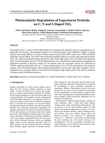
Int. J. Electrochem. Sci., Vol. 7, 201290772.5. Cyclic VoltammetryCyclic voltammetry (CV) study was performed on a VersaSTAT 3 potentiostat (AmetekPrinceton Applied Research, Oak Ridge, TN) using a conventional three-electrode system. Theworking electrode was a photocatalyst powder-modified glassy carbon electrode (GCE) (3 mmdiameter, Princeton Applied Research), the reference electrode was an Ag/AgCl (in 3M NaCl)electrode, and the counter electrode was a platinum wire. The GCE was polished successively using0.1 μM of alumina slurry on a micro-cloth polishing pad (Buehler, Lake Bluff, 1L), and rinsedthoroughly with distilled water between each polishing step. For preparation of photocatalyst-modifiedGCE, the bare GCE was tapped onto the photocatalyst powder. The electrochemical response of 1.5ppm of MB solution was investigated in 0.1 M of KCl supporting electrolyte by cyclic scanningbetween -1.0 V and 1.0 V at a scan rate 50 mVs-1. All the voltammetric measurements were carried outat room temperature. The photoactivity of ZnO and P25 against the MB solution was measured byexposing the reactant to solar light from the solar simulator for 2 h. The data was recorded every 20min.3. RESULT AND DISCUSSIONThe structural characterization and electron microscopy observation of the photocatalysts are toensure that their crystallinities and morphologies remained the same after being subjected to the heattreatment for their immobilization on glass slides. Fig. 1a shows that the ZnO powder can be wellindexed to the hexagonal wurtzite structure [18]. The absence of other impurity peaks indicates theclear crystallinity of the ZnO powder. Meanwhile, Fig. 1b shows the XRD patterns of P25 havingpeaks indicative of the reflections for anatase and rutile with no other peaks of impurity [19]. The finalforms of the photocatalysts experienced insignificant differences when exposed to the heat treatment,suggesting that ZnO and TiO2 are stable enough to retain their characteristic structures despite theharsh condition.Figure 1. XRD patterns of (ai) calcined ZnO, (aii) ZnO film, (aiii) ZnO pure powder, (bi) calcine P25,(bii) TiO2 film, and (biii) TiO2 pure powder.
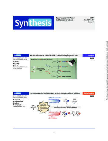
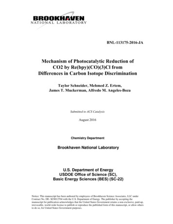
Int. J. Electrochem. Sci., Vol. 7, 20129078Fig. 2 shows the SEM images of the nanostructures of ZnO and P25. The morphologies of bothZnO and P25 remained unchanged after calcination regardless of whether they were in the powderform or immobilized on glass slides. The size of ZnO is 100 nm, which is about three times larger thanthat of P25.Figure 2. SEM images of (a) ZnO powder after calcination, (b) immobilized ZnO after calcinations,(c) P25 powder after calcination, and (d) immobilized P25 after calcination.Fig. 3 exhibits that the absorbance spectra of the MB solution have a maximum absorptionwavelength at approximately 660 nm. Fig. 3a portrays the absorbance spectra of the MBphotodegradation in the absence of photocatalyst. After 30 min of illumination, the peak under the UVand solar irradiations reduced compared with the initial concentration. This is due to photolyticreaction of MB induced by the absorption of UV light and solar light, which leads to the degradation ofMB [20]. The peak for UV irradiation is lower than the peak for solar irradiation, showing that thephoton energy of UV irradiation is higher than that of solar irradiation.Fig. 3b exhibits the absorbance spectra of the MB degradation under the UV irradiation. TheZnO and P25 slurries were found to be more efficient in photocatalyzing the MB solution comparedwith the immobilized counterparts. The peaks of the MB solution with P25 are lower than those of
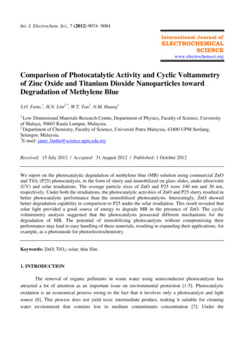
Int. J. Electrochem. Sci., Vol. 7, 20129079ZnO, both in the slurry and immobilized forms. The enhanced photocatalytic performance of P25 iscontributed by its ability to strongly absorb UV rays due to its high band gap energy [21, 22]. It hasbeen reported that the photodegradation capability of ZnO is weaker than P25 under the illumination ofUV light [23].Fig. 3c portrays the absorbance spectra of MB degradation under the solar light irradiation.Similarly, the slurries of ZnO and P25 were found to be better in degrading the MB solution than theimmobilized ZnO and P25. In contrast to the irradiation by UV light, the photocatalytic activity ofZnO outperformed that of P25, both in the slurry or immobilized forms. Some studies have confirmedthat ZnO exhibits better efficiency than TiO2 in photocatalytic degradation of some dyes when sunlightis used as an energy source because ZnO is able to absorb a large fraction of solar spectrum than TiO2[24, 25]. Meanwhile, TiO2 can only absorb the UV fraction of the solar light, which attributes to only2-5% of the solar spectrum [26, 27].Under both the UV and solar irradiations, the immobilized photocatalysts show lower activitiescompared to the slurry photocatalysts due to the decrease in the interfacial area between the MBsolution and the photocatalyst [28]. The mass of ZnO and P25 on the glass slides was unaltered beforeand after the reaction, suggesting that the photocatalysts were not leached from the substrate during thereaction.Figure 3. UV-Vis absorption spectra of the MB solution (a) without photocatalyst, (b) withphotocatalyst under UV light, and (c) with photocatalyst under solar light.Fig. 4 shows the appearance of the immobilized photocatalysts after the degradation of MBsolution. The immobilized P25 was tainted blue but the immobilized ZnO remained white. This is anindication that the degradation mechanism of P25 differs to that of ZnO. Therefore, we investigated thedegradation mechanism of both the photocatalysts through cyclic voltammetric (CV) analysis under
Int. J. Electrochem. Sci., Vol. 7, 20129080the irradiation of solar light. Solar ray is the preferred source of light because it is renewable,sustainable, inexpensive and abundant compared to UV ray.Figure 4. Photoimage of immobilized P25 and ZnO film after the photocatalysis processFigure 5. (a) CV and (b) multiple CV of modified GCE in 0.1 M of KCl solution with and without thepresence of 1.5 ppm of MB.In Fig. 5a, the background current behavior for the GCE modified with photocatalyst in KClsupporting electrolyte exhibits non-existence of peak. On the contrary, in the presence of MB in KClsupporting electrolyte, two peaks appeared at -0.25 V on the oxidation scan and -0.5 V on the
Int. J. Electrochem. Sci., Vol. 7, 20129081reduction scan. Fig. 5b shows that the current associated with oxidation and reduction shifted slightlyafter the tenth potential cycle for the photocatalyst-modified GCE. The presence of MB has littleinfluence on the oxidation and reduction peaks as they remained at almost the same intensity.Moreover, the peaks are well-defined and remain unaltered during the cycles, reflecting the stability ofphotocatalyst coating on the GCE [29, 30].Fig. 6 shows the CV for unmodified and modified GCE in the dark for 2 h. The curves stayedthe same, indicating that the degradation of MB solution did not occur when the photocatalysts werenot exposed to solar light.Figure 6. CV for (a) bare GCE, (b) ZnO-modified GCE, and (c) P25-modified GCE in 0.1 M of KClsolution spiked with 1.5 ppm of MB left in the dark for 2 h.On the other hand, the CV patterns of the photocatalysts changed upon the illumination withsolar light for 2 h, as portrayed in Fig. 7. When the GCE was not modified with any photocatalyst,there is hardly any enhancement or decrement in the cycles after 2 h (Fig. 7a), signifying inefficientredox process of MB in the absence of photocatalyst. On the contrary, upon modification with thephotocatalysts, there is an obvious shift in the cycles, suggesting that the electrochemical response ofthe photocatalysts toward MB happened significantly when the reaction was exposed to the solar light.In fact, ZnO and P25 present different direction in the shift. The difference is because of the adsorptivebehavior of the MB on the photocatalyst [31]. Based on Fig. 7b, the anodic peak current increased butcathodic peak current decreased with increasing scan number, which may be contributed by thegradual degradation of MB molecules by ZnO [32, 33]. While in Fig. 7c, both the redox peak currentsare significantly enhanced with increasing scan cycle, indicating that the MB layer was adsorbed onthe surface of P25 for each cycle [34, 35, 36]. These findings are in agreement with the photoimageshown in Fig. 4 where the P25 film was covered with a layer of blue color after the photodegradation
Int. J. Electrochem. Sci., Vol. 7, 20129082reaction whereas the ZnO film was untainted. The CV result shows that the degradation mechanism forZnO occurred directly where the MB molecules were immediately mineralized upon contact with ZnO,as opposed to P25 in which adsorption is important in the degradation process.Figure 7. CV for (a) bare GCE, (b) ZnO-modified GCE, and (c) P25-modified GCE in 0.1 M of KClsolution spiked with 1.5 ppm of MB illuminated with solar light for 2 h.4. CONCLUSIONFrom the results obtained, nanostructured ZnO and P25 photocatalysts presented excellentphotodegradation of MB under the UV and solar irradiations. ZnO provides an effective and suitablealternative to P25 for the degradation of MB solution under the illumination of solar light. The CVanalysis showed that MB adsorbed on the surface of P25 before the onset of degradation, whereas ZnOdegraded MB immediately upon contact with the molecules. The photocatalysts had proven to be stilleffective even after adherence on the glass substrate, which in turn promises to be an option for a moreextensive solar application such as using it as a photoanode for photoelectrochemistry water-splittinghydrogen evolution.
Int. J. Electrochem. Sci., Vol. 7, 20129083ACKNOWLEDGEMENTThis work was supported by Loreal Malaysia ‘For Women in Science Fellowships’ 2011, the HighImpact Research Grant of the University of Malaya (UM.C/625/1/HIR/030) and the High ImpactResearch Grant from the Ministry of Higher Education (UM.C/625/1/HIR/MOHE/05).References1. Y. Wang, Y. He, T. Li, J. Cai, M. Luo and L. Zhao, Catal. Commun., 18 (2012) 161-164.2. M.N. Rashed and A.A. El-Amin, Int. J. Phys. Sci., 2 (2007) 073-081.3. W.S. Chiu, P.S. Khiew, M. Cloke, D. Isa, T.K. Tan, S. Radiman, R. Abd-Shukor, M.A. Abd.Hamid, N.M. Huang, H.N. Lim and C.H. Chia, Chem. Eng. J., 158 (2010) 345-352.4. N.S. Anwar, A. Kassim, H.N. Lim, S.A. Zakarya and N.M. Huang, Sains Malaysiana, 39 (2010)261-265.5. S.A. Zakarya, A. Kassim, H.N. Lim, N.S. Anwar and N.M. Huang, Sains Malaysiana, 39 (2010)975-979.6. J. Ru, Z. Huayue, L. Xiaodong and X. Ling, Chem. Eng. J., 152 (2009) 537-542.7. J. Studnickova and T.A. Mofokeng, 7th International Conference, 6-8 Sep. 2010, Liberec, CzechRepublic (World Journal of Engineering, China, 2010) 119.8. M. Soltaninezhad and A. Aminifar, Int. J. Nano Dimension, 2 (2011) 137-145.9. D. Wang, J. Zhang, Q. Luo, X. Li, Y. Duan and J. An, J. Hazard. Mater., 169 (2009) 546-550.10. J. Huang, C. Xia, L. Cao and X. Zeng, Mater. Sci. Eng. B, 150 (2008) 187-193.11. M.H. Habibi and A. Elham, Iran. J. Catal., 1 (2011) 41-44.12. A.H. Amar, MSc thesis, Universiti Sains Malaysia (Penang, Malaysia, 2007).13. R.V. Grieken, J. Marugán, C. Sordo and C. Pablos, Catal. Today, 144 (2009) 48-54.14. C.K. Sheng, W.M.M. Yunus, W.M.Z.W. Yunus, Z.A. Talib and M.M. Moksin, Solid State Sci.Tech., 11 (2003) 124-130.15. C.M. Ling, A.R. Mohamed and S. Bhatia, Jurnal Teknologi, 40(F) (2004) 91–103.16. S.K. Kavitha and P.N. Palanisamy, Mod. Appl., 4 (2010) 5.17. B. Neppolian, H.C. Choi, S. Sakthivel, B. Arabindoo and V. Murugesan, J. Hazard. Mater B, 89(2001) 303–317.18. Y. Dai, Y. Zhang, Q.K. Li and C.W. Nan, Chem. Phys. Lett., 358 (2002) 83–86.19. X.T. Zhou, H.B. Ji and X.J. Huang, Mol., 17 (2012) 1149-1158.20. J. Tschirch, R. Dillert, D. Bahnemann, B. Proft, A. Biedermann and B. Goer, Res. Chem.Intermed., 34 (2008) 381–392.21. J. Shen, Y. Zhu, X. Yang and C. Li, J. Mater. Chem, 22 (2012) 13341-13347.22. M. Janczarek, J. Hupka and H. Kisch, Physicochem. Prob. Miner. Process., 40 (2006) 287-292.23. G.Y.M.A. Nour, MSc thesis, An-Najah National University (Nablus, Palestine, 2009).24. K. Yogendra, S. Naik, K.M. Mahadevan and N. Madhusudhana, Int. J. Environ. Sci. Res., 1, (2011)11-15.25. S. Sakthivel, B. Neppolian, M.V. Shankar, B. Arabindoo, M. Palanichamy and V. Murugesan, Sol.Energy Mater. Sol. Cells, 77 (2003) 65–82.26. M. Janczarek, H. Kisch and J. Hupka, Physicochem. Prob. Miner. Process., 41 (2007) 159-166.27. K. Hashimoto, H. Irie and A. Fujishima, Jpn. J. Appl. Phys., 44 (2005) 8269-8285.28. R.C. Meena, R.B. Pachwarya, V.K. Meena and S. Arya, Am. J. Environ. Sci., 5 (2009) 444-450.29. H.N. Lim, R. Nurzulaikha, I. Harrison, S.S. Lim, W.T. Tan and M.C. Yeo, Int. J. Electrochem.Sci., 6 (2011) 4329-4340.30. W.Y. Liu and K.J. Zhang, Int. J. Electrochem. Sci., 6 (2011) 1066 – 1074.31. C.X. Ruana, J. Lou, Y.Y. Duan and W. Sun, J. Chin. Chem. Soc., 57 (2010) 1056-1060.
Int. J. Electrochem. Sci., Vol. 7, 2012908432. N.H. Rahman, T.W. Tee and K. Sirat, Int. J. Electrochem. Sci., 6 (2011) 3118-3128.33. A.M. Zaky, S.S.A.E. Rehim and B.M. Mohamed, Int. J. Electrochem. Sci., 1 (2006) 17-31.34. J.J. Huang, W.S. Hwang, Y.C. Weng and T.C. Chou, Mater. Trans., 51 (2010) 2294 – 2303.35. C.X. Xu, K.J. Huang, Y. Fan, Z.W. Wu and J. Li, J. Mol. Liq., 165 (2012) 32-37.36. Sh. Abbasi, M. Allahyari, Z. Taherimaslak, D. Nematollahi and F. Abbasi, Int. J. Electrochem.Sci., 4 (2009) 602 – 613. 2012 by ESG (www.electrochemsci.org)
Cyclic voltammetry (CV) study was performed on a VersaSTAT 3 potentiostat (Ametek Princeton Applied Research, Oak Ridge, TN) using a conventional three-electrode system. The working electrode was a photocatalyst powder-modified glassy carbon electrode (GCE) (3 mm diameter, Princeton Applied Research), the reference electrode was an Ag/AgCl (in .