Transcription
International Journal of Computer Vision, 4, 59-78 (1990) 1990 Kluwer Academic Publishers. Manufactured in The Netherlands.Relative Orientation*BERTHOLD K.P. HORNArtificial Intelligence Laboratory, Massachusetts Institute of Technology, Cambridge, MA 02139AbstractBefore corresponding points in images taken with two cameras can be used to recover distances to objects in ascene, one has to determine the position and orientation of one camera relative to the other. This is the classicphotogrammetric problem of relative orientation, central to the interpretation of binocular stereo information. Iterativemethods for determining relative orientation were developed long ago; without them we would not have most ofthe topographic maps we do today. Relative orientation is also of importance in the recovery of motion and shapefrom an image sequence when successive frames are widely separated in time. Workers in motion vision are rediscovering some of the methods of photogrammetry.Described here is a simple iterative scheme for recovering relative orientation that, unlike existing methods,does not require a good initial guess for the baseline and the rotation. The data required is a pair of bundles ofcorresponding rays from the two projection centers to points in the scene. It is well known that at least five pairsof rays are needed. Less appears to be known about the existence of multiple solutions and their interpretation.These issues are discussed here. The unambiguous determination of all of the parameters of relative orientationis not possible when the observed points lie on a critical surface. These surfaces and their degenerate forms areanalyzed as well.1 IntroductionThe coordinates of corresponding points in two imagescan be used to determine the positions of points in theenvironment, provided that the position and orientationof one of the cameras with respect to the other is known.Given the internal geometry of the cameras, includingthe principal distance and the location of the principalpoint, rays can be constructed by connecting the pointsin the images to their corresponding projection centers.These rays, when extended, intersect at the point in thescene that gave rise to the image points. This is howbinocular stereo data is used to determine the positionsof points in the environment after the correspondenceproblem has been solved.It is also the method used in motion vision when feature points are tracked and the image displacements that*This paper describes research done at the Artificial IntelligenceLaboratory of the Massachusetts Institute of Technology. Support forthe laboratory's artificial intelligence research is provided in part bythe Advanced Research Projects Agency of the Department of Defenseunder Army contract number DACA76-85-C-0100, in part by theSystem Development Foundation, and in part by the AdvancedResearch Projects Agency of the Department of Defense under Officeof Naval Research contract number N00014-85-K-0124.occur in the time between two successive frames arerelatively large (see for example [53] and [52]). Theconnection between these two problems has not attractedmuch attention before, nor has the relationship of motionvision to some aspects of photogrammetry (but see [27]).It turns out, for example, that the well-known motionfield equations [30, 4] are just the parallax equationsof photogrammetry [14, 32] that occur in the incremental adjustment of relative orientation. Most papers onrelative orientation give only the equation fory-parallax,corresponding to the equation for the y-component ofthe motion field (see for example the first equation inGill [13], equation (1) in Jochmann [25], and equation(6) in Oswal [36]). Some papers actually give equationsfor both x- and y-parallax (see for example equation(9) in Bender [1]).In both binocular stereo and large-displacementmotion vision analysis, it is necessary to first determinethe relative orientation of one camera with respect tothe other. The relative orientation can be found if a sufficiently large set of pairs of corresponding rays havebeen identified [12, 19, 32, 43, 44, 45, 49, 55].Let us use the terms left and right to identify the twocameras (in the case of the application to motion vision
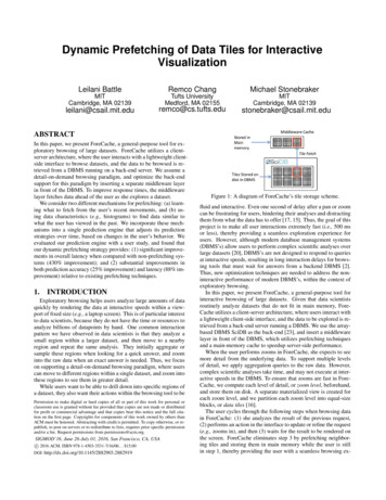
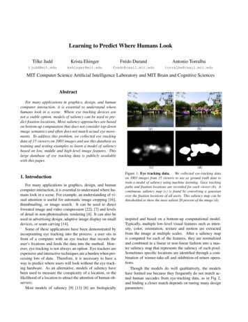
60HornFig. 1. Points in the environment are viewed from two camera positions. The relative orientation is the direction of the baseline b, andthe rotation relating the left and right coordinate systems. The directions of rays to at least five scene points must be known in both cameracoordinate systems.these will be the camera positions and orientations corresponding to the earlier and the later frames respectively.1 The ray from the center of projection of the leftcamera to the center of projection of the right camerais called the baseline (see figure 1). A coordinate systemcan be erected at each projection center, with one axisalong the optical axis, that is, perpendicular to the imageplane. The other two axes are in each case parallel totwo convenient orthogonal directions in the image plane(such as the edges of the image, or lines connectingpairs of fiducial marks).2 The rotation of the left cameracoordinate system with respect to the right is called theorientation.Note that we cannot determine the length of the baseline without knowledge about the length of a line inthe scene, since the ray directions are unchanged if wescale all of the distances in the scene and the baselineby the same positive scale-factor. This means that weshould treat the baseline as a unit vector, and that thereare really only five unknowns—three for the rotationand two for the direction of the baseline.32 Existing Solution MethodVarious empirical procedures have been devised fordetermining the relative orientation in an analog fashion.'In what follows we use the coordinate system of the right (or later)camera as the reference. One can simply interchange left and rightif it happens to be more convenient to use the coordinate system ofthe left (or earlier) camera. The solution obtained in this fashion willbe the exact inverse of the solution obtained the other way. Actually, any coordinate system rigidly attached to the image-formingsystem may be used.'If we treat the baseline as a unit vector, its actual length becomesthe unit of length for all other quantities.Most commonly used are stereoplotters, optical devicesthat permit viewing of image pairs and superimposedsynthetic features called floating marks. Differences inray direction parallel to the baseline are called horizontal disparities (orx-parallaxes), while differences in raydirection orthogonal to the baseline are called verticaldisparities (or y-paraUaxes)4 Horizontal disparities encode distances to points on the surface and are the quantities sought after in measurement of the underlyingtopography. There should be no vertical disparities whenthe device is adjusted to the correct relative orientation,since rays from the left and right projection center mustlie in a plane that contains the baseline (an epipolarplane) if they are to intersect.The methods used in practice to determine the correctrelative orientation depend on successive adjustmentsto eliminate the vertical disparity at each of five or siximage points that are arranged in one or another specially designed pattern [32, 39, 45, 50, 55]. In eachof these adjustments, a single parameter of the relativeorientation is varied in order to remove the vertical disparity at one of the points. Which adjustment is madeto eliminate the vertical disparity at a specific pointdepends on the particular method chosen. In each case,however, one of the adjustments, rather than being guidedvisually, is made by an amount that is calculated, usingthe measured values of earlier adjustments. The calculation is based on the assumptions that the surface beingviewed can be approximated by a plane, that the baseline is roughly parallel to this plane, and that the opticalaxes of the two cameras are roughly perpendicular tothis plane.5The whole process is iterative in nature, since thereduction of vertical disparity at one point by meansof an adjustment of a single parameter of the relativeorientation disturbs the vertical disparity at the otherpoints. Convergence is usually rapid if a good initialguess is available. It can be slow, however, when theassumptions on which the calculation is based are violated, such as in "accidented" or hilly terrain [54].These methods typically use Euler angles to representthree-dimensional rotations [26] (traditionally denotedby the Greek letters K, t , and &)). Euler angles have a*This naming convention stems from the observation that, in the usualviewing arrangement, horizontal disparities correspond to left-rightdisplacements in the image, whereas vertical disparities correspondto up-down displacements.'While these very restrictive assumptions are reasonable in the caseof typical aerial photography, they are generally not reasonable inthe case of terrestrial or industrial photogrammetry, or in robotics.
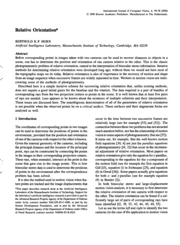
Relative Orientationnumber of shortcomings for describing rotations thatbecome particularly noticeable when these anglesbecome large.6There also exist related digital procedures that converge rapidly when a good initial guess of the relativeorientation is available, as is usually the case when oneis interpreting aerial photography [45]. Not all of thesemethods use Euler angles. Thompson [49], for example,uses twice the Gibb's vector [26] to represent rotations.These procedures may fail to converge to the correctsolution when the initial guess is far off the mark. Inthe application to motion vision, approximate transiational and rotational components of the motion are oftennot known initially, so a procedure that depends ongood initial guesses is not particularly useful. Also, interrestrial, close-range [35] and industrial photogrammetry [8] good initial guesses are typically harder tocome by than they are in aerial photography.Normally, the directions of the rays are obtained frompoints generated by projection onto a planar imagingsurface. In this case the directions are confined to thefield of view as determined by the active area of theimage plane and its distance to the center of projection.The field of view is always less than a hemisphere, sinceonly points in front of the camera can be imaged.7 Themethod described here applies, however, no matter howthe directions to points in the scene are determined.There is no restriction on the possible ray directions.We do assume, however, that we can tell which of twoopposite semi-infinite line segments the point lies on.If a point lies on the correct line segment, we will saythat it lies in front of the camera, otherwise it will beconsidered to be behind the camera (even when theseterms do not strictly apply).The problem of relative orientation is generally considered solved, and so has received little attention inthe photogrammetric literature in recent times [54]. Inthe annual index of Photogrammetric Engineering, forexample, there is only one reference to the subject inthe last ten years [10] and six in the decade before that.This is very little in comparison to the large numberof papers on this subject in the fifties, as well as thesixties, including those by Gill [13], Sailor [39],Jochmann [25], Ghosh [U], Forrest [7], and Oswal [36].'The angles tend to be small in traditional applications to photographstaken from the air, but often are quite large in the case of terrestrialphotogrammetry.The field of view is, however, larger than a hemisphere in somefish-eye lenses, where there is significant radial distortion.61In this paper we discuss the relationship of relativeorientation to the problem of motion vision in the situation where the motion between the exposure of successive frames is relatively large. Also, a new iterativealgorithm is described, as well as a way of dealing withthe situation when there is no initial guess available forthe rotation or the direction of the baseline. The advantages of the unit quaternion notation for representingrotations are illustrated as well. Finally, we discuss critical surfaces, surface shapes that lead to difficulties inestablishing a unique relative orientation.(One of the reviewers pointed out that L. Hinsken[16, 17] recently obtained a method for computing therelative orientation based on a parameterization of therotation matrix that is similar to the unit quaternion representation used here. In his work, the unknown parameters are the rotations of the left and right cameras withrespect to a coordinate system fixed to the baseline,while here the unknowns are the direction of the baseline and the rotation of a coordinate system fixed to oneof the cameras in a coordinate system fixed to the othercamera. Hinsken also addresses the simultaneous orientation of more than two bundles of rays, but says littleabout multiple solutions, critical surfaces, and methodsfor searching the space of unknown parameters.)3 Coplanarity ConditionIf the ray from the left camera and the correspondingray from the right camera are to intersect, they mustlie in a plane that also contains the baseline. Thus, ifb is the vector representing the baseline, r,. is the rayfrom the right projection center to the point in the sceneand r; is the ray from the left projection center to thepoint in the scene, then the triple product[b r; r,](1)equals zero, where r/ rot(r;) is the left ray rotatedinto the right camera's coordinate system.8 This is thecoplanarity condition (see figure 2).We obtain one such constraint from each pair of rays.There will be an infinite number of solutions for thebaseline and the rotation when there are fewer than fivepairs of rays, since there are five unknowns and eachpair of rays yields only one constraint. Conversely, if The baseline vector b is here also assumed to be measured in thecoordinate system of the right camera.
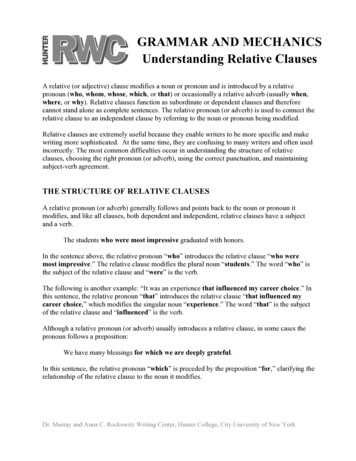
62Horndeparture from best fit. It is worthwhile exploring thegeometry of the two rays more carefully to see this.Consider the points on the rays where they approacheach other the closest (see figure 2). The line connecting these points will be perpendicular to both rays, andhence parallel to (r/ x r,.). As a consequence, we canwritear;' 7(r/ x r,.) b i8r,Fig. 2. Two rays approach closest where they are intersected by aline perpendicular to both. If there is no measurement error, andthe relative orientation has been recovered correctly, then the tworays actually intersect. In this case the two rays and the baseline ina common plane.there are more than five pairs of rays, the constraintsare likely to be inconsistent as the result of small errorsin the measurements. In this case, no exact solution ofthe set of constraint equations will exist, and it makessense instead to minimize the sum of squares of errorsin the constraint equations. In practice, one should usemore than five pairs of rays in order to reduce the influence of measurement errors [25]. We shall see laterthat the added information also allows one to eliminatespurious apparent solutions.In the above we have singled out one of the twoimage-forming systems to provide the reference coordinate system. It should be emphasized that we obtainthe exact inverse of the solution if we chose to use acoordinate system aligned with the other image-formingsystem instead.4 What Is the Appropriate Error Term?In this section we discuss the weights w by which thesquares of the triple products [b r/r,.] should be multiplied in the total sum of errors. The reader may wishto skip this section upon first reading, but keep in mindthat there is some rational basis for choosing theseweights. Also note that one can typically compute agood approximation to the exact least-squares solutionwithout introducing the weighting factors.The triple product t [b r/r,.] is zero when the leftand right ray are coplanar with the baseline. The tripleproduct itself is, however, not the ideal measure of(2)where a and j8 are proportional to the distances alongthe left and the right ray to the points where they approach most closely, while 7 is proportional to theshortest distance between the rays. We can find 7 bytaking the dot-product of the equality above with r/ xr,. We obtain7 l r;xtV 2 [b r; r,](3)Similarly, taking dot-products with r,. X (r/ X r,.) andr;' x (r/ X r,.), we obtaina r; x r, p (b X r,) (r; X r,)13 r; x r, 2 (b x r;) (r; x r,)(4)Clearly, a r;' and r,. are the distances along therays to the points of closest approach.9Later we will be more concerned with the signs ofa and f S . Normally, the points where the two rays approach the closest will be in front of both cameras, thatis, both a and 13 will be positive. If the estimated baseline or rotation is in error, however, then it is possiblefor one or both of the calculated parameters a and f3to come out negative. We will use this observation laterto distinguish among different apparent solutions. Wewill call a solution where all distances are positive apositive solution. In photogrammetry one is typicallyonly interested in positive solutions.The perpendicular distance between the left and theright ray isd 7 r, x r,[b r; r,]l r; x r, (5)This distance itself, however, is also not the ideal measure of departure from best fit, since the measurementerrors are in the image, not in the scene (see also thediscussion in [9]. A least-squares procedure should bebased on the error in determining the direction of therays, not on the distance of closest approach. We need'The dot-products of the cross-products can, of course, be expandedout in terms of differences of products of dot-products.
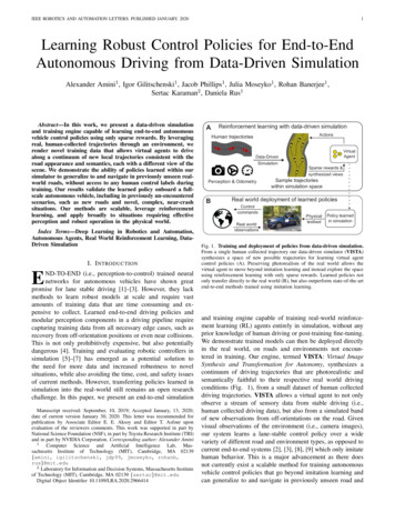
Relative Orientation63to relate variations in ray direction to variations in theperpendicular distance between the rays, and hence thetriple product.Suppose that there is a change 60; in the vertical disparity of the left ray direction and b6r in the verticaldisparity of the right ray direction. That is, r/ and r,.are changed by adding6r,; 6r,r; X r,llr; X r, r/ x r,l r; (6) M60,llr/ x r, respectively. Then, from figure 3, we see that thechange in the perpendicular distance d is just 60; timesthe distance form the left center of projection to thepoint of closest approach on the left ray, minus 60,.times the distance from the right center of projectionto the point of closest approach on the right ray, or6d a\\r;\\66i - IS\\r,\\66,(7)From equation (5) we see that the corresponding changein the triple product is6r r;x r,\\6dThus if the variance in the determination of the verticaldisparity of the left ray is a], and the variance in thedetermination of the vertical disparity of the right rayis (T? , then the variance in the triple product will be10k x rj 2 (8)o? r; x r, p (a2 r; 2 a] fS 2 r, 2 a?)(9)r2 orThis implies that we should apply a weightw a /af(10)to the square of each triple product in the sum to beminimized, where cr2 is arbitrary (see Mikhail andAckerman [31], p. 65). Written out in full we have'"The error in determining the direction of a ray depends on imageposition, since a fixed interval in the image corresponds to a largerangular interval in the middle of the image than it does at the periphery. The reason is that the middle of the image is closer to the centerof projection than is the periphery. In any case, one can determinewhat the variance of the error in vertical disparity is, given the imageposition and the estimated error in determining positions in the image.Fig. 3. Variations in the triple product t [b r; r,.] can be relatedto variations in the perpendicular distance d between the two rays.Variations in this distance, in turn, can be related to variations inthe measurement of the directions of the left and right rays. Theserelationships can be used to arrive at weighting factors that allowminimization of errors in image positions while working with thesums of squares of triple products.w r; X ivlpag- [((b x r,) (r; x r,))2z/r? ((b x ( r / x r,))2 r, pa?](11)(Note again that errors in the horizontal disparity donot influence the computed relative orientation; insteadthey influence errors in the distances recovered usingthe relative orientation).Introduction of the weighting factors makes the sumto be minimized quite complicated, since changes inbaseline and rotation affect both numerators and denominators of the terms in the total error sum. Near thecorrect solution, the triple products will be small andso changes in the estimated rotation and baseline willtend to induce changes in the triple products that arerelatively large compared to the magnitudes of the tripleproducts themselves. The changes in the weights, onthe other hand, will generally be small compared tothe weights themselves. This suggests that one shouldbe able to treat the weights as constant during a particular iterative step.Also note that one can compute a good approximationto the solution without introducing the weighting factorsat all. This approximation can then be used to start aniterative procedure that does take the weights into account, but treats them as constant during each iterativestep. This works well because changes in the weightsbecome relatively small as the solution is approached.
64Horn5 Least Squares Solution for the BaselineCb XbIf the rotation is known, it is easy to find the best-fitbaseline, as we show next. This is useful, despite thefact that we do not usually know the rotation. The reasonis that the ability to find the best baseline, given a rotation, reduces the dimensionality of the search spacefrom five to three. This makes it much easier to systematically explore the space of possible starting values forthe iterative algorithm.Let {r/,} and {r ,}, for ; 1, . . . . n, be corresponding bundles of left and right rays. We wish tominimizennE S w,[b r;,, r,,,]2 w (r;',. x ' r,,))2 (12)subject to the condition b b 1, where r/; is therotated left ray r;; as before. If we let c, r/, X r ,,we can rewrite the sum in the simpler formr"i S w,(b c,)2 b7' w;c,c,7' b(13); 1where we have used the equivalence b c, b ;,which depends on the interpretation of column vectorsas 3x1 matrixes. The term c cf is a dyadic product,a 3x3 matrix obtained by multiplying a 3x1 matrixby a 1x3 matrix.The error sum is a quadratic form involving the realsymmetric matrix."7C S w;c,c, 'i i(14)The minimum of such a quadratic form is the smallesteigenvalue of the matrix C, attained when b is the corresponding unit eigenvector (see, for example, the discussion of Rayleigh's quotient in Korn and Korn [26].This can be verified by introducing a Lagrangianmultiplier X and minimizingE' b b X(l - b b)(15)subject to the condition b 1. Differentiating withrespect to b and setting the result equal to zero yields"The terms in the sum of dyadic products forming the matrix C contain the weights discussed in the previous section. This only makessense, however, if a guess is already available for the baseline—unitweights may be used otherwise.(16)The error corresponding to a particular solution of thisequation is found by premultiplying by b7:E b b Xb'b X(17)The three eigenvalues of the real symmetric matrix Care non-negative, and can be found in closed form bysolving a cubic equation, while each of the corresponding eigenvectors has components that are the solutionof three homogeneous equations in three unknowns [26].If the data are relatively free of measurement error, thenthe smallest eigenvalue will be much smaller than theother two, and a reasonable approximation to the soughtafter result can be obtained by solving for the eigenvector using the assumption that the smallest eigenvalueis actually zero. This way one need not even solve thecubic equation (see also Horn and Weldon [24]).If b is a unit eigenvector, so is -b. Changing thesense of the baseline does not change the magnitudeof the error term [b r/r,.]. It does, however, changethe signs of a, 13, and 7. One can decide which senseof the baseline direction is appropriate by determiningthe signs of a, and j8, for ;' 1, . . . , n. Ideally, theyshould all be positive, but when the baseline and therotation are incorrect they may not be.The solution for the optimal baseline is not uniqueunless there are at least two pairs of corresponding rays.The reason is that the eigenvector we are looking foris not uniquely determined if more than one of theeigenvalues is zero, and the matrix has rank less thantwo if it is the sum of fewer than two dyadic productsof independent vectors. This is not a significant restriction, however, since we need at least five pairs of raysto solve for the rotation anyway.6 Iterative Improvement of Relative OrientationIf one ignores the orthonormality of the rotation matrix,a set of nine homogeneous linear equations can be obtained by a transformation of the coplanarity conditionsthat was first described by Thompson [49]. These equations can be solved when eight pairs of correspondingray directions are known [38, 27]. This is not a leastsquares method that can make use of redundant measurements, nor can it be applied when fewer than eightpoints are given. Also, the method is strongly affectedby measurement errors and fails for certain configurations of points [28].
Relative OrientationNo true closed-form solution of the least-squares problem has been found for the general case, where bothbaseline and rotation are unknown. However, it is possible to determine how the overall error is affected bysmall changes in the baseline and small changes in therotation. This allows one to make iterative adjustmentsto the baseline and the rotation that reduce the sum ofsquares of errors.We can represent a small change in the baseline byan infinitesimal quantity 6b. If this change is to leavethe length of the baseline unaltered, then b 6b 2 b p(18) b 2 2b 6b 6b 2 b 2(19)orIf we ignore quantities of second-order, we obtain6b b 0t [b r; r,], c r/ x r,, d r; x (r, x b) (26)Now, we are trying to minimizen S w. c; 6b d. 6W)2i i(20)This follows from Rodrigues' formula for the rotationof a vector rcos 6 r sin 6 (.w X r) (1 - cos 0)(o) r)o) (21)if we let 0 6u , u 6u/ 6w , and note that 6uis an infinitesimal quantity. Finally then, we see thatt [b r/ r,.] becomest 6t [(b 6b) (r;' 6w x r/) ly] (22)subject to the condition b 6b 0. We can introducea Lagrange multiplier in order to deal with the constraint. Instead of minimizing E itself, we then haveto minimizeE' E 2X(b 6b)n w;(r, c, 6b d; 6(tf)c, Xb 0(29)By taking the dot-product of this expression with b, andusing the fact that b b 1 one can see thatX - w,(t, c, 6b d, 6w)t,if we ignore the term [6b (6w X r/) r,.], because itcontains the product of two infinitesimal quantities. Wecan expand two of the triple products in the expressionabove and obtain(30)i lwhich means that -X is equal to the total error whenone is at a stationary point, where 6b and 6w are equalto zero.If we differentiate E' with respect to 6w and set thisresult also equal to zero, we obtain w,(t, c, 6b d, 6t»)d, 0(12)Finally, if we differentiate " with respect to X we getback the constraintb 6b 0[b r;r,] [6b r;r,] [b (60, X r;) r,] (23)(32)The two vector equations and the one scalar equation(equations (29), (31), and (32)) constitute seven linearscalar equations in the six unknown components of6band 6(d and the unknown Lagrangian multiplier X. Wecan rewrite them in the more compact form:[b r; r,] (r; x r,) 6b (r, x b) (60) x r;) (24)C 6b F 60 Xb -corF7 6b D 6&? -dfor short, where(28)(where the factor of two is introduced to simplify thealgebra later). Differentiating E' with respect to 6b, andsetting the result equal to zero yieldsor,t c 6b d 6o»(27)i lthat is, 6b must be perpendicular to b.A small change in the rotation can be representedby an infinitesimal rotation vector 6w. The direction ofthis vector is parallel to the axis of rotation, while itsmagnitude is the angle of rotation. This incrementalrotation takes the rotated left ray, r/, intor;" r;' (6&? x r,')65b7' 6b 0(25)or(33)
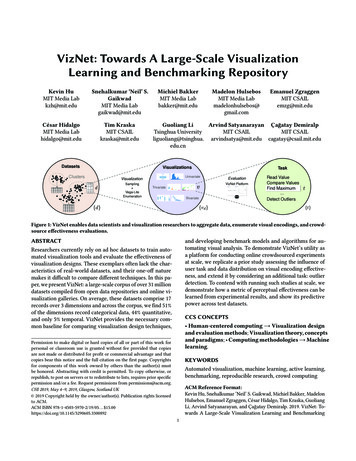
66HornCFb6b'F' D 0oo777b ' O " 0- r - \C(34)\- X /wherec sw;c,c7'F 1; w.c.d71 1(35)nZ) Sw,d, whilec S w,t,c, and d w,r,d,; ii i(36)The above gives us a way of finding small changes inthe baseline and rotation that reduce the overall errorsum.12 The equations shown (equation (34)) are thesymmetric normal equations (see also Mikhail andAckerman [31], p. 229) and yield incremental adjustments for the rotation and the baseline.13 This methodcan be applied iteratively to locate a minimum. Numerical experiments confirm that it converges rapidly whena good initial guess is available.7 Singularities and Sensitivity to ErrorsThe computation of the incremental adjustments cannotbe carried out with precision when the coefficientmatrix becomes ill conditioned. This occurs when thereare fewer than five pairs of rays, as well as for certain"It is also possible to reduce the problem to the solution of six linearequations in six unknowns by first eliminating the Lagrangian multiplier \ using b b 1 [22], but this leads to an asymmetrical coefficient matrix that requires more work to set up. One of the reviewerspointed out that the symmetric normal equations can be solveddirectly, as shown above."Note that the customary savings of about half the computation whensolving a system of equations with symmetric coefficient matrix cannotbe fully achieved here since the last element on the main diagonalis zero. It may also be of interest to note that the top left 6x6 submatrix has at most rank n, since it is the sum o f n dyadic products—itthus happens to be singular when n 5.rare configurations of points in the scene (see the discussion of critical surfaces later). The coefficient mat
the relative orientation of one camera with respect to the other. The relative orientation can be found if a suf-ficiently large set of pairs of corresponding rays have been identified [12, 19, 32, 43, 44, 45, 49, 55]. Let us use the terms left and right to identify the two cameras (in the case of the application to motion vision