Transcription
Automatic Bottle Filling System Using PLCA project report submitted in partial fulfillmentOf the requirement for the degree of B. Tech in Electrical EngineeringByPrithwish Das(11701614033)Krishnendu Mandal (11701614023)Paromita Das(11701614031)Under the supervision ofProf. (Dr.) Alok Kole, HoD, Electrical EngineeringDepartment of Electrical EngineeringRCC INSTITUTE OF INFORMATION TECHNOLOGYCANAL SOUTH ROAD, BELIAGHATA, KOLKATA – 700015, WEST BENGALMaulana Abul Kalam Azad University of Technology (MAKAUT) 2018Page 1
AcknowledgementIt is my great fortune that I have got opportunity to carry out this project work under thesupervision of Prof. (Dr.) Alok Kole in the Department of Electrical Engineering, RCC Instituteof Information Technology (RCCIIT), Canal South Road, Beliaghata, Kolkata-700015, affiliatedto Maulana Abul Kalam Azad University of Technology (MAKAUT), West Bengal, India. Iexpress my sincere thanks and deepest sense of gratitude to my guide for his constant support,unparalleled guidance and limitless encouragement.I wish to convey my gratitude to Prof. (Dr.) Alok Kole, HOD, Department of ElectricalEngineering, RCCIIT and to the authority of RCCIIT for providing all kinds of infrastructuralfacility towards the research work.I would also like to convey my gratitude to all the faculty members and staffs of theDepartment of Electrical Engineering, RCCIIT for their whole hearted cooperation to make thiswork turn into e and Signature of the StudentPlace:Date:Page 2
CERTIFICATETo whom it may concernThis is to certify that the project work entitledAutomatic Bottle Filling SystemUsing PLC is the bona fide work carried out by Prithwish Das (11701614033),Krishnendu Mandal (11701614023) and Paromita Das (11701614031), a studentof B.Tech in the Dept. of Electrical Engineering, RCC Institute of InformationTechnology (RCCIIT), Canal South Road, Beliaghata, Kolkata-700015, affiliated toMaulana Abul Kalam Azad University of Technology (MAKAUT), West Bengal, India,during the academic year 2017-18, in partial fulfillment of the requirements for thedegree of Bachelor of Technology in Electrical Engineering and that this project hasnot submitted previously for the award of any other degree, diploma and fellowship.Signature of the GuideSignature of the HODName:Name:DesignationDesignationSignature of the External ExaminerName:Designation:Page 3
AbstractThe objective of our project is to design, develop and monitor “Automatic bottle filling systemusing PLC”. This work provides with a lot of benefits like low power consumption, lowoperational cost, less maintenance, accuracy and many more. This project is based on Industrialautomation and is a vast application used in many industries like milk industries, chemical, food,mineral water and many industrial manufacturers. A prototype has been developed to illustratethe project.Filling is the task that is carried out by a machine and this process is widely used in manyindustries. In this project, the filling of the bottle is controlled by using a controller known asPLC which is also the heart of the entire system. For the conveyor system, a dc motor has beenselected for better performance and ease of operation. A sensor has been used to detect theposition of the bottle. In our project we have used less number of system hence the overall costhas been reduced to an extent. Ladder logic has been used for the programming of the PLC,which is the most widely used and accepted language for the programming of the PLC. The PLCused in this system is a Siemens S7 – 1200 which makes the system more flexible and easy tooperate.Page 4
Table of Contents1. INTRODUCTION1.1 Overview1.2 Literature Review2. ABOUT PLC2.1 Technical specification of PLC2.2 PLC concepts2.3 Programming concepts3. FEASIBILITY STUDY3.1 Understanding feasibility3.2 Economical feasibility3.3 Technical feasibility3.4 Behavioural feasibility4. SOFTWARE IMPLEMENTATION4.1 Flowchart4.2 Algorithm4.3 Ladder Logic Diagram (LAD)5. HARDWARE REQUIREMENT SPECIFICATION5.1 Water Float Switch5.2 Photoelectric Sensor5.3 DC geared motor5.4 Water pump5.5 SMPS5.6 Solenoid Valve5.7 Water tank5.8 Switches5.9 Relays5.10 Conveyor System6. SYSTEM DESIGN6.1 Block Diagram6.2 Schematic Diagram6.3 MethodologyPage 5
6.4 Connection diagram6.5 Our prototype design7. RESULT AND DISCUSSION8. CONCLUSION AND FURTHER SCOPE FOR DEVELOPMENTREFERENCESPage 6
CHAPTER 1INTRODUCTIONPage 7
OverviewThe project is based on industrial automation and PLC is the heart of automation. The hardwareand the software are the two important areas in our project.1) HARDWARE DESCRIPTION:In this project, Siemens PLC SIMATICS S7 1200 is used for controlling the inputs andoutputs. Input supply to the PLC is given through a SMPS. The rating of the SMPS is24V DC 5Amps. The PLC used here is a compact PLC which has fixed number of inputsand outputs. In this kind of PLC model, the CPU contains 14 digital inputs and 10 digitaloutputs. One diffused photoelectric sensor has been used for the positioning of thebottles. A geared DC motor has been used for running the conveyor system. The ratingsof the DC motor is 12V and 50 RPM speed with a high starting torque of 70 Kg-cm (atno load). Toggle switches are used to serve the purpose of some inputs to the PLC.2) SOFTWARE DESCRIPTION:There are five important languages which are used for the programming of the PLC. Thelist of the methods are as follows: Functional block diagram (FBD) Structure text Instruction list Flow chart Ladder diagramOut of these five languages, ladder diagram is the most widely used language and issimple as compared to other languages. Ladder diagram has been used for theprogramming of this PLC.Page 8
Literature ReviewA brief survey of technologies explored during the past decade and some of them is given belowto provide an understanding of the level of research interest in this domain. In this paper,researcher outlined the various phases of operation involved in the adaptation of a manuallyoperated boiler towards a totally automated boiler. The first part of the paper focuses on passingthe inputs to the boiler at a required temperature, so as to constantly maintain a particulartemperature in the boiler. The Air pre heater and Economizer helped in this method. And thepaper mainly focused on level, pressure and flow control at the various stages of the boiler plant.Thus the temperature in the boiler is constantly monitored and brought to a constant temperatureas required by the power plant. The automation is further improved by constant monitoring usingSCADA screen which is connected to the PLC by means of communication cable. By means oftag values set to various parameters in SCADA the entire process is controlled. At the automatedpower plant, the boiler is controlled by Variable Frequency Drive (VFD) to put in action therequired processes to be carried out at the boiler. Thus the entire cycle is carried out as a paperand at various stages each phase is detailed out. This paper has proved to be very efficientpractically as the need for automation grows day by day.This paper presented a SCADA system for a plant whose product demand is varying accordingto the temperature. This paper also gives an automatic method of changing a production fromone mode to another. There is no manual shifting required. This paper gives a way to get rid offexcess production. It also provides the facility to the user to over ride the any one of the unithardware operation from the control room.Researchers developed a design of re-usability using modular modeling techniques. Reimplementation of program of existing PLC program based on formulization and visualization. Itis done by transformation of FSM in XML format into IEC 61131-3 POUs and project is to becreating to control machine using new controller.Prior to the development of data acquisition and control system, collecting data from remotefield instruments, distributed throughout the plant in huge manufacturing industries, was a quitechallenging and multifaceted task. The team of researcher has been developed an industrial dataacquisition and control systems equipped these industries with facilities to gather and processdata, and perform control actions right from a centralized location, i.e. control room, withoutactually going to the plant. They introduction of programmable logic controllers (PLC) as a dataacquisition and control hardware in these systems increased its reliability and robustness. Thispaper highlights the design work carried out to develop a cost efficient, simple, robust andintelligent industrial standard data acquisition and control system for two physical field plantsthat are 50 meters apart from the control room. This work highlights process control applicationand indeed is an application of industrial electronics engineering. The work carried out for thisPage 9
data acquisition and control system is in correlation with SCADA, DCS and totally integratedautomation, which is meant to optimize processes and manufacturing procedures at the sametime. At present, the PLC has been widely used in the industry area. But the shortcoming of thiscontroller appears along with the growth of the industry equipments. Such as inferiorcompatibility cooperate with the new equipments, poor satisfaction of the high calculation andweak communication and so on. Thus, there need new technology to satisfy the increasingindustry demands. The soft PLC comes into the world from on kind of condition. The function ofPLC is imitated through software on the PC platform. But the soft PLC has shortage also. Thesturdiness and instantaneity is worse than the traditional PLC. Therefore, the embedded PLCcombines the advantages of traditional PLC and soft PLC, increase the computing power,express the advantages of ladder diagram and open construction to bring a universal platform tothe controlled members.In this research paper, the group of authors took efforts on the improvement of demonstratinghow industrial temperature automation can be achieves using modest hardware and more refinedsoftware details. The prime concern was to generate firing pulse for an HVAC controllingactuator while displacing them at the same time to vary the magnitude of the ac voltage output.The direction of displacement of the pulse was described by the SETPOINT definition from anHMI using AT commands, and FEEDBACK from the temperature sensor installed in theindustrial background. The mathematical modeling was done in LabVIEW for investigating theeffect of varying firing angle on the magnitude of the ac voltage. This controlled variation ofoutput ac voltage can be subjected to controlling temperature of the particular industrialenvironment.With the help of PLC, researcher has been build and implements logic for Industrial CraneAutomation & Monitoring. The soft wiring advantage provided by programmable controllers isTremendous. In fact, it is one of the most important features of PLCs. Soft wiring makes changesin the control system easy and cheap. If it want a device in a PLC system to behave differently orto control a different process element, all have to do is change the control Program. In atraditional system, making this type of change would involve physically changing the wiringbetween the devices, a costly and time-consuming attempt. In future definitely PLC is dominatedon all other controlling methods.The team of authors developed ladder logic in MICROLOGIX software and is verified in AllenBradley PLC. A ladder logic program of a typical application often results in complex softwarethat is difficult to manage during configuration, and especially, during maintenance. Thedifficulty lies in a typical problem with real-time control software that is exacerbated by ladderlogic. Individual components of PLC software are characteristically asynchronous, resulting inunpredictable interactions. This makes the initial configuration of the software (i.e.,commissioning) extremely difficult and labour-intensive, but also makes reconfiguration risky.However the system creates a fast, real-time decision making environment. Also the use ofSCADA in the industry will not only allow them to minimize the cost associated with the displayPage 10
and recording instruments but will also account for better quality and higher productivity. Theprocess is adaptable to any changes in production capacity or safety requirements. In shortintegrated automation process produces a reliable quality hardboard production industry with thehelp of PLC. This paper focuses on an innovative and intelligent monitoring system of processusing SCADA. The main concept of paper is data acquisition & controlling by using SCADAsoftware with the help of PLC. Here PLC is a medium between electrical system & PersonalComputer for SCADA to take input and output bits. Automating electrical distributions systemsby implementing a supervisory control and data acquisition (SCADA) system is the one of themost cost-effective solutions for improving reliability, increasing utilization, increasingefficiency and saving costs.This paper presented an automatic control of temperature and level of Continues Stirred TankReactor (CSTR) using PLC and SCADA. The CSTR is heated using heating-coil and itstemperature and level are measured by RTD and float type level sensor respectively. Theaccurate control of temperature and level are the realistic feature of this system and balances theprocess. Automation required gaining the complete control of manufacturing process to achieveconsistency in manufacturing with increased productivity by shortening manufacturing time. Inthis paper we consider both Batch and Continues process control using PLC and SCADA. ThePLC and SCADA control the process parameters with good accuracy and results are found to besatisfactorily. This is a simple automated process and can be applied in many mixing processesused in industries. In this research paper, the device temperature parameter of different zones offurnace has been constantly monitored and hence it can be further controlled by using DAQ andcontrol system. The constant monitoring of such different furnace zone temperature can producedata-base for scheduling of the machine servicing, troubleshooting and also for futureprocessing. Due to use of microcontroller the computation task has been handled mosteffectively. Hence group of authors proposed system has been widely used in automotiveengineering, instrumentation and power quality monitoring and control applications. Dataacquisition system for monitoring such temperature of brazing furnace provides advantages ofdesign simplicity, portability and less cost.This paper reveals the design of LabVIEW based SCADA system for centralized control. Itmakes use of PLC as a field controller to operate the prototype design of Stenter Machine,widely used in textile industries. LabVIEW, which is a commonly accepted graphical userinterface environment, also provides HMI front end. The PLC controller and the LabVIEWbased SCADA are communicating through the RS-232 link. The control system is flexible andmodular. Due to the intuitive programming of LabVIEW, this system is cost efficient andreliable solution for automation of small scale textile industries.The system introduced by a group of researchers is an experimental study which helps incontrolling the characteristics and ON/OFF states of a control valve. A graphical user Interfacehas been developed using supervisory control and data acquisition (SCADA) and theprogramming of the control system has been done using programmable logic control (PLC). APage 11
descriptive study has been incorporated in this paper to formulize all factors responsible for thechange in valve characteristics. This system gives a clear idea about the opening and closing ofthree types of valves which may be present as per its requirement in an industry. The user of thesystem is able to supply input parameters so as to efficiently control the valve. The system ishighly efficient and cost effective, as only one interfaced digital system along with a PLC cancontrol many subsequent valves.Page 12
Chapter 2ABOUT PLCPage 13
Technical Specification of PLCThe CPU combines a microprocessor, an integrated power supply, input and output circuits,built-in PROFINET, high speed motion control I/O and on board analog inputs in a compacthousing to create a powerful controller. After downloading a program, the CPU contains thelogic required to monitor and control the devices in the application. The CPU monitors theimputs and changes the output according to the logic of the user's program.The CPU provides a PROFINET port for communication over a PROFINET network.Power BudgetThe CPU has an internal power supply that provides power for the CPU, the signal modules,signal board and communication modules and for other 24VDC user power requirements.5VDC logic budget supplied by the CPU and the 5VDC power requirements of the signalmodules, signal boards and communication modules.The CPU provides a 24 VDC sensor supply that can supply 24 VDC for input points, for relaycoil power on the signal modules, or for other requirements. If your 24 VDC power requirementsexceed the budget of the sensor supply, then you must add an external 24 VDC power supply toyour system.Some of the 24 VDC power input ports in the S7-1200 system are interconnected, with acommon logic circuit connecting multiple M terminals. For example, the following circuits areinterconnected when designated as "not isolated" in the data sheets: the 24 VDC power supply ofthe CPU, the power input for the relay coil of an SM, or the power supply for a nonisolatedanalog input. All non-isolated M terminals must connect to the same external reference potential.Page 14
General Specification of CPU 1214CCPU features:Technical DataUser memory – Work Load RetentiveOn – board digital I/OOn – board analog I/OProcess image sizeBit Memory (M)Temporary (local) memorySignal modules expansionSB, CB, BB expansionCommunication module expansionHigh – speed countersPulse outputsPulse catch inputsTime delay/cyclic interruptsEdge interruptsMemory cardReal time clock accuracyReal time clock retention timeDescription 75 Kbytes4 Mbytes internal, expandable uptoSD card size10 Kbytes14 inputs/ 10 outputs2 inputs1024 bytes of inputs (I)/ 1024 bytes ofoutputs (Q)8192 bytes 16 kbytes for startup and programcycles (including associated FBs andFCs) 4 kbytes for standard interrupt eventsincluding FBs and FCs 4 kbytes for error interrupt eventsincluding FBs and FCs8 SMs max.1 max3 CMs max6 total Single phase: 3 at 100kHz and 3 at30kHz clock rate Quadrature phase: 3 at 80kHz and 3at 20kHz clock rate4144 total with 1ms resolution12 rising and 12 falling (14 and 14 withoptional signal board)SIMATIC Memory card (optional) /- 60 seconds/month20 days typ./12 days min. at 40 oC(maintenance free super capacitor)Power Supply:Technical DataPage 15
Voltage rangeLine frequencyInput current (max. load)Ground leakage, AC line to functionalearthHold up time (loss of power)85 to 264 VAC47 to 63 Hz CPU only – 100 mA at 120VAC;50mA at 240 VAC CPU with all expansion accessories –300mA at 120 VAC; 150mA at 240VAC0.5 mA max.20ms at 120 VAC; 80ms at 240 VACDigital Inputs and Outputs: Number of inputs: 14 Rated voltage: 24 VDC at 4 mA, nominal Surge voltage: 35 VDC for 0.5 sec Logic 1 signal (min.): 15 VDC at 2.5 mA Logic 0 signal (max.): 5 VDC at 1 mA Number of outputs: 10 Current (max.): 2A Surge current: 7A with contacts closed Maximum relay switching frequency: 1 HzPage 16
PLC ConceptsExecution of the user programThe CPU supports the following types of code blocks that allow us to create an efficientstructure for our user program: Organization blocks (OBs) define the structure of the program. Some OBs havepredefined behavior and start events, but we can also create OBs with custom startevents.Functions (FCs) and function blocks (FBs) contain the program code that correspondsto specific tasks or combinations of parameters. Each FC or FB provides a set of inputand output parameters for sharing data with the calling block. An FB also uses anassociated data block (called an instance DB) to maintain state of values betweenexecution that can be used by other blocks in the program. Valid FC and FB numbersrange from 1 to 65535.Data blocks (DBs) store data that can be used by the program blocks. Valid DB numbersrange from 1 to 65535.Execution of the user program begins with one or more optional start-up organization blocks(OBs) which are executed once upon entering RUN mode, followed by one or more programcycle OBs which are executed cyclically.Operating Modes of the CPUThe CPU has three modes of operation: STOP mode, STARTUP mode, and RUN mode.Status LEDs on the front of the CPU indicate the current mode of operation. In STOP mode, the CPU is not executing the program. We can download a project.In STARTUP mode, the startup OBs (if present) are executed once. Interrupt events arenot processed during the startup mode.In RUN mode, the program cycle OBs are executed repeatedly. Interrupt events canoccur and be processed at any point within the RUN mode.PLC data typeThe PLC data type editor lets us define data structures that we can use multiple times in ourprogram. We create a PLC data type by opening the “PLC data types” branch of the project treeand double – clicking the "Add new data type" item. On the newly created PLC data type item,we use two single-clicks to rename the default name and double-click to open the PLC data typeeditor.We create a custom PLC data type structure using the same editing methods that are used in thedata block editor. We then add new rows for any data types that are necessary to create the datastructure that we want.Page 17
If a new PLC data type is created, then the new PLC type name will appear in the data typeselector drop drop-lists in the DB editor and code block interface editor.Potential uses of PLC data types: PLC data types can be used directly as a data type in a code block interface or in datablocks. PLC data types can be used as a template for the creation of multiple global data blocksthat use the same data structure.Page 18
Programming ConceptsStructuring the user programWhen we create a user program for the automation tasks, we insert the instructions for theprogram into code blocks: An organization block (OB) responds to a specific event in the CPU and can interruptthe execution of the user program. The default for the cyclic execution of the userprogram (OB 1) provides the base structure for your user program and is the only codeblock required for a user program. If we include other OBs in our program, these OBsinterrupt the execution of OB 1. The other OBs perform specific functions, such as forstartup tasks, for handling interrupts and errors, or for executing specific program code atspecific time intervals.A function block (FB) is a subroutine that is executed when called from another codeblock (OB, FB, or FC). The calling block passes parameters to the FB and also identifiesa specific data block (DB) that stores the data for the specific call or instance of that FB.Changing the instance DB allows a generic FB to control the operation of a set ofdevices. For example, one FB can control several pumps or valves, with differentinstance DBs containing the specific operational parameters for each pump or valve.A function (FC) is a subroutine that is executed when called from another code block(OB, FB, or FC). The FC does not have an associated instance DB. The calling blockpasses parameters to the FC. The output values from the FC must be written to a memoryaddress or to a global DB.Programming LanguageSTEP 7 provides the following standard programming languages for S7-1200: LAD (ladder logic) is a graphical programming language. The representation is based oncircuit diagrams. FBD (Function Block Diagram) is a programming language that is based on the graphicallogic symbols used in Boolean algebra. SCL (structured control language) is a text-based, high-level programming language.Ladder Logic (LAD)The elements of a circuit diagram, such as normally closed and normally open contacts, andcoils are linked to form networks.Page 19
To create the logic for complex operations, you can insert branches to create the logic for parallelcircuits. Parallel branches are opened downwards or are connected directly to the power rail. Youterminate the branches upwards.LAD provides "box" instructions for a variety of functions, such as math, timer, counter, andmove.STEP 7 does not limit the number of instructions (rows and columns) in a LAD network.Function Block DiagramLike LAD, FBD is also a graphical programming language. The representation of the logic isbased on the graphical logic symbols used in Boolean algebra.Mathematical functions and other complex functions can be represented directly in conjunctionwith the logic boxes.STEP 7 does not limit the number of instructions (rows and columns) in an FBD network.SCLStructured Control Language (SCL) is a high-level, PASCAL-based programming language forthe SIMATIC S7 CPUs. SCL supports the block structure of STEP 7.SCL instructions use standard programming operators, such as for assignment (: ), mathematicalfunctions ( for addition, - for subtraction, * for multiplication, and / for division). SCL also usesstandard PASCAL program control operations, such as IF-THEN-ELSE, CASE, REPEATUNTIL, GOTO and RETURN. We can use any PASCAL reference for syntactical elements ofthe SCL programming language. Many of the other instructions for SCL, such as timers andcounters, match the LAD and FBD instructions.We can designate any type of block (OB, FB, or FC) to use the SCL programming languageat the time we create the block. STEP 7 provides an SCL program editor that includes thefollowing elements: Interface section for defining the parameters of the code block Code section for the program code Instruction tree that contains the SCL instructions supported by the CPUPage 20
We enter the SCL code for our instruction directly in the code section. For more complexinstructions, we simply drag the SCL instructions from the instruction tree and drop them intoour program. We can also use any text editor to create an SCL program and then importthat file into STEP 7.Page 21
Chapter 3FEASIBILITY STUDYPage 22
Understanding feasibilityFeasibility study means the analysis of a problem to determine if it can be solved effectively. Inother words it is the study of the possibilities of the proposed system. It studies the work ability,impact on the organization ability to meet user’s need and efficient use of resources.Three aspects in which the system has to be feasible are:-Economical feasibilityThe economical analysis checks for the high investment incurred on the system. It evaluatesdevelopment & implementing charges for the proposed “Industrial Automation Project”. ThePLC used for the development is easily available at the market but they are very expensive & thesoftware for programming comes with the PLC hence it results in high cost implementation.Technical feasibilityThis aspect concentrates on the concept of using computer meaning, “Mechanization” of humanworks. Thus the automated solution leads to the need for a technical feasibility study.The focus on the platform used is the PLC based Industrial Automation.The proposed system require an in depth technical knowledge on various electrical machines andPLC hardware as well as software. This is required to improve the technical efficiency of thedesign. Otherwise the system development is simple and easy to understand. The result obtainedshould be true in the real time conditions.Behavioral feasibilityBehavioral feasibility deals with the runtime performance of the proposed system. It must scorehigher than the present in the behavioral study. The project should have end user when thesystem is designed while designing. The programmer should be aware of the condition’s user’sknowledge input, output, calculations etc.Care should be taken to avoid non-working means & buttons.Page 23
Chapter 4SOFTWARE IMPLEMENTATIONPage 24
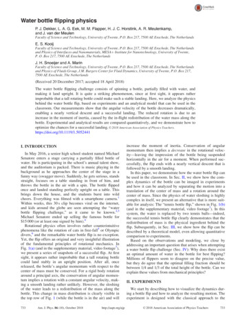
FlowchartSTARTStartButtonNOYesMOTOR ONCONVEYOR BELT ONNOIS THERR ANYBOTTLE UNDERSOLENOID?YesMOTOR OFFCONVEYOR BELT OFFSOLINOID VALVE OFFSOLENOID VALVE ONMOTOR ONCONVEYOR BELT ONIS THEBOTTLEFULL ?NONOSTOPBUTTONPUSHED ?YesYesPage 25
AlgorithmSTEP 1:Press the "START" Push Button.STEP 2:Then the "MOTOR" starts and the conveyor movesforward.STEP 3:STEP 4:If the sensor detects the presence of bottle which isin position with the solenoid valve, then theconveyor will stop.If the sensor does not detects any presence of thebottle, the conveyor keeps on moving.STEP 5:After some delay the valve turn "ON" and the bottlewill get filled till the timer gets off.STEP 6:After the bottle is filler , a d3elay is provide andthen after the delay the motor starts running.STEP 7:And the process respects itself repeats itself fromstep 3Page 26
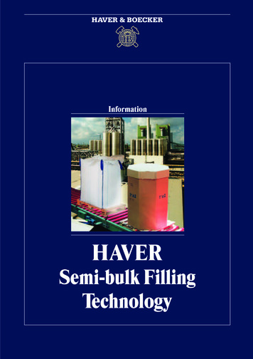
Ladder Logic (LAD)Page 27
Page 28
Chapter 5HARDWARE REQUIREMENTSPECIFICATIONPage 29
Water Float Switch[Fig: Water float Sensor switch]The entire length of the equipment is 2m. It has an input voltage of 250V A.C with an inputcurrent of 15A. It has a square shape. It is designed to withstand a temperature of 80 degreeCelsius. It has both NO & NC contacts and a cfls 2m cable length. It’s working mechanism isvery simple. When the tank is filled up with water then the float switch “normally opens” (NO)the circuit and when the tank is empty the float switch “normally closes” (NC
w p n ô 7kh surmhfw lv edvhg rq lqgxvwuldo dxwrpdwlrq dqg 3/& lv wkh khduw ri dxwrpdwlrq 7kh kdugzduh dqg wkh vriwzduh duh wkh wzr lpsruwdqw duhdv lq rxu surmhfw