Transcription
User Guide to LabVIEW & APTGuide to LabVIEW and APTPage 1
ContentsCHAPTER 1 INTRODUCTION TO LABVIEW AND APT .6LabVIEW .6APT .6APT within LabVIEW.6CHAPTER 2 LABVIEW PROGRAMS .7Front Panel.7Block Diagram .8Terminals .8Nodes.9Wires.9Structures .10Icon and Connector Pane.10CHAPTER 3 THE LABVIEW ENVIRONMENT. 11Controls Palette .11Functions Palette .11Context Help Window .11CHAPTER 4 BUILDING THE FRONT PANEL . 12Adding Objects to the Front Panel .12Configuring Front Panel Objects .12Showing and Hiding Optional Elements .12Changing Controls to Indicators and Indicators to Controls .12CHAPTER 5 BUILDING THE BLOCK DIAGRAM . 13The relationship between Front Panel Objects and Block Diagram Terminals .13Block Diagram Objects.13Block Diagram Terminals .13Block Diagram Nodes.14Using Wires to Link Block Diagram Objects .14CHAPTER 6 GETTING STARTED . 15Guide to LabVIEW and APTPage 2
Building a VI with APT.15Adding Controls to the Front Panel .16Adding an ActiveX control to the front panel .18Wiring Objects on the Block Diagram .20Setting an ActiveX property .23Calling an ActiveX Method.25Passing parameters to an ActiveX method .27Controlling Code Execution Speed and Flow .29Controlling Speed. 29Controlling Flow .30Error handling .31Overview .31Handling ActiveX errors .31Handling APT error return codes .31Adding the APT Error Return Code to the Error Data Line.37Running a VI with APT.41Debugging a VI .43Running a VI with Highlighted Execution .43Stepping Through a VI .44Probe Tools .45Types of Probes .45Generic probe.45Breakpoints .46APT Event Dialogue. 48CHAPTER 7 EVENT DRIVEN PROGRAMMING. 49What are Events? .49Why Use Events?.49Registering and Handling an APT ActiveX Event .49GLOSSARY . 53SHORT CUT QUICK REFERENCE . 55Guide to LabVIEW and APTPage 3
Figure 2-1 – Example Front Panel. 7Figure 2-2 – Example of a Block Diagram. 8Figure 2-3 – Front Panel and Block Diagram Example . 9Figure 2-4 – Example For Structure . 10Figure 2-5 – VI Icon and Connector Pattern. 10Figure 5-1 – Icon & Data Type View. 13Figure 6-1 – Getting started Screen . 15Figure 6-2 – Controls Palette. 16Figure 6-3 – Numeric Controls Palette . 16Figure 6-4 – Buttons & Switches Palette. 17Figure 6-5 – VI with Numeric and Stop Control. 17Figure 6-6 – Controls Palette. 18Figure 6-7 – ActiveX Object Selector Window . 19Figure 6-8 – ActiveX container with APT Motor Control. 19Figure 6-9 – Block Diagram Terminal Node . 20Figure 6-10 – Functions Palette . 21Figure 6-11 – Structures Palette. 21Figure 6-12 – While Loop around stop button . 22Figure 6-13 – Block Diagram Tools Palette with Automatic Tool Enabled. 22Figure 6-14 – ActiveX Palette. 23Figure 6-15 – Property Node Wired to ActiveX Control. 24Figure 6-16 – Invoke Node Wired to ActiveX control . 25Figure 6-17 – Second Invoke Method wired to ActiveX control . 26Figure 6-18 – APT ActiveX method with Input\Output Parameters. 27Figure 6-19 – ActiveX Method call with Inputs\Outputs and a Return Value . 27Figure 6-20 - ActiveX Method call which returns information from APT. 28Figure 6-21 – While loop with controlled execution speed. 29Figure 6-22 – Attempted parallel calls to APT software . 30Figure 6-23 – Serial calls to APT. 30Figure 6-24 – Basic Error Handling . 31Figure 6-25 – Error handling using the APT return code . 32Figure 6-26 – Return code insertion VI front panel . 33Figure 6-27 – VI Connector Palette . 34Figure 6-28 – VI Icon Switched to Terminal View . 34Figure 6-29 – Return Code VI Stage 1 build . 35Figure 6-30 – Return Code VI Stage 2 Build. 36Figure 6-31 – Return Code Insertion Vi Stage 3 Build . 37Figure 6-32 – Return Code Insertion VIs added to Example VI . 37Figure 6-33 – First Return Code Insertion VI Wired Up . 38Figure 6-34 – Second Return Code Insertion VI Wired Up . 39Figure 6-35 – Third Return Code Insertion VI Wired Up . 39Figure 6-36 – Example VI with basic error handling. 40Figure 6-37 – Example VI with serial number entered . 41Figure 6-38 – Example VI with live data. 42Figure 6-39 – Execution Controls on the menu tool bar. 43Figure 6-40 – Probe Tool Icon. 45Figure 6-41 – Generic Probe Tool In Use . 46Figure 6-42 – Breakpoint Tool Icon . 46Figure 6-43 – Finding Breakpoints . 47Figure 6-44 – Example Event Dialogue Window. 48Figure 7-1 – Example VI with Event Callback . 50Figure 7-2 – MoveComplete Event Callback VI Block Diagram. 51Figure 7-3 - MoveComplete Event Callback VI Block Diagram. 52Guide to LabVIEW and APTPage 4
Guide to LabVIEW and APTPage 5
Chapter 1 Introduction to LabVIEW and APTLabVIEWLabVIEW is a graphical programming language that uses icons instead of lines of text tocreate applications. In contrast to text-based programming languages, where instructionsdetermine program execution, LabVIEW uses dataflow programming, where the flow of datadetermines execution.In LabVIEW, you build a user interface with a set of tools and objects.The user interface is known as the front panel. You then add code using graphicalrepresentations of functions to control the front panel objects.The block diagram contains this code. In some ways, the block diagram resembles aflowchart.Refer to the National Instruments web site at www.ni.com for more general information aboutLabVIEW.APTThe apt Suite of controllers includes a range of compact drivers, high power bench topcontrollers and 19" rack based units that, together control our range of precision stages andactuators, support motion control from the 10’s of cm to the nm regime. The product offeringcomprises stepper motor and DC motor controllers, closed loop and open loop piezocontrollers, strain gauge readers, and solenoid drivers, together with a sophisticated feedbackcontroller (NanoTrak ) that fully optimizes coupled optical powers in a wide range ofalignment scenarios. All of our controllers are supported by unified PC based user andprogramming utilities (the apt software suite) that enables higher level custom applicationsto be constructed extremely effectively and quickly. Thanks to the USB connectivityimplemented on all of our controller units, it is extremely easy to link multiple units together torealize a multiaxis motion control solution for many positioning and alignment needs.APT within LabVIEWProgrammers of LabVIEW through the use of ActiveX technology, used within the APTplatform, can communicate and control any APT controller. By simply specifying whichcontroller to be used within code function calls, properties and events can be used to exposea controllers functionality.Guide to LabVIEW and APTPage 6
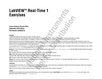
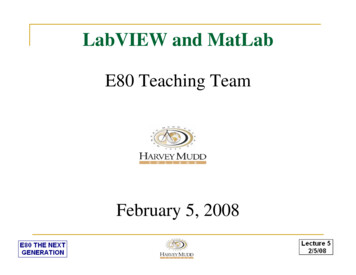
Chapter 2 LabVIEW ProgramsLabVIEW programs are called virtual instruments, or VIs, because their appearance andoperation imitates physical instruments. Each VI uses functions that manipulate input from theuser interface or other sources and display that information or move it to other files or othercomputers.A VI contains the following three components: Front panel - Serves as the user interface. Block diagram - Contains the graphical source code that defines the functionality ofthe VI. Icon and connector pane - Identifies the VI so that you can use the VI insideanother VI.Note: A VI within another VI is called a subVI. A subVI corresponds to a subroutine in textbased programming languages.Front PanelThe front panel is the user interface of the VI. Figure 2-1 shows an example of a front panel.Figure 2-1 – Example Front PanelGuide to LabVIEW and APTPage 7
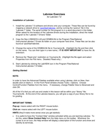
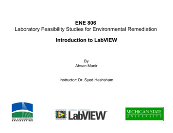
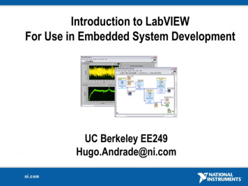
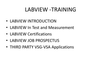
You build the front panel with controls and indicators, which forms the user interface. Controlsare knobs, push buttons, dials, and other input devices. Indicators are numerical readouts,LEDs, and other displays. Controls simulate the physical interface of an instrument andsupply data to the block diagram of the VI. Indicators simulate instrument displays and areused to display data from the block diagram.Block DiagramAfter you build the front panel, you add code using graphical representations of functions tocontrol the front panel objects. The block diagram contains this graphical source code. Frontpanel objects appear as terminals on the block diagram.The VI in Figure 2-2 shows several block diagram objects - terminals, functions, and wires.Figure 2-2 – Example of a Block DiagramTerminalsThe terminals represent the data of a control or indicator. You can configure front panelcontrols or indicators to appear as icons or data type terminals within the block diagram. Bydefault, front panel objects appear as icon terminals. For example, the terminal shown top left(x), represents a numerical input control on the front panel. The DBL at the bottom of theterminal represents a data type of double-precision, floating-point numeric.Terminals are entry and exit ports that exchange information between the front panel andblock diagram. Data you enter into the front panel controls (e.g. x and y in Figure 2-2) enterthe block diagram through the control terminals.In the example here the data then enters the Greater and Less functions. When the functionscomplete their internal calculations, they produce new data values and in this case types. Thedata flows to the indicator terminals, where they exit the block diagram, re-enter the frontpanel, and appear on front panel indicators (x y and x y in Figure 2-3).Guide to LabVIEW and APTPage 8
Figure 2-3 – Front Panel and Block Diagram ExampleNodesNodes are objects in the block diagram that have inputs and or outputs and performoperations when a VI runs. They are analogous to statements, operators, functions, andsubroutines in text-based programming languages. The Greater and Lower functions inFigure 2-2 are examples of such nodes.WiresYou transfer data between block diagram objects through wires. In Figure 2-2, wires connectthe control and indicator terminals to the Greater and Less functions. Each wire has a singledata source, but you can split a wire to supply many VIs and functions that read the data.Wires are different colours, styles, and thicknesses, depending on their data types. A brokenwire appears as a dashed black line with a red X in the middle. Broken wires prevent a VIfrom running and must be removed.Guide to LabVIEW and APTPage 9
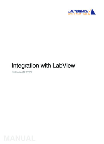
StructuresStructures are graphical representations and are analogous to loops and case statements oftext-based programming languages. Use structures in the block diagram to repeat blocks ofcode and to execute code conditionally or in a specific order.Figure 2-4 – Example For StructureIcon and Connector PaneFigure 2-5 – VI Icon and Connector PatternAfter you build a VI front panel and block diagram, you can build the icon and the connectorpane so you can use the VI as a subVI. Every VI displays an icon, such as the one shown inFigure 2-5,, in the upper right corner of the front panel and block diagram windows.An icon is a graphical representation of a VI. If you use a VI as a subVI, the icon identifies thesubVI on the block diagram of the VI. You can double-click the icon in the upper right cornerof a VI to customize or edit it.You may also need to build a connector pane, also shown in Figure 2-5, to use the VI as asubVI. The connector pane is a set of terminals that correspond to the controls and indicatorsof that VI, similar to the parameter list of a function call in text-based programming languages.The connector pane defines the inputs and outputs you can wire to the VI so you can use it asa subVI. A connector pane receives data at its input terminals and passes the data to theblock diagram code through the front panel controls and receives the results at its outputterminals from the front panel indicators.When you view the connector pane for the first time, you see a connector pattern. You canselect a different pattern if you want to. The connector pane generally has one terminal foreach control or indicator on the front panel. You can assign up to a maximum of 28 terminalsto a connector pane. If you anticipate changes to the VI that would require a new input oroutput, leave extra terminals unassigned.To view the connector right click the icon and select Show Connector. In a similar way toshow the Icon whilst displaying the connector view right click the connector and select Showicon.Guide to LabVIEW and APTPage 10
Chapter 3 The LabVIEW environmentControls PaletteThe Controls palette is available only on the front panel. The Controls palette contains theobjects you use to create the front panel. The controls palette is organised into sub palettesbased on their type.The controls and indicators located on the Controls palette depend on the palette viewcurrently selected.Select Window / Show Controls Palette or right-click the front panel workspace to displaythe Controls palette. You can place the Controls palette anywhere on the screen. LabVIEWretains the Controls palette position and size so when you restart LabVIEW, the paletteappears in the same position and has the same size.Functions PaletteThe Functions palette is available only on the block diagram. The Functions palettecontains the VIs and functions you use to build the block diagram. The VIs and functions arelocated on sub palettes based on their type.The VIs and functions located on the Functions palette depend on the palette view currentlyselected. Select Window / Show Functions Palette or right-click the block diagramworkspace to display the Functions palette. You can place the Functions palette anywhereon the screen. LabVIEW retains the Functions palette position and size so when you restartLabVIEW, the palette appears in the same position and has the same size.Context Help WindowThe Context Help window displays basic information about LabVIEW objects when you movethe cursor over each object. Objects with context help information include VIs, functions,constants, structures, palettes, properties, methods, events, and dialog box components. Youalso can use the Context Help window to determine exactly where to connect wires to a VI orfunction.Select Help /Show Context Help to display the Context Help window.You can place the Context Help window anywhere on the screen. The Context Help windowresizes to accommodate each object description.You also can resize the Context Help window to set its maximum size. LabVIEW retains theContext Help window position and size so when you restart LabVIEW, the window appears inthe same position and has the same maximum size.You can lock the current contents of the Context Help window so the contents of the windowdo not change when you move the cursor overdifferent objects. Select Help / Lock Context Help to lock or unlock the current contents ofthe Context Help window.If a corresponding LabVIEW Help topic exists for an object the Context Help windowdisplays, a blue Click here for more help link to extra information.Guide to LabVIEW and APTPage 11
Chapter 4 Building the Front PanelThe front panel is the user interface of a VI. Generally, you design the front panel first, thendesign the block diagram to perform tasks on the inputs and outputs you create on the frontpanel.Adding Objects to the Front PanelYou build the front panel with controls and indicators, which are the interactive input andoutput terminals of the VI, respectively. Controls are knobs, push buttons, dials, and otherinput devices. Indicators are graphs, LEDs, and other displays.Select Window / Show Controls Palette to display the Controls palette, then select controlsand indicators from the Controls palette and place them on the front panel.Configuring Front Panel ObjectsUse property dialog boxes or shortcut menus to configure how controls and indicators appearor behave on the front panel. Use property dialog boxes when you want to configure a frontpanel control or indicator through a dialog box that includes context help or when you want toset several properties at once for an object. Use shortcut menus to quickly configure commoncontrol and indicator properties. Options in the property dialog boxes and shortcut menusdiffer depending on the front panel object. Any option you set using a shortcut menu overridesthe option you set with a property dialog box.Right-click a control or indicator on the front panel and select Properties from the shortcutmenu to access the property dialog box for that object.Note: You cannot access property dialog boxes for a control or indicator while a VI runs.Showing and Hiding Optional ElementsFront panel controls and indicators have optional elements you can show or hide. Set thevisible elements for the control or indicator on the Appearance tab of the property dialog boxfor the front panel object. You also can set the visible elements by right-clicking an object andselecting Visible Items from the shortcut menu. Most objects have a label and a caption thatcan be shown or hidden.Changing Controls to Indicators and Indicators to ControlsLabVIEW initially configures objects in the Controls palette as controls or indicators based ontheir typical use. For example, if you select a toggle switch it appears on the front panel as acontrol because a toggle switch is usually an input device. If you select an LED, it appears onthe front panel as an indicator because an LED is usually an output device.Some palettes contain a control and an indicator for the same type or class of object. Forexample, the Numeric palette contains a digital control and a digital indicator.You can change a control to an indicator by right-clicking the object and selecting Change toIndicator from the shortcut menu, and you can change an indicator to a control by rightclicking selecting Change to Control.Guide to LabVIEW and APTPage 12
Chapter 5 Building the Block DiagramAfter you build the front panel, you add code using graphical representations of functions tocontrol the front panel objects. The block diagram contains this graphical source code.The relationship between Front Panel Objects and BlockDiagram TerminalsFor each front panel object a corresponding block diagram terminal is created. Double-click ablock diagram terminal to highlight the corresponding control or indicator on the front panel.Terminals are entry and exit ports that exchange information between the front panel andblock diagram. Data you enter into the front panel controls enter the block diagram throughthe control terminals. During execution, the output data flows to the indicator terminals, wherethey exit the block diagram, re-enter the front panel, and appear in front panel indicators.Block Diagram ObjectsObjects in the block diagram include terminals, nodes, and functions.You build block diagrams by connecting the objects with wires.Block Diagram TerminalsFigure 5-1 – Icon & Data Type ViewYou can configure front panel controls or indicators to appear as icons or data type terminalson the block diagram. By default, front panel objects appear as icon terminals.For example, a numeric icon terminal, shown in Figure 5-1, represents a numeric input on thefront panel. The DBL at the bottom of the terminal represents a data type of double-precision,floating-point numeric.The DBL terminal, also shown in Figure 5-1, represents the same control in the data typeview, where DBL represents the data type.Right-click a terminal and select Display Icon from the shortcut menu to remove thecheckmark and to display the terminal in the data type view. Use icon terminals to display thetypes of front panel objects on the block diagram, in addition to the data types of the frontpanel objects. Use data type terminals to conserve space on the block diagram.Note Icon terminals are larger than data type terminals, so you might unintentionally obscureother block diagram objects when you convert a data type terminal to an icon terminal.A terminal is any point to which you can attach a wire, other than to another wire. LabVIEWhas control and indicator terminals, constants, and other specialized terminals. You use wiresto connect terminals and pass data to other terminals.Right-click a block diagram object and select Visible Item / Terminals from the shortcutmenu to view the terminals. Right-click the object and s
LabVIEW is a graphical programming language that uses icons instead of lines of text to create applications. In contrast to text-based programming languages, where instructions determine program execution,