Transcription
How to Read a Schematic a learn.sparkfun.comtutorialAvailable online at: http://sfe.io/t91ContentsOverviewSchematic Symbols (Part 1)Schematic Symbols (Part 2)Name Designators and ValuesReading SchematicsResources and Going FurtherOverviewSchematics are our map to designing, building, and troubleshooting circuits. Understanding how toread and follow schematics is an important skill for any electronics engineer.This tutorial should turn you into a fully literate schematic reader! We'll go over all of thefundamental schematic symbols:Page 1 of 18
Then we'll talk about how those symbols are connected on schematics to create a model of acircuit. We'll also go over a few tips and tricks to watch out for.Suggested ReadingSchematic comprehension is a pretty basic electronics skill, but there are a few things you shouldknow before you read this tutorial. Check out these tutorials, if they sound like gaps in your growingbrain:What is Electricity?What is a Circuit?Voltage, Current, Resistance, and Ohm's LawSchematic Symbols (Part 1)Are you ready for a barrage of circuit components? Here are some of the standardized, basicPage 2 of 18
schematic symbols for various components.ResistorsThe most fundamental of circuit components and symbols! Resistors on a schematic are usuallyrepresented by a few zig-zag lines, with two terminals extending outward. Schematics usinginternational symbols may instead use a featureless rectangle, instead of the squiggles.Potentiometers and Variable ResistorsVariable resistors and potentiometers each augment the standard resistor symbol with an arrow.The variable resistor remains a two-terminal device, so the arrow is just laid diagonally across themiddle. A potentiometer is a three-terminal device, so the arrow becomes the third terminal (thewiper).CapacitorsThere are two commonly used capacitor symbols. One symbol represents a polarized (usuallyelectrolytic or tantalum) capacitor, and the other is for non-polarized caps. In each case there aretwo terminals, running perpendicularly into plates.The symbol with one curved plate indicates that the capacitor is polarized. The curved plate usuallyPage 3 of 18
represents the cathode of the capacitor, which should be at a lower voltage than the positive,anode pin. A plus sign should also be added to the positive pin of the polarized capacitor symbol.InductorsInductors are usually represented by either a series of curved bumps, or loopy coils. Internationalsymbols may just define an inductor as a filled-in rectangle.SwitchesSwitches exist in many different forms. The most basic switch, a single-pole/single-throw (SPST), istwo terminals with a half-connected line representing the actuator (the part that connects theterminals together).Switches with more than one throw, like the SPDT and SP3T below, add more landing spots for thethe actuator.Switches with multiple poles, usually have multiple, alike switches with a dotted line intersecting themiddle actuator.Page 4 of 18
Power SourcesJust as there are many options out there forpowering your project, there are a wide variety ofpower source circuit symbols to help specify the power source.DC or AC Voltage SourcesMost of the time when working with electronics, you'll be using constant voltage sources. We canuse either of these two symbols to define whether the source is supplying direct current (DC) oralternating current (AC):BatteriesBatteries, whether they're those cylindrical, alkaline AA's or rechargeable lithium-polymers, usuallylook like a pair of disproportionate, parallel lines:Page 5 of 18
More pairs of lines usually indicates more series cells in the battery. Also, the longer line is usuallyused to represent the positive terminal, while the shorter line connects to the negative terminal.Voltage NodesSometimes -- on really busy schematics especially -- you can assign special symbols to nodevoltages. You can connect devices to these one-terminal symbols, and it'll be tied directly to 5V,3.3V, VCC, or GND (ground). Positive voltage nodes are usually indicated by an arrow pointing up,while ground nodes usually involve one to three flat lines (or sometimes a down-pointing arrow ortriangle).Schematic Symbols (Part 2)DiodesBasic diodes are usually represented with a triangle pressed up against a line. Diodes are alsopolarized, so each of the two terminals require distinguishing identifiers. The positive, anode is theterminal running into the flat edge of the triangle. The negative, cathode extends out of the line inthe symbol (think of it as a - sign).There are a all sorts of different types of diodes, each of which has a special riff on the standarddiode symbol. Light-emitting diodes (LEDs) augment the diode symbol with a couple linesPage 6 of 18
pointing away. Photodiodes, which generate energy from light (basically, tiny solar cells), flip thearrows around and point them toward the diode.Other special types of diodes, like Schottky's or zeners, have their own symbols, with slightvariations on the bar part of the symbol.TransistorsTransistors, whether they're BJTs or MOSFETs, can exist in two configurations: positively doped, ornegatively doped. So for each of these types of transistor, there are at least two ways to draw it.Bipolar Junction Transistors (BJTs)BJTs are three-terminal devices; they have a collector (C), emitter (E), and a base (B). There aretwo types of BJTs -- NPNs and PNPs -- and each has its own unique symbol.The collector (C) and emitter (E) pins are both in-line with each other, but the emitter should alwayshave an arrow on it. If the arrow is pointing inward, it's a PNP, and, if the arrow is pointing outward,it's an NPN. A mnemonic for remembering which is which is "NPN: not pointing in."Page 7 of 18
Metal Oxide Field-Effect Transistors (MOSFETs)Like BJTs, MOSFETs have three terminals, but this time they're named source (S), drain (D), andgate (G). And again, there are two different versions of the symbol, depending on whether you'vegot an n-channel or p-channel MOSFET. There are a number of commonly used symbols for eachof the MOSFET types:The arrow in the middle of the symbol (called the bulk) defines whether the MOSFET is n-channelor p-channel. If the arrow is pointing in means it's a n-channel MOSFET, and if it's pointing out it's ap-channel. Remember: "n is in" (kind of the opposite of the NPN mnemonic).Digital Logic GatesOur standard logic functions -- AND, OR, NOT, and XOR -- all have unique schematic symbols:Adding a bubble to the output negates the function, creating NANDs, NORs, and XNORs:They may have more than two inputs, but the shapes should remain the same (well, maybe a bitbigger), and there should still only be one output.Integrated CircuitsPage 8 of 18
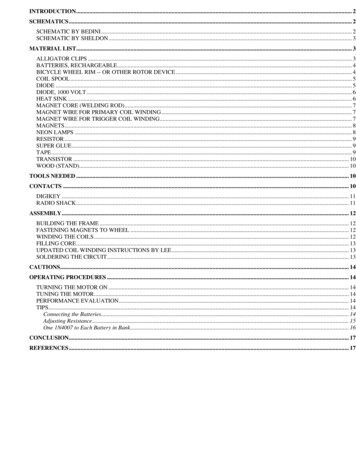
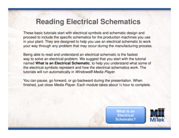
Integrated circuits accomplish such unique tasks, and are so numerous, that they don't really get aunique circuit symbol. Usually, an integrated circuit is represented by a rectangle, with pinsextending out of the sides. Each pin should be labeled with both a number, and a function.Schematic symbols for an ATmega328 microcontroller (commonly found on Arduinos), anATSHA204 encryption IC, and an ATtiny45 MCU. As you can see, these components greatly varyin size and pin-counts.Because ICs have such a generic circuit symbol, the names, values and labels become veryimportant. Each IC should have a value precisely identifying the name of the chip.Unique ICs: Op Amps, Voltage RegulatorsSome of the more common integrated circuits do get a unique circuit symbol. You'll usually seeoperation amplifiers laid out like below, with 5 total terminals: a non-inverting input ( ), invertinginput (-), output, and two power inputs.Page 9 of 18
Often, there will be two op amps built into one IC package requiring only one pin for power and onefor ground, which is why the one on the right only has three pins.Simple voltage regulators are usually three-terminal components with input, output and ground (oradjust) pins. These usually take the shape of a rectangle with pins on the left (input), right (output)and bottom (ground/adjust).MiscellanyCrystals and ResonatorsCrystals or resonators are usually a critical part of microcontroller circuits. They help provide a clocksignal. Crystal symbols usually have two terminals, while resonators, which add two capacitors tothe crystal, usually have three terminals.Headers and ConnectorsWhether it's for providing power, or sending out information, connectors are a requirement on mostcircuits. These symbols vary depending on what the connector looks like, here's a sampling:Page 10 of 18
Motors, Transformers, Speakers, and RelaysWe'll lump these together, since they (mostly) all make use of coils in some way.Transformers(not the more-than-meets-the-eye kind) usually involve two coils, butted up against each other, witha couple lines separating them:Relays usually pair a coil with a switch:Speakers and buzzers usually take a form similar to their real-life counterparts:And motors generally involve an encircled "M", sometimes with a bit more embellishment aroundthe terminals:Fuses and PTCsPage 11 of 18
Fuses and PTCs -- devices which are generally used to limit large inrushes of current -- each havetheir own unique symbol:The PTC symbol is actually the generic symbol for a thermistor, a temperature-dependent resistor(notice the international resistor symbol in there?).No doubt, there are many circuit symbols left off this list, but those above should have you 90%literate in schematic reading. In general, symbols should share a fair amount in common with thereal-life components they model. In addition to the symbol, each component on a schematic shouldhave a unique name and value, which further helps to identify it.Name Designators and ValuesOne of the biggest keys to being schematic-literate is being able to recognize which componentsare which. The component symbols tell half the story, but each symbol should be paired with both aname and value to complete it.Names and ValuesValues help define exactly what a component is. For schematic components like resistors,capacitors, and inductors the value tells us how many ohms, farads, or henries they have. For othercomponents, like integrated circuits, the value may just be the name of the chip. Crystals might listtheir oscillating frequency as their value. Basically, the value of a schematic component calls out itsmost important characteristic.Component names are usually a combination of one or two letters and a number. The letter part ofthe name identifies the type of component -- R's for resistors, C's for capacitors, U's for integratedcircuits, etc. Each component name on a schematic should be unique; if you have multiple resistorsin a circuit, for example, they should be named R1, R2, R3, etc. Component names help usreference specific points in schematics.The prefixes of names are pretty well standardized. For some components, like resistors, the prefixis just the first letter of the component. Other name prefixes are not so literal; inductors, forexample, are L's (because current has already taken I [but it starts with a C.electronics is a sillyplace]). Here's a quick table of common components and their name prefixes:NameIdentifierComponentRResistorsPage 12 of 18
Integrated CircuitsYCrystals and OscillatorsAlthough theses are the "standardized" names for component symbols, they're not universallyfollowed. You might see integrated circuits prefixed with IC instead of U, for example, or crystalslabeled as XTAL's instead of Y's. Use your best judgment in diagnosing which part is which. Thesymbol should usually convey enough information.Reading SchematicsUnderstanding which components are which on a schematic is more than half the battle towardscomprehending it. Now all that remains is identifying how all of the symbols are connected together.Nets, Nodes and LabelsSchematic nets tell you how components are wired together in a circuit. Nets are represented aslines between component terminals. Sometimes (but not always) they're a unique color, like thegreen lines in this schematic:Page 13 of 18
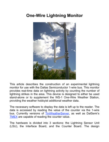
Junctions and NodesWires can connect two terminals together, or they can connect dozens. When a wire splits into twodirections, it creates a junction. We represent junctions on schematics with nodes, little dotsplaced at the intersection of the wires.Nodes give us a way to say that "wires crossing this junctionare connected". The absences of anode at a junction means two separate wires are just passing by, not forming any sort ofconnection. (When designing schematics, it's usually good practice to avoid these non-connectedoverlaps wherever possible, but sometimes it's unavoidable).Net NamesSometimes, to make schematics more legible, we'll give a net a name and label it, rather thanrouting a wire all over the schematic. Nets with the same name are assumed to be connected, eventhough there isn't a visible wire connecting them. Names can either be written directly on top of thenet, or they can be "tags", hanging off the wire.Page 14 of 18
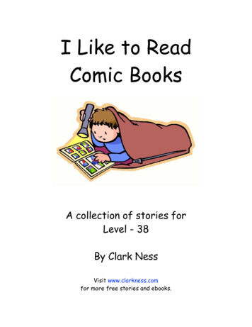
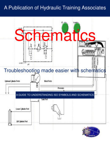
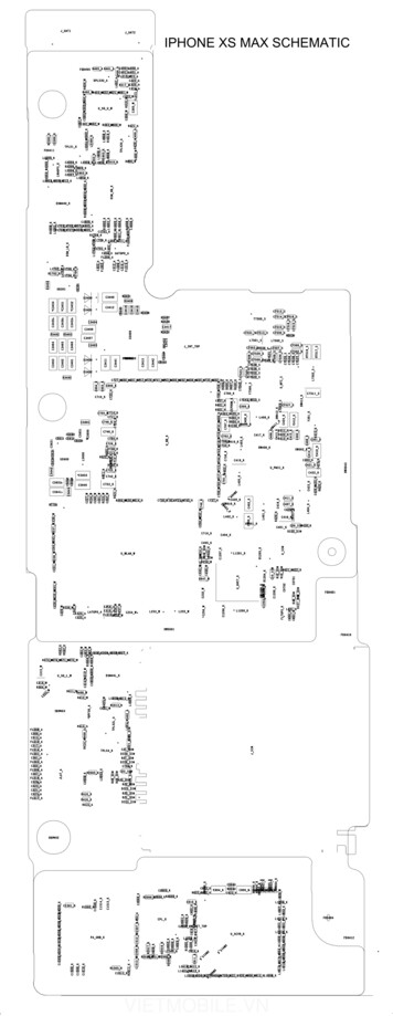
Each net with the same name is connected, as in thisschematic for an FT231X Breakout Board.Names and labels help keep schematics from getting too chaotic (imagine if all those nets wereactually connected with wires).Nets are usually given a name that specifically states the purpose of signals on that wire. Forexample, power nets might be labeled "VCC" or "5V", while serial communication nets might belabeled "RX" or "TX".Schematic Reading TipsIdentify BlocksTruly expansive schematics should be split into functional blocks. There might be a section forpower input and voltage regulation, or a microcontroller section, or a section devoted to connectors.Try recognizing which sections are which, and following the flow of circuit from input to output.Really good schematic designers might even lay the circuit out like a book, inputs on the left side,outputs on the right.Page 15 of 18
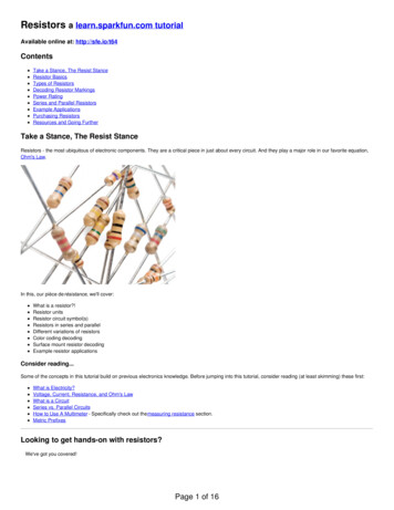
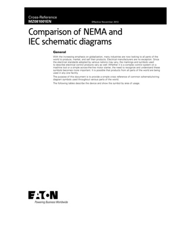
If the drawer of a schematic is really nice (like the engineer who designed thisschematic for theRedBoard), they may separate sections of a schematic into logical, labeled blocks.Recognize Voltage NodesVoltage nodes are single-terminal schematic components, which we can connect componentterminals to in order to assign them to a specific voltage level. These are a special application ofnet names, meaning all terminals connected to a like-named voltage node are connected together.Page 16 of 18
Like-named voltage nodes -- like GND, 5V, and 3.3V -- are all connected to their counterparts, evenif there aren't wires between them.The ground voltage node is especially useful, because so many components need a connection toground.Reference Component DatasheetsIf there's something on a schematic that just doesn't make sense, try finding a datasheet for themost important component. Usually the component doing the most work on a circuit is an integratedcircuit, like a microcontroller or sensor. These are usually the largest component, oft-located at thecenter of the schematic.Interested in learning more foundational topics?See our Engineering Essentials page for a full list of cornerstone topics surrounding electricalengineering.Take me there!Page 17 of 18
Resources and Going FurtherThat's all there is to schematic reading! Knowing component symbols, following nets, andidentifying common labels. Understanding how a schematic works opens up the whole world ofelectronics to you! Check out some of these tutorial, to practice your new-found schematicknowledge:Voltage Dividers - This is one of the most basic, fundamental circuits. Learn how to turn a bigvoltage into a smaller one, with just two resistors!How to Use a Breadboard - Now that you know how to read schematics, why not make one!Breadboards are a great way to make temporary, functional, prototype circuits.Working with Wire - Or, skip the breadboard and jump straight into wiring stuff up. Knowinghow to cut, strip, and connect wire is an important electronics skill.Series and Parallel Circuits - Building circuits in series or parallel requires a goodunderstanding of schematics.Sewing with Conductive Thread - If you don't want to work with wire, how about building an etextiles circuit with conductive thread? That's the beauty of schematics, the same schematiccircuit can be built in a number of different ways with a number of different mediums.learn.sparkfun.com CC BY-SA 3.0 SparkFun Electronics Niwot, ColoradoPage 18 of 18
Schematics are our map to designing, building, and troubleshooting circuits. Understanding how to read and follow schematics is an important skill for any electronics engineer. This tutorial should turn you into a fully literate schematic reader! We'll go over all of the fun